GENERAL DESCRIPTION
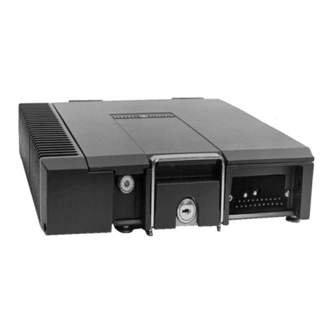
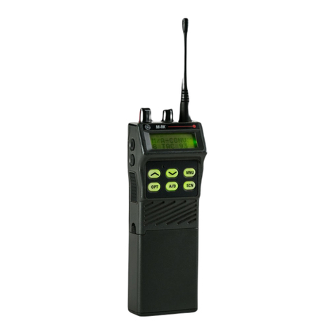
The Ericsson GE-MARC VE MDR Mobile Radio is a synthe-
sized, wideband radio that uses integrated circuits and microcom-
puter technology to provide high performance trunked and con-
ventional operation. The radio provides 10 Watts of RF power
output in the 806.0125-820.9875 MHz and 851.0125-865.9875
MHz bands. The receiver operates in the 851.0125-865.9875
MHz band.
All radio functions are stored in a programmableElectrically
Erasable PROM (EEPROM). The radio is field programmable
using an IBM compatible personal computer with the following
equipment:
•Serial Programming Interface Module TQ3310
•Programming Cable TQ3361
•MDR Programming Software TQ3355
With the interface equipment and software, the computer can
beusedtoprogram(orre-program)customer system frequencies,
Channel Guard tones and options. Selection of options is done
during radio initialization using the PC programmer.
The MDR Mobile Radio assembly consists of the following
circuit boards and assemblies:
•Duplexer Interface Board A4 19D903504
or
•Talk-Around Board A4
(optional) 19D903507
•RF Board A2 19D902123G18
•System Board A5 19D901891
•Logic Board A1 19D902172
•Audio Board A3 19D902188
•Handset Interface Board A9 19D903510
•Handset A8 344A3783P1
•Duplexer 19B801362P3
Thecircuitboardsareallmountedonamain casting toprovide
easy access for servicing. Interconnect plugs are used to connect
the boards to eliminate pinched wires and other wiring problems.
RF BOARD
The RF board includes the programmable frequency synthe-
sizer, transmitter exciter, receiver front end and IF circuitry.
Synthesizer Circuit
Thesynthesizergeneratesall transmit and receiveRFfrequen-
cies. The synthesizer frequency is controlled by the microproces-
sor located on the Logic Board.Frequency stability is maintained
bya temperaturecompensatedreferenceoscillatormodule. Trans-
mitaudiois processedonthe Audioand LogicBoards,andapplied
to the RF board to modulate the VCO and TCXO.
Transmitter Circuit
The transmitter consists of a fixed-tuned exciter module,a PA
module and a power control circuit. The PAmodule provides up
to a 20-Watt output to drive the duplexer. The power control
circuitcontrolsthePAmoduleby processingaDC feedbacksignal
from the duplexer interface board to maintain constant output
poweracrosstheband.TheRFoutputlevel isinternallyadjustable
for rated power. Thermistors in the control circuit protect the PA
from overheating by reducing the power output level.
Receiver Circuit
The dual conversion receiver circuit consists of a front end
section, 45 MHz first IF, a 455 kHz second IF, and FM detector.
All audio processing and squelch functions are accomplished on
the Audio Board.
DUPLEXER INTERFACE/
TALK-AROUND BOARD
Two versions of this board exist. The standard duplexer inter-
faceboard containsonlya directional coupler andtheTalk-around
board contains a directional coupler and RF switching circuitry
to provide talk around transmit capability. Radio Power distribu-
tion is also present on this board. The directional coupler samples
the duplexer output and provides a DCsignal proportional to the
detected power to the RF board power control circuitry.
AUDIO BOARD
The Audio Board provides analog to digital and digital to
analog conversion of the receive and transmit audio for digital
processing by the Logic Board. The board also contains analog
audio filtering, conventional analog tone processing, and the
receiver squelch.
LOGIC BOARD
The Logic Board controls the operation of the radio and
digitally processes the receive and transmit audio. The board
contains a microprocessor and associated memory circuits
which include an EPROM for controlling the processor and a
programmable "personality" memory (an Electrically Eras-
ablePROM-EEPROM) to store customer frequencies, tones,
and options. The microprocessor provides control data to the
Digital Signal Processor (DSP), conventional tone generation
anddetection, frequency data for the synthesizer,and sends and
receives data to/from the handsetfor the LCD displayand the
keypad commands.
SYSTEM BOARD
The system Board controls the main input power to the
radio. Thehandset POWERswitchand theIGNITION SENSE
input lead provide the necessary signals to the MOSFET
switching circuit. The board also interfaces all option connec-
tions from the internal boards in the radio with the optional
items outside of the radio. All external options for the radio,
interconnect to the System Board through the back of the radio
using an optional cable.
FRONT CAP ASSEMBLY
The front cap assembly contains the Handset interface
board. The Handset interface board provides compression of
the microphone audio from the handset. It also provides audio
compression for the received audio from the radio to handset
speakeraudioandexternalspeakeraudiopaths.A3-watt power
amplifier is provided on the Handset interface board to drive a
4-ohm external speaker. Separate mute control for the external
speaker and handset audio are also provided.
ACCESSORIES AND OPTIONS
PC PROGRAMMER OPTIONS
The radio is programmed using an IBM compatible per-
sonal computer equipped with a RS-232 port. Option TQ3310
provides the RS-232 serial interface unit and the cable between
the PC and the unit. An auxiliary power supply for the unit is
also included which is not needed to program the MDR.
Option TQ3361 provides the radio programming cable
between the PC interface unit and the radio microphone jack.
MDR PC programming software Option TQ3355 provides
both the 3.5 inch and 5.25-inch diskettes.
PC PROGRAMMED OPTIONS
Carrier Control Timer (CCT)
The Carrier Control Timer turns off the transmitter after the
microphone push-to-talk (PTT) switch has been keyed for a
pre-programmed time period. A pulsing alert tone will warn the
operator to unkey and then rekey the PTT to continue the
transmission. The timer can be programmed, using the PC
programmer, to time out for 30 seconds to 7.5 minutes in 30
second increments. The timer can be enabled or disabled for
each channel.
In Duplex mode a quick 2-note alert is heard at the interval
ofthecarrier timer tolet theuserknowthatintervalhaselapsed.
Channel Guard
Channel Guard provides a means of restricting calls to
specific radios through the use of a Continuous Tone Coded
Squelch System (CTCSS), or a Continuous Digital Coded
Squelch System (CDCSS). Channel Guard may be used only
in the conventional mode, not in the GE-MARC trunked mode.
Tone frequencies range from 67.0 Hz to 210.7 Hz in 0.1 Hz
steps. There are also 83 standard PC programmable digital
codes. The Channel Guard tone frequencies and codes are
software programmable. Tone frequenies and digital codes
cannot be mixed on the same RF frequency/channel. However,
multiple channels can be programmed with the same frequency
and different CG tones or DCG codes. These tone frequencies
and digital codes are listed in Table 1 - Channel Guard Tone
Frequencies and Table 2 - Digital Channel Guard Codes
(refer to the Table Of Contents).
Squelch Tail Elimination (STE)
STE is used with tone and digital Channel Guard to elimi-
nate squelch tails. The STE burst is transmitted when the
microphone PTT is released. The receiving radio decodes the
burst and mutes the receiver audio for 250ms. This mute time
allowsthe transmission to end and to mute thesquelchtail. The
radio looks for STE on the received signal when the handset is
either on or off-hook. The STE is enabled for transmit and/or
receive by PC programming the radio’s personality.
Hook Switch Programming Option
"OffHook Call"originateand"OnHookCall"terminate
can be enabledusing the PC programmer. When this option is
enabled placing the handset on the handset holder will termi-
nate a call. When originating a call, the number to be called can
be keyed in, or recalled from memory, and when the handset is
removed from the holder the call will be initiated without
LBI-38696 LBI-38696
3
