ERL aco COMO PRO User manual

www.electroreplacement.com
UK Sales & Technical Support
TEL: 01923 255 344
sales@electroreplacement.com
ACO Technical Support
www.support.aco.com.pl
www.aco.com.pl
UK Distributor of
ACO products
E&O.E.
COMO PRO Installation
and User Guide
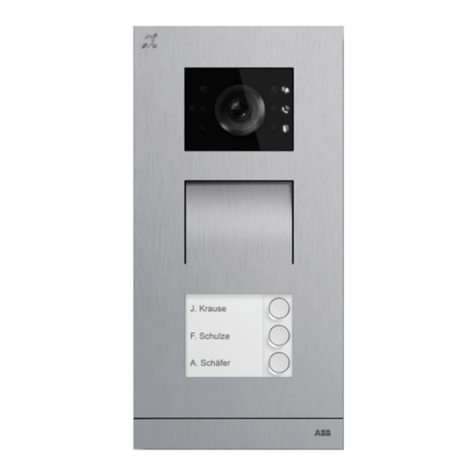
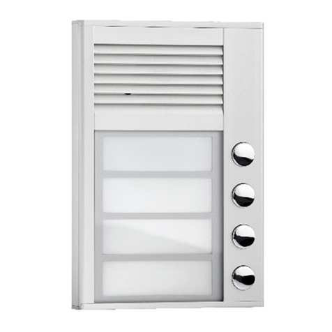
The COMO PRO video door entry system is designed
for single, multifamily and small commercial use.
Panels are available in Audio and Video, have a
2mm thick panel front in a brushed stainless-steel
finish, are vandal resistant and weatherproof. 1 to 6
independent call stations with built-in RFID proximity
card reader and includes a pre-programmed Master
Key Fob and User Key Fob.
The COMO PRO is easy to install and easy to use.
The heated camera enables the panel to operate
at low temperatures and prevents the lens from
fogging coupled with infra red LEDs a perfect picture
is guaranteed day and night no matter the weather
conditions.
Handset / Monitor Receivers:
• Compatible with PRO system receivers MPRO4, MPRO7,
GLASS-PRO-7 and UPRO (G3) all of which have 0 to 1023
address options
• Assign receivers to a call station via receiver dip switches
• Any number of receivers can be assigned to a single address
• Intercom facility available between video monitors on same
address
• Receivers with an assigned address 0 (broadcast) will be called
from any call button on the panel. By default the ringing time
is set to 45 secs. Call conversations can last 4 minutes
• Opening doors can be achieved using the key icon button on
receivers, a key fob at the panel or using an exit switch
Panel:
• System topology is based on CAT5 or higher with RJ 45 sockets
for easy installation
• Dedicated energy saving switch mode power supply with built
in 3 way video splitter for 3 monitors
• Integrated RFID reader (located over call station 1 name plate)
• Maximum of 10 proximity key fobs per call station
• High resolution colour camera (min. 600 lines) with a 2.8 mm
wide-angle lens
• ±20° adjustable camera in any direction
• Heated camera prevents lens from fogging
• Infrared night LED back lighting for perfect image day or night
• External camera can be connected to the audio panels
• 1 to 6 call buttons. 1 being the lowest, 6 the highest
• Keypad panels available
• Illuminated call buttons with backlit, easily interchangeable
description fields
• Illuminated keypad buttons (keypad version)
• Manage key fob access via Master Key Fob or via ACO PRO3
Manager software
• Control external devices such as a gate, barrier, blinds, or
lighting with PRO-I/O extension module
• Works with exit buttons and e-Locks
• Vandal resistant and weatherproof
• Panel generates a busy signal if no receiver is installed
Advanced settings easily configured
using the ACO PRO3 Manager software

www.electroreplacement.com
UK Sales & Technical Support
TEL: 01923 255 344
sales@electroreplacement.com
ACO Technical Support
www.support.aco.com.pl
www.aco.com.pl
UK Distributor of
ACO products
E&O.E.
PRO3 Manager PC Software
The PRO3 Manager PC software allows full control of the panel
and handset/monitors. The software is free to download and will
work on all windows 7, 8 , 10 laptop / PCs. Drivers may need to be
installed. Once connected you will be able to easily configure:
• Key fobs (adding and removing)
• Receiver addresses and description
• ELOCK OUTPUT settings: Electric Lock, Reverse, Relay
• Door activation/opening times from 0.6 to 25secs. Default time
is 4sec
• Door opening delay (from the moment the exit button is
pressed to the actual opening of the door from 1 s to 25s)
• Individual DEV ID numbers of each panel
• Compatible with earlier PRO systems
• Additional panels within one system, e.g. Master and
Secondary Panels. (Switching camera views the switch module
VIDEO-SW2 MINI 60 is required
• Individual handset/monitor volume and ring type
• Brightness and colour parameters
Additionally you can:
• Save and load configuration files
• Save to Drop Box and Google Drive
Cable Requirement
• Connecting the panel, power supply and receivers together
is recommended using CAT5e cable or higher into the RJ45
sockets to ensure optimal transmission, especially for video
image or distortion may occur
• If other types of cables are used tests should be completed to
ensure proper operation of the system
• RJ45 CAT5e is the easiest way to connect a panel but a
successful setup can also be achieved using the ARK screw
terminals and following the T568B standard diagram
• All cables must be clamped in line with the T568B standard
Cable Distances:
The maximum cable run length between:
• The panel and power supply is 100m
• The receivers inside unit and power supply is 70m
• Distances over 100m an additional power supply should be
used
It is possible to extend the distance by increasing the cross section
of wires, using thicker wires and an additional power supply. If
a distance other than those specified should be tested in a trial
situation and checks on the whole system should be carried out.
NOTE: Avoid routing cables (especially the signal ones for: Audio/
Video) in close proximity to the cables of other installations (power,
telecommunication, alarm systems) as this may adversely affect the
operation of the system.

www.electroreplacement.com
UK Sales & Technical Support
TEL: 01923 255 344
sales@electroreplacement.com
ACO Technical Support
www.support.aco.com.pl
www.aco.com.pl
UK Distributor of
ACO products
E&O.E.
Panel Installation
• The surface mounting cover protects the system from adverse
weather conditions especially water
• Setting the cameras height around 1.6m from the ground is
a good starting point, however in order to obtain the optimal
view experimenting with height and location is recommended
• Avoid locations where the camera lens is exposed to direct,
perpendicular, light rays from sunlight, street lights and other
light sources
• In order to get the best tightness it is recommended to cut out
only the holes that are necessary to mount the panel. There is
a thin foam gasket on the front surface of the flush mounted
box. Pay attention when screwing the panel front so that it
adheres to the gasket evenly and with its entire surface
Master and Secondary Panel Assembly
Connecting two panels is possible in a Master and Secondary setup
Jumper positions should be set on each panel main board:
• Master Panel: J1 Jumper = Open (Master)
• Secondary Panel: J1 Jumper = Closed (Secondary
In a Single panels installation the J1 Jumper should be set to Master:
• Secondary Audio panels can be connected directly to the +DC
Power and - DC Power GND and Line terminals
• Secondary video panels should be connected using the VIDEO-
SW2 MINI-60 camera switch
NOTES:
• The master panel always has priority of all functions, opening
doors, activate a call, standby mode
• The panel that initialises the call will automatically connect to
the caller. The receiver will only be able to unlock the door that
the calling panel operates
• If a second call is attempted from another panel while the first
panel is in use, the caller will hear an engaged tone
Panel Volume Settings
The panel default volume settings are set at the factory but can be
easily changed using the dials situated on the panel main board.
• MIC adjusts the sensitivity of the panel microphone
• SPK adjusts the panel volume
• BEEP adjusts the panel beeps
HOLE 1 Flush mounting box main wire feed
HOLE 2 Additional module slot - break offto use
HOLE 3
For mounting in a steel column or similar structure
Maximum wall thickness 32 mm - additional set of
gaskets and screws should be used
HOLE 4 Auxiliary holes are for temporary mounting, e.g.
using nails in a soft material such as Styrofoam
HOLE 5 Panel mounting holes for flush fitting. Appropriate
screws, wall plugs and gypsum should be used
HOLE 6
Surface box mounting holes. Screw housing bolts
evenly into the assembly box using a 3 mm Allen
key
HOLE 7 Surface mounting box cable entry slot

www.electroreplacement.com
UK Sales & Technical Support
TEL: 01923 255 344
sales@electroreplacement.com
ACO Technical Support
www.support.aco.com.pl
www.aco.com.pl
UK Distributor of
ACO products
E&O.E.
PROXIMITY CARD MANAGEMENT
• The first key fob programmed will become the Master Key Fob
(supplied and pre-programmed with kits)
• The Master Key Fob will then be used to program all
subsequent key fobs going forward
• To enter programming mode a Master Key Fob must be used
• Maximum of 10 key fobs per station
Where is the RFID Reader?
• The RFID Reader is situated directly behind Call Station 1 name
plate
Adding user key fobs
• Hold the Master Key Fob to the panel RFID Reader
• During the door opening process hold the next key fob to the
panel. (You will be automatically entered into Programming
Mode at this point)
• Hold new key fob to RFID Reader until an audible beep is heard
to confirm card acceptance
• Repeat holding key fobs to panel RFID
If an unregistered key fob is used at the panel a short triple beep sound
will be emitted
Exiting Programming Mode
• Programming Mode will time out after 5 seconds of no activity
Deleting key fobs from an allocated call station
• Hold Master Key Fob to Panel activating door unlocking process
• Immediately press and hold relevant call station for 4 seconds
• A loud beep will be emitted for about 10 - 15 seconds
• When it stops the call station has been cleared of all key fobs
including Master Key Fob
• This can be confirmed by holding Master Key Fob to the panel -
as now unregistered you will hear 3 short beeps
Deleting individual key fobs is only possible via the software
Creating a Master Key Fob
• Panel must be off
• Press and hold the first call button
• Turn power on > a loud continuous beep will sound
• Take your finger offthe call button
• Hold and place an unregistered key fob to the RFID Reader
• You will hear the beep stop for a split second then a second
short beep will sound
• The Master Key Fob is now programmed
Supply voltage 15VDC ± 5%
Power consumption in standby mode ~ 2.5W
Maximum power consumption 400mA
Electric strike supply voltage 12VDC - 15VDC
Permissible electric strike output load 1.5A
Output type Normal or reversing (default:
normal)
Lock activity time 0.6 to 25s (default: 4s)
Output control type Pulse to the electric strike (default)
or constant to the relay
Camera angle About 75º
Camera adjustment angle Vertical and horizontal 20º
Connector type RJ45 socket / removable ARK
screw connectors
Panel front material Stainless steel
External input impedance for opening
(INPUT)
≤20Ω, input type: normally open
(NO)
INPUT activation delay time 0 - 25s (default: 0s)
Panel front dimensions 286 x 90 mm (height x width)
Proximity RFID Standard Unique 125KHzs
maximum number of supported
proximity cards 70
10 for premises + 10
administrative ones
COMO PRO Technical Specification
Contact
your local
wholesaler
for sales
enquires!
Popular Intercom System manuals by other brands
Fanvil
Fanvil i20S user manual
SkyBell
SkyBell WiFi Video Doorbell Installation & starting guide
Linear
Linear ACCESS AE-100 Guide Installation and programming instructions
Harding
Harding MicroComm DXL IMS-640 operating instructions
sks
sks HT 4600 operating instructions
Aiphone
Aiphone KC-32EU Operation manual

