Erma Electronic SSI 9001 User manual
ERMA
Electronic GmbH
ERMA
Electronic GmbH
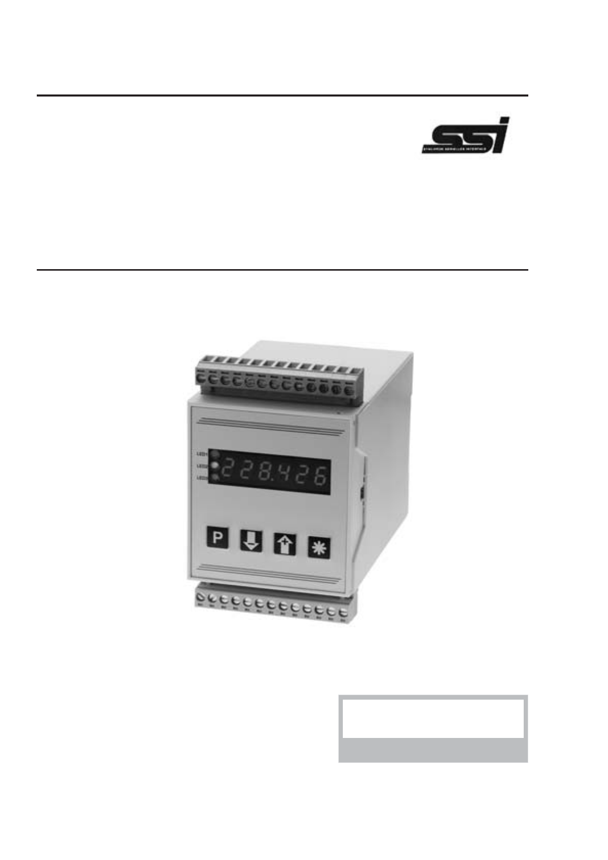
SSI 9001
Digital Converter
For Absolute Encoders With Synchron-Serial-Interface
Instruction Manual

Trademarks
All trademarks they are named ore portrayed in the text are registered trademarks of its
owner. The trademarks are recognized by ERMA-Electronic.
Warranty
For delivered products our "Allgemeine Lieferungs- und Zahlungsbedingungen" are effective.
In no event ERMA-Electronic or its suppliers shall be liable for any other damages whatsoever
(including, without limitation, damages for loss of business profits, business interruption or
other pecuniary loss) arising out of or inability to use this product.
All products from ERMA-Electronic are warranted against defective material and workmanship
for a period of two (2) years from date of delivery. If it is necessary to return the product to ERMA,
the sender is responsible for shipping charges, freight, insurance and proper packaging to pre-
vent breakage in transit. ERMA's warranty does not apply to defects resulting from action of the
buyer, such mishandling, improper interfacing, operation outside of design limits, improper repair
or unauthorized modification.

CONTENTS
1. Description ...........................4
2. Safety instructions .......................5
2.1. Symbol explanation ....................5
3. Mounting ............................6
3.1. Place of operation .....................6
3.2. Mounting of signal converter ................6
4. Electrical connections .....................7
4.1. General instructions ....................7
4.2. Hints against noisy environment ..............7
4.3. Connection and pin assignment ..............8
4.4. Connection of absolute encoder ..............9
4.5. Connection of digital user inputs ..............9
4.6. Connection of alarm outputs (relay) ............9
4.7. Connection of analog output ................10
4.8. Connection of RS 485 interface ..............10
4.9. Connection of power supply voltage ............10
4.9.1. Supply voltage 18 ... 36 V DC ...........10
5. Startup procedure .......................11
6. Pushbuttons- and LED-functions ...............12
6.1. Function of buttons and LEDs ...............12
7. Modes ..............................13
7.1. Operation level .......................13
7.2. Access-code level .....................14
7.3. Programming level .....................15
8. Procedure of programming ..................16
8.1. Changing or controlling parameters ............16
8.2. Overview of the programming levels ...........17
8.3. Programming level for configuration P-00 .........18
8.3.1. Scaling the display range .............20
8.4. Programming level of alarms P-02 ............21
ERMA-Electronic GmbH 2

8.4.1. Alarm output functions ...............22
8.4.2. Alarm high setpoint ................23
8.4.3. Alarm low setpoint .................23
8.5. Programming level for analog output P-03 ........24
8.5.1. Scaling of the analog output ............24
8.5.2. Analog output at failure Indication ........24
8.5.3. Analog output at overflow resp. underflow ....25
8.6. Programming level of serial interface P-04 ........26
8.6.1. Transmission-Mode ................26
8.7. Programming quick reference ...............27
9. Software functions .......................29
9.1. Master/Slave-Mode ....................29
9.2. Zero point adjustment ...................29
9.2.1. Zero point adjustment by pressing button .....29
9.2.2. Zero point adjustment by offset value .......30
9.3. Incremental measurement .................31
9.4. Direction of rotation ....................31
9.5. MIN/MAX value detection .................31
9.6. Hold function ........................32
9.7. Display test ........................32
9.8. Main reset .........................33
10. Error codes ...........................33
10.1. Encoder not connected “Err01" ..............33
10.2. Waiting for data input “Err02" ...............33
10.3. External clock frequency too high “ERR03" ........33
11. Technical Specifications ....................34
11.1. Electrical datas ......................34
11.2. Mechanical datas .....................35
11.3. Environmental conditions .................35
12. Ordering Information ......................36
13. Notices .............................37
Stand : 28.11.2000
SI9001CE.PUB
3 ERMA-Electronic GmbH

1. Description
The digital converter Model SSI 9001 is an instrument to convert datas of absolute
encoders with Synchronous-Serial-Interface (SSI) in an analog output signal.
Simultaneous, it can carried out an alarm point controlling.
Standard hardware
• isolated analog output 0 - 10 V, 2 - 10 V, 0 - 20 mA, 4 - 20 mA
• two relay alarm outputs
• two programmable digital input channels
• three programmable pushbuttons
Standard software
• Programming of encoder datas
• Scaling-factor
• Zero point adjustment
• Offset value
• Display segment test
• Hold function
• MAX/MIN value detection
• Auto-Reset of MAX/MIN value
• Edit of the alarm value during normal measurement
• Display of error messages
Following options are available
• RS485 interface
1. Description
ERMA-Electronic GmbH 4

2. Safety instructions
This instrument is produced in accordance with Class II of IEC 348 and VDE 0411.
When delivered the instrument has been tested to meet all functions described.
Before installing the instrument please read the mounting and servicing instructions.
We have no liability or responsibility to customer or any other person or entity with
respect to any liability, loss or damage caused or alleged to be caused directly or
indirectly by equipment or software sold or furnished by us. Read the installation
instruction carefully. No liability will be assumed for any damage caused by improper
installation.
Inspect the instrument module carton for obvious damage. Be shure there are no
shippingandhandingdamagesonthemodulebeforeprocessing.Donotapplypower
to the instrument if it has been damaged.
ERMA’s warranty does not apply to defects resulting from action of the buyer, such
as mishandling, improper interfacing, operation outside of design limits, improper
repair or unauthorized modifications.
2.1. Symbol explanation
Caution: Will be used at dangerous for life and health !
Attention: Will cause damage
Instruction: If not noticed, trouble may occur
Tip: Useful hints for better operation
Caution Attention Instruction Tip
2. Safety instructions
5 ERMA-Electronic GmbH
3. Mounting
3.1. Place of operation
Attention must be payed to the protection against humidity, dust and high tempera-
tures at the place of operation.
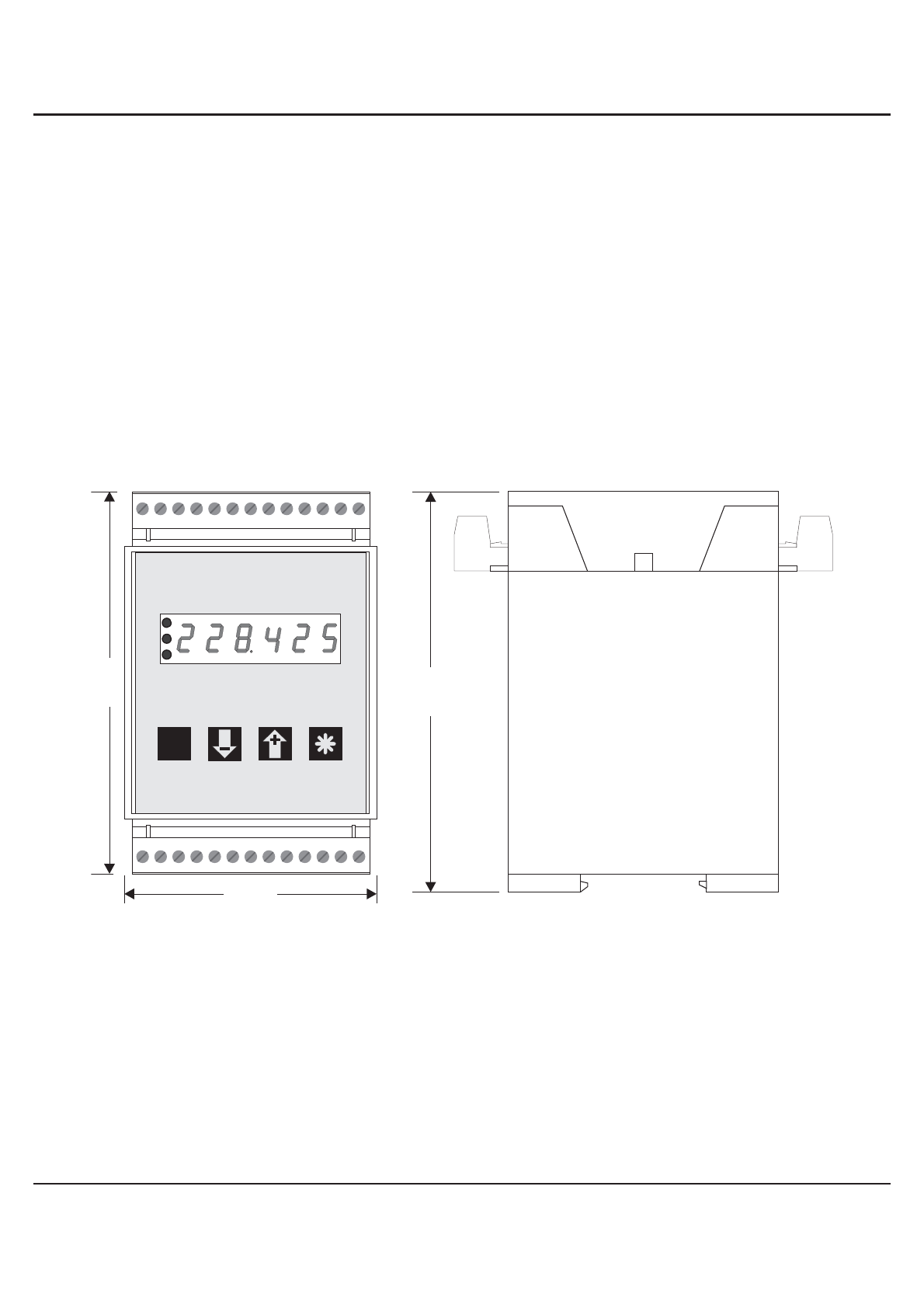
3.2. Mounting of signal converter
• through simple snap up at 35 mm rail (DIN EN 50022)
105
70
110
P
LED3
LED2
LED1
ERMA-METER
3. Mounting
ERMA-Electronic GmbH 6

4. Electrical connections
4.1. General instructions
• It is forbidden to plug or unplug connectors with voltage applied
• Attach input and output wires to the connectors only without voltages
applied
• Cords must be provided with sleeves
• Attention must be paid that the power supply voltage applied will
agree with voltage noticed at the name plate.
• The instrument has no power-on switch, so it will be in operation as
soon as the power is connected.
4.2. Hints against noisy environment
All inputs and outputs are protected against noisy environment and high voltage
spikes. Nevertheless the location should be selected to ensure that no capacitive or
inductive interference can have an effect on the instrument or the connection lines.
It is advisable:
• To use shielded cables.
• The wiring of shields and ground (0V) should be star-shaped.
• The distance to interference sources should be as long as possible.
If necessary, protective screen or metal enclosures must be provi-
ded.
• Coils of relays must be supplied with filters.
• ParallelwiringofinputsignalsandACpowerlinesshouldbeavoided.
4. Electrical connections
7 ERMA-Electronic GmbH
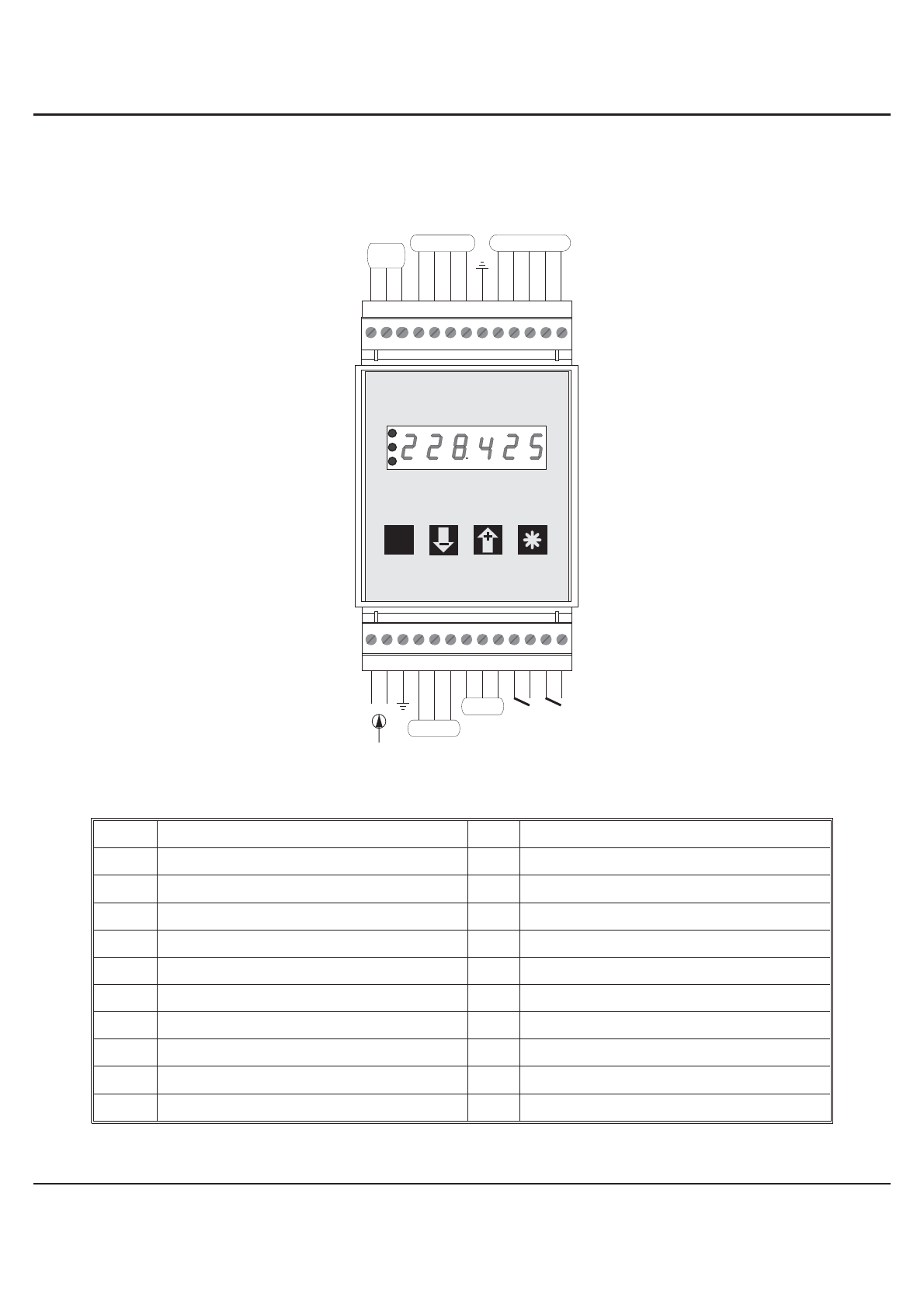
4.3. Connection and pin assignment
All inputs and outputs are connectors, designed as plug-in screw terminals.
Pin assignment:
1 Power supply DC (+) 14 SSI-Signalinput, Clock (+)
2 Power supply DC (-)
15 SSI-Signalinput, Clock (-)
3 Ground connection
16
SSI-Signalinput, Data (+)
4
Analog output 0/2-10 V (+)
17 SSI-Signalinput, Data (-)
5 Analog output 0/4-20 mA (+)
18 SSI-Signalinput, GND (0 V)
6 Analog output, GND (-)
19 Ground connection
7 Option RS485, A (+)
20 -
n.c.
8 Option RS485, B (-) 23 n.c.
9 Option RS485, GND 24 Digital user input 1
10/11
Alarm (relay) output 1 25 Digital user input 2
12/13
Alarm (relay) output 2 26 Digital GND
P
LED3
LED2
LED1
ERMA-METER
1 2 5 7 8 9643 11 12
10 13
14
1526 25 24 23 22 21 20 19 18 17 16
analog output
alarm 1 alarm 2
+-
signal input
digital
inputs
RS 485
n.c.
4. Electrical connections
ERMA-Electronic GmbH 8
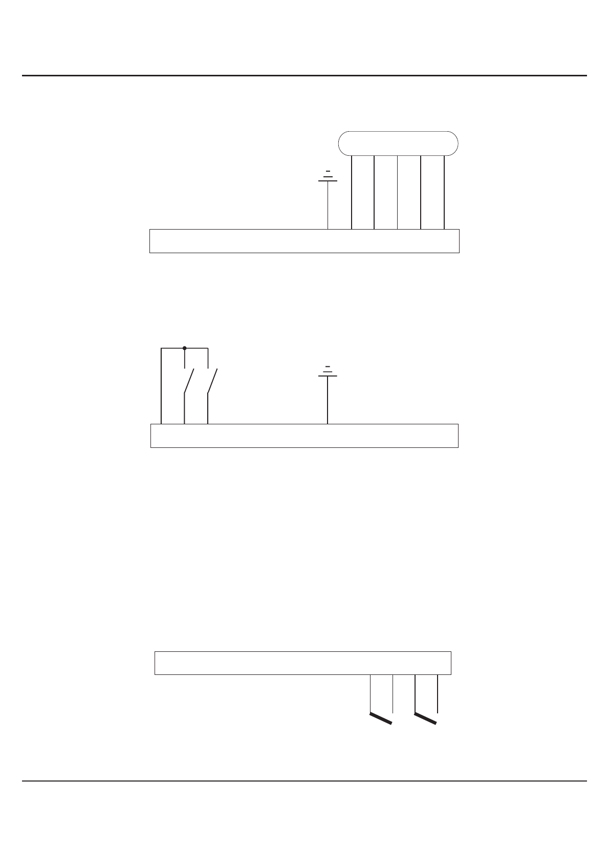
4.4. Connection of absolute encoder
4.5. Connection of digital user inputs
Digital input 1
• active => Connecting Screw Terminal 24 to 26
• Connecting to Ground, low active
Digital input 2
• active => Connecting Screw Terminal 25 to 26
• Connecting to Ground, low-active
4.6. Connection of alarm outputs (relay)
14
1526 25 24 23 22 21 20 19 18 17 16
Encoder
Clock -
Clock +
Data+
Data-
(GND)
14
1526 25 24 23 22 21 20 19 18 17 16
1 2 5 7 8 9643 11 12
10 13
alarm 1 alarm 2
4. Electrical connections
9 ERMA-Electronic GmbH

4.7. Connection of analog output
4.8. Connection of RS 485 interface
4.9. Connection of power supply voltage
4.9.1. Supply voltage 18 ... 36 V DC
1 2 5 7 8 9643 11 12
10 13
A-
AU+
AI+
1 2 5 7 8 9643 11 12
10 13
+-
A(+)
GND
B(-)
89
7
6
5
4
3
2
1
A
B
A
B
4. Electrical connections
ERMA-Electronic GmbH 10

5. Startup procedure
Attention must be paid that thepower supply voltage appliedwillagree with
the voltage noticed at the name plate. Switch the power supply on (supply
voltageappliedtoscrewterminal1and2).Afterabout2secondsthedisplay
will indicate the applied input signal.
When delivered, the instrument is programmed with a standard configura-
tion (default values). By programming the customer can change the stand-
ard configuration according to his measuring task.
Attention ! When the instrument is built in a machine and the customer
wants to change the configuration, attention must be paid, that no damage
will occur to the machine!
5. Startup procedure
11 ERMA-Electronic GmbH
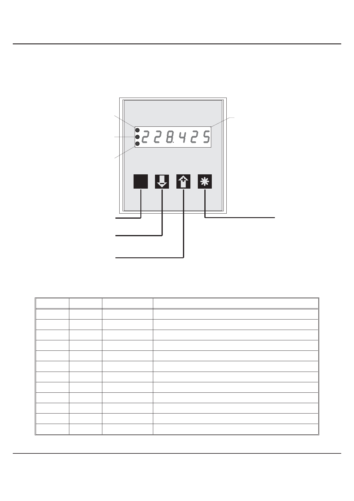
6. Pushbuttons- and LED-functions
There are four push buttons in the front. These push buttons can have different
functions. The functions of the push buttons can be used for programming and for
service.
6.1. Function of buttons and LEDs
LED 1 LED 2 LED 3 Description
x x off encoder- or hold value is displayed
x x red MIN value is displayed
x x green MAX value is displayed
x x green/flashs programming mode is activated
x off x alarm 2 is not activated
x lights x alarm 2 is activated
x flashs off alarm point 2 is displayed
x flashs green/flashs alarm point 2 is changed
off x x alarm 1 is not activated
lights x x alarm 1 is activated
flashs x off alarm point 1 is displayed
flashs x green/flashs alarm point 1 is changed
x = state of the LED is not considered
P
LED3
LED2
LED1
ERMA-METER
6 decades display
LED2
LED1
LED3
programming button function button
button "-" / alarm 1 / alarm 2
direct input-, max- ,min-
or hold value
button "+" / alarm 1 / alarm 2
direct input-, max- ,min-
or hold value
6. Pushbuttons- and LED-functions
ERMA-Electronic GmbH 12
7. Modes
Theoperationandtheprogrammingof thepanelmeterisorganizedinseveralstates:
• Operation level
• Access-code level
• Programm level
7.1. Operation level
In the state “operation level” the normal functions of the instrument are activated. A
normal measurement cycle looks like below:
• Read the value of encoder, calculate and display
• Evaluate the digital inputs
• Alarm outputs
• Analog output
Dependent on the programming of the parameter 0-14 (function of key ), 0-15
(function of key ) and 0-13 (function of key ), following key-functions are
available in the operation level.
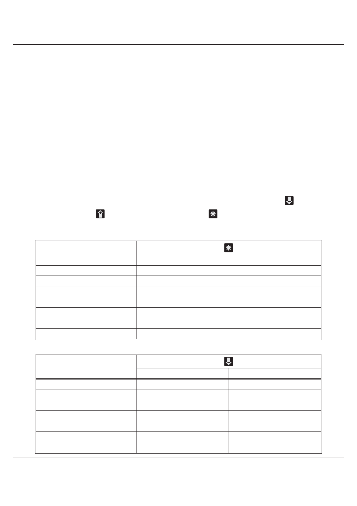
Parameter 0-13
Function of pushbutton “*” By pressing
0 No function
1 Reset the MIN/MAX value
2 Taring
3 Clear tara value
4 Incremental measurement
5 Manual reset of alarms
6 start single serial transmission
Parameter 0-14
Function of pushbutton “-” By pressing Pressing during 3 sec.
0 No function -
1 Display value of encoder -
2 Display MAX value -
3 Display MIN value -
4 Display hold value -
5 Display alarm point 1 Change alarm point 1
6 Display alarm point 2 Change alarm point 2
7. Modes
13 ERMA-Electronic GmbH
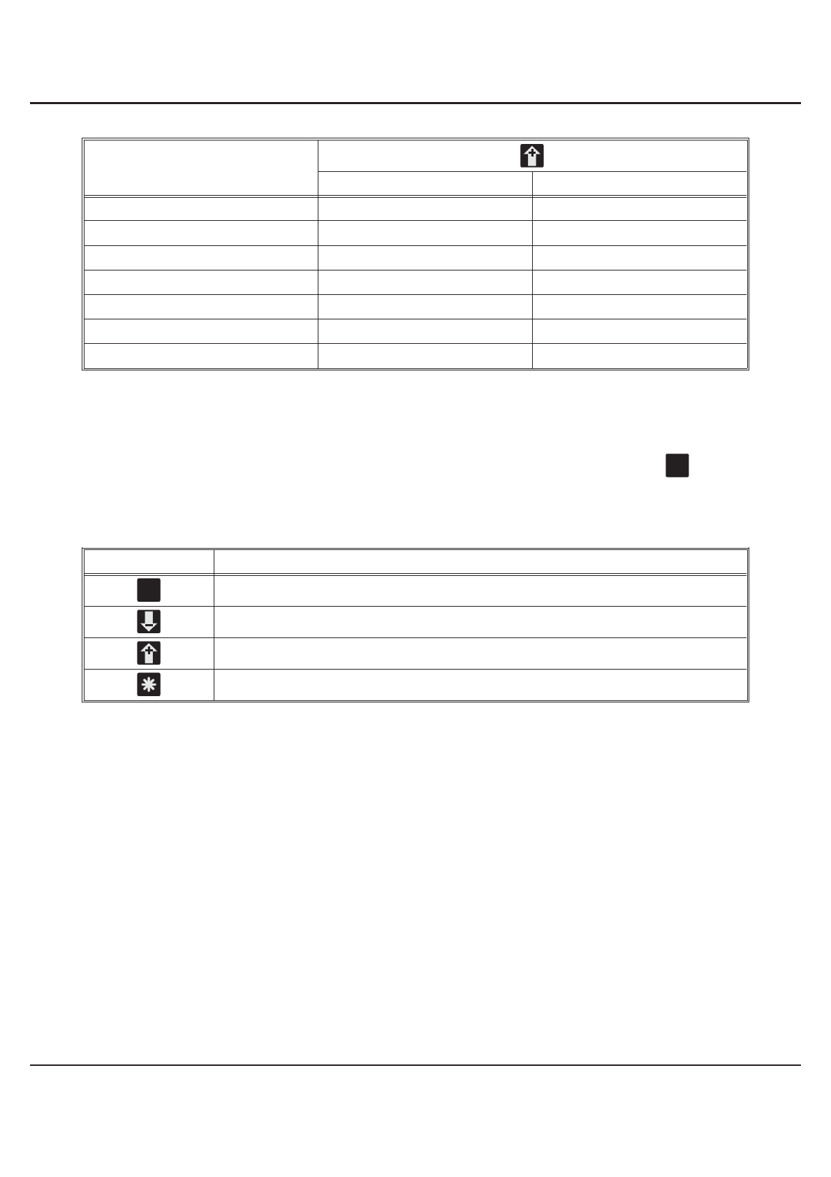
Parameter 0-15
Function of pushbutton “+” By pressing Pressing during 3 sec.
0 No function -
1 Display value of encoder -
2 Display MAX value -
3 Display MIN value -
4 Display hold value -
5 Display alarm point 1 Change alarm point 1
6 Display alarm point 2 Change alarm point 2
7.2. Access-code level
Thestate“access-codelevel”becomesactivebypressingthepushbutton during
the state “operation level”. The display shows “c000". During the state ”access-code
level" the normal functions of the instrument are active.
pushbutton Function
Confirm of the displayed access-code
Increase the access-code
Decrease the access-code
Programmed function
P
P
7. Modes
ERMA-Electronic GmbH 14
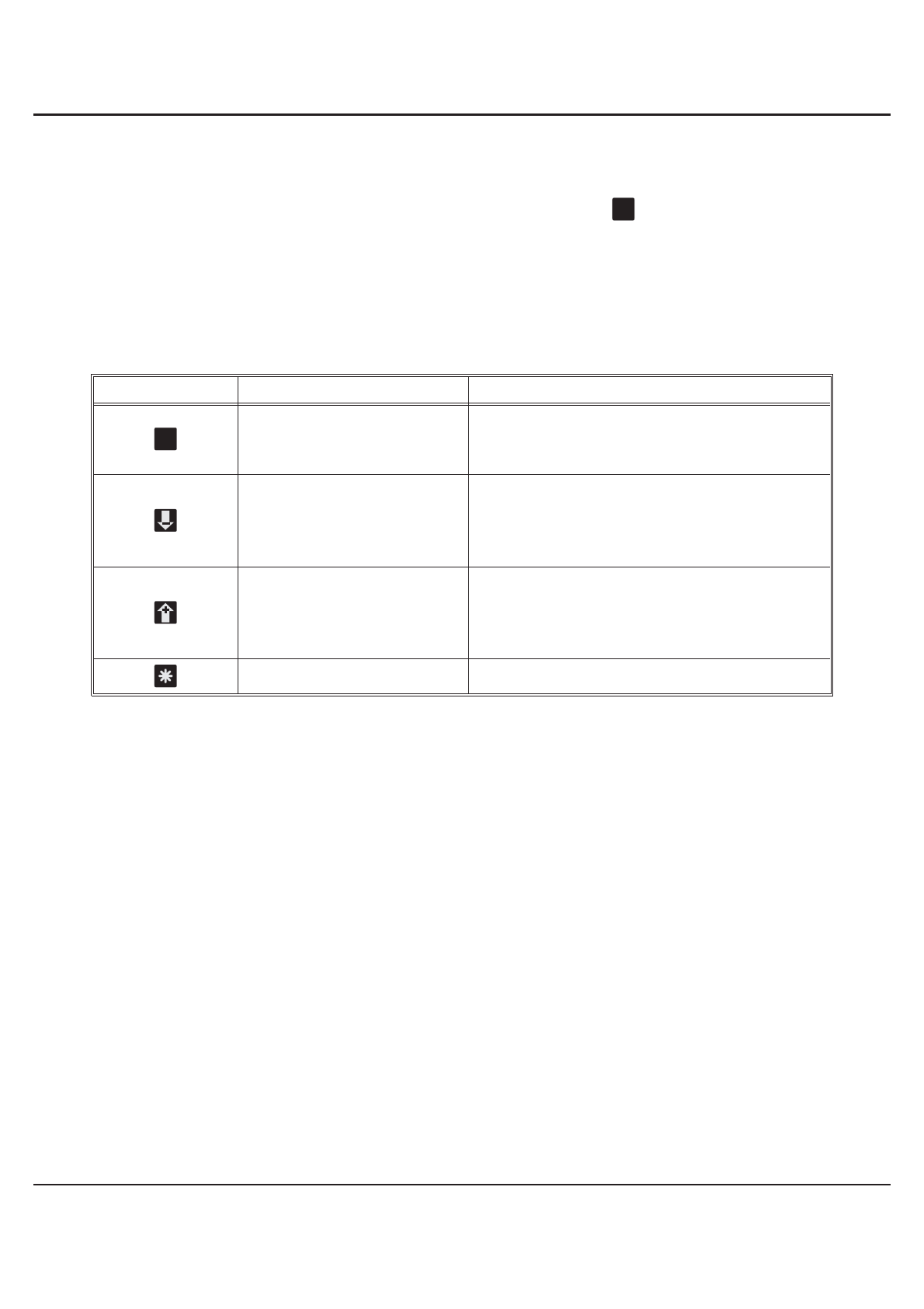
7.3. Programming level
The state “programm level” becomes active by entering the right access-code. The
access-code must be confirm by pressing the pushbutton . The programming is
organized in following steps:
• Selection of a programming level
• Selection of a parameter
• Change of the selected parameter
Pushbutton Press Pressing during 3 sec.
Selection of
- Programming level
- Parameter -
Decrease of
- Programming level
- Number of parameter
- Value of parameter
-
Increase of
- Programming level
- Number of parameter
- Value of parameter
-
- Break the programming routine
P
P
7. Modes
15 ERMA-Electronic GmbH

8. Procedure of programming
The procedure of programming is organized in several different steps.
Access to the selection of the programming levels
• Pressing pushbutton => access-code enter is active
• The display shows “c000"
• Changing the access-code by pressing the pushbutton or and confirm
the changed access-code by pressing the pushbutton
If the entered access-code is not correct, the instrument will jump back to the state
“operation level”.
8.1. Changing or controlling parameters
Activating the programming routine
• Pressing pushbutton
• LED 3 flashs green
• The display shows “c000"
• Changing the access-code by pressing the pushbutton or
• Confirm access-code by pressing the pushbutton
• The display shows “P-00"
Leaving the programming routine
• Pressing the pushbutton or until the display shows “PEnd”
• Confirm the display “PEnd” by pressing the pushbutton
• LED 3 is off
• The active state of the panel meter is “operation level”
Selection of the programming level
• Selecting the programming level by pressing the pushbutton or
• Confirm the programming level by pressing the pushbutton
• Thedisplayshowsthenumberofthe parameterof theselectedprogramminglevel
For example: “0-00" => parameter 0 of the programming level 0
For example: ”2-00" => parameter 0 of the programming level 2
P
P
P
P
P
P
8. Procedure of programming
ERMA-Electronic GmbH 16

Leaving the programming level
• Pressing the pushbutton or until the display shows “xEnd”
For example: “0End” => leaving programming level 0
For example: “2End” => leaving programming level 2
• Confirm the display “xEnd” by pressing the pushbutton
• The display shows the programming level
For example: “P-00" => for programming level 0
For example: ”P-02" => for programming level 2
Selection of the parameter
• Selection the parameter by pressing the pushbutton or
• Confirm the parameter by pressing the pushbutton
• The display shows the last programmed value of the selected parameter
Change and controll the selected parameter
• Change the value of the parameter by pressing the pushbutton or
• Confirm the value of the parameter by pressing the pushbutton
• The display shows the programming level and the number of the parameter
For example: “0-05" => parameter number 5 of programming level 0
For example: ”2-08" => parameter number 8 of programming level 2
8.2. Overview of the programming levels
The parameters of the panel meter are organized in different programming levels.
P-00: Programming level for configuration of the panel meter
The configuration is used to adapt the absolute encoder and the panel meter.
P-02: Programming level for the alarms
This programming level is used to programm all settings for the alarm outputs.
P-03: Programming level for the analog output
This programming level is used to programm all settings of the analog output.
P-04: Programming level of the serial interface
This programming level is used to programm the address and baud rate of the serial
interface.
P
P
P
8. Procedure of programming
17 ERMA-Electronic GmbH

8.3. Programming level for configuration P-00
Param. Description Setting range Default
value
0-00 Resolution (Bits) 10 .. 25 12
0-01 Output code
0 -> Gray
1 -> Binary 0..1 0
0-02 Master/Slave-Mode
0 -> Instrument = Master
1 -> Instrument = Slave 0..1 0
0-03 Clock for Master-Mode
0 -> Frequency = 200 kHz
1 -> Frequency = 100 kHz 0..1 0
0-04 Zero adjustment
0 -> Zero adjustment without sign
1 -> Zero adjustment with ± display 0..1 0
0-05 Counting direction
0 -> increasing clockwise rotation
1 -> increasing anticlockwise rotation 0..1 0
0-06 Scalingfactor 0.00001 .. 9.99999 1.00000
0-07 Offset value -99999 .. 999999 0
0-08
Programmable decimal points
0 -> XXXXXX
1 -> XXXXX.X
2 -> XXXX.XX
3 -> XXX.XXX
4 -> XX.XXXX
5 -> X.XXXXX
0..5 0
0-09
Data source of the display
0 -> Encoder value
1 -> MAX value
2 -> MIN value
3 -> Hold value
0..3 0
0-10 Reset time of the MIN/MAX value
0 -> No automatically reset
X -> Reset time in seconds 0..100 0
0-11
Function of digital user input 1
0 -> No function
1 -> Reset MIN/MAX value
2 -> Taring of encoder
3 -> Clear tara value of encoder
4 -> Incremental measurement
0..11 0
8. Procedure of programming
ERMA-Electronic GmbH 18

0-11
continue of 0-11:
Function of digital input 1
5 -> Manual reset of alarms
6 -> Hold function
7 -> Display test
8 -> Display value of encoder
9 -> Display MAX value
10 -> Display MIN value
11 -> start single serial transmission
0..11 0
0-12
Function of digital user input 2
0 -> No function
1 -> Reset MIN/MAX value
2 -> Taring of encoder
3 -> Clear tara value of encoder
4 -> Incremental measurement
5 -> Manual reset of alarms
6 -> Hold function
7 -> Display test
8 -> Display value of encoder
9 -> Display MAX value
10 -> Display MIN value
11 -> start single serial transmission
0..11 0
0-13
Function of push button “*”
0 -> No function
1 -> Reset MIN/MAX value
2 -> Taring of encoder
3 -> Clear tara value of encoder
4 -> Incremental measurement
5 -> Manual reset of alarm
6 -> start single serial transmission
0..6 0
0-14
Function of pushbutton “-”
0 -> No function
1 -> Display value of encoder
2 -> Display MAX value
3 -> Display MIN value
4 -> Display hold value
5 -> Display/change alarm point 1
6 -> Display/change alarm point 2
0..6 0
8. Procedure of programming
19 ERMA-Electronic GmbH
Table of contents
Other Erma Electronic Media Converter manuals


Popular Media Converter manuals by other brands

Keysight Technologies
Keysight Technologies M9188A Startup guide

Calibre
Calibre HQView-300 Series operating instructions

Gefen
Gefen ex•tend•it VGA to DVI Conversion Box user manual

Ross
Ross DAC-8013A user manual

IMC Networks
IMC Networks McPc-Gigabit supplementary guide

GÜDE
GÜDE PRO DHH 1100/15 TEZ operating instructions


