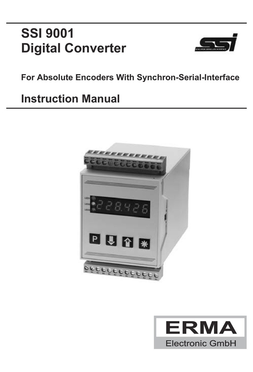
Erma Electronic AF 9001 User manual

AF 9001
Analogue To Freqency Converter
Instruction Manual

Warranty
For delivered products our "Allgemeine Lieferungs- und Zahlungsbedingungen" are effective. In no event
we or our suppliers shall be liable for any other damages whatsoever (including, without limitation, dama-
ges for loss of business profits, business interruption or other pecuniary loss) arising out of or inability to
use this product.
All our products are warranted against defective material and workmanship for a period of two (2) years
from date of delivery. If it is necessary to return the product, the sender is responsible for shipping charges,
freight, insurance and proper packaging to prevent breakage in transit. The warranty does not apply to de-
fects resulting from action of the buyer, such as mishandling, improper interfacing, operation outside of de-
sign limits, improper repair or unauthorized modification.
Trademarks
All trademarks that are named or portrayed in the text are registered trademarks of its owner. The tra-
demarks are recognized by ERMA-Electronic.

Inhaltsverzeichnis
1. Description ...........................4
2. Safety Instructions .......................5
2.1. Symbol explanation ....................5
3. Mounting ............................6
3.1. Place of operation .....................6
3.2. Mounting of signal converter................6
4. Electrical connections .....................7
4.1. General instructions ....................7
4.2. Hints against noisy environment..............7
5. Function .............................8
6. Opening the case ........................8
7. Jumper and DIP-Switch ....................9
8. Connections ..........................11
8.1. Srew Terminals Assignment................11
8.2. Connections of the input channels ............11
8.3. Connections of the output channel ............12
8.4. Connection of the power supply used ...........12
9. Startup Procedure .......................13
10. Handling of Malfunction ....................13
11. Technical Datas.........................14
11.1. Elektrical Datas ......................14
11.2. Environmental Conditions .................14
11.3. Mechanical Datas .....................15
12. Ordering information ......................15
ERMA-Electronic GmbH 3
State : 11.2012
af9001_man_en.vp
Technical subjects to change

1. Description
The unit AF 9001 is an analogue to frequency converter for converting an analogue
input signal into a proportional output frequency signal.
The input signal (either voltage or current) is processed by an internal converter into a
frequency.
The input signal may be a voltage 0...10V or a current 0/4...20 mA. The final value of
the input signal (20 mA resp. 10 V) results in an internal frequency of 25 kHz. The ac-
tual frequency at the output channel is determined by an internal divider value. The
value of the divider can be adjusted by the user. The range of the divider value can be
selected between 1 and 4080. The value can be adjusted by the user. For this reason
the converter is provided with an internal 8-pole DIP-Switch (divider range 1...255)
and 5 jumper. positions (ranges 1, 2, 4, 8, 16). The output frequency is proportional to
the input frequency dividesd by the value of the divider. The puls/pause ratio is 1:1.
Constrution
Picture 1, the block diagramm shows the construction and the functions of the srew
terminals.
4ERMA-Electronic GmbH
1. Description
Input Channel
1
2
3
4
5
6
7
9
Analogue to
Frequecy Converter
Frequency
Divider
Output Channel
Optocoupler
Power Supply
0...10V(-)
common plus (+)
Power supply (+)
Power supply (GND)
Protective ground
Collector (+)
Emitter (-)
0/4...20mA(-)
Figure 1

2. Safety Instructions
This instrument is produced in accordance with Class II of IEC 348 and VDE 0411.
When delivered the intrument has been tested to meet all functions described. Before
installing the instrument please read the mounting and servicing instructions. We
have no liability or responsibility to customer or any other person or entity with respect
to any liablity, loss or damage caused or alleged to be caused directly or indirectly by
equipment or software sold or furnished by us. Read the installation instruction care-
fully. No liability will be assumed for any damage caused by improper installation.
Inspect the instrument module carton for obvious damage. Be shure there are no
shipping and handling damages on the module before processing. Do not apply po-
wer to the instrument if it has damaged.
ERMA’s warranty does not apply to defects resulting from action of buyer, such as
mishandling, improper interfacing, operation outside of design limits, improper repair
or unauthorized modifications.
2.1. Symbol explanation
Caution: Will be used at dangerous for life and health !.
Attention: Will cause damage
Instruction: If not noticed, trouble may occur
Tip: Useful hints for better operation
ERMA-Electronic GmbH 5
2. Safety Instructions
Caution Attention Instruction Tip

3. Mounting
3.1. Place of operation
Attention must be paid to the protection against humidity, dust and high temperatures
at the place of operation.
3.2. Mounting of signal converter
Simple snap up at 35 mm rail (DIN EN 50022).
6ERMA-Electronic GmbH
3. Mounting
99 17,5
114,5

4. Electrical connections
4.1. General instructions
•It is forbidden to plug or unplug terminals with voltage applied.
•Attach input and output wires to terminals only without voltages ap-
plied.
•Cords must be provided with sleeves.
•Attention must be paid that the power supply voltage applied will
agree with the voltage noticed at the name plate.
•The instrument has no power-on switch. So it will be in operation as
soon as the power supply voltage is connected.
4.2. Hints against noisy environment
All inputs and outputs are protected against noisy environment and high voltage spi-
kes. Nevertheless the location should be selected to ensure that no capacitive or in-
ductive interference can have an effect on the instrument or connection lines.
It is advisable:
•To use shielded cables.
•The wiring of shields and groung (0V) should be star-shaped.
•The distance to interference sources should be as far as possible. If
necessary, protective screen or metal enclosures must be provi-
ded.
•Coils of relays must be supplied with filters.
•Parallel wiring of input output lines to any AC power lines should be
avoided.
•The lines should be as short as possible.
•It is advisable to use shielded twisted pair cable for input and output
lines.
ERMA-Electronic GmbH 7
4. Electrical connections

5. Function
The unit AF 9001 is an analogue to frequency converter for converting an analog in-
put signal into a proportional output frequency. The input signal (either voltage or cur-
rent) is processed by a converter into a frequency. The final value of the input signal
(20 mA resp. 10 V) results in a internal frequency of 25 kHz. The actual frequency at
the output channel can be adjusted by a built in divider. The wished dividing value
may be adjusted by the user. This could be done by an internal 8-pole DIP-switch and
5 jumper. The output frequency is proportional to the input frequency and the
puls/pause ratio is 1:1.
The input channel is protected against overvoltages and spikes. The following inputs
ranges are deliverable. The desired input range has to be specified according to the
ordering information.
•0...10 V
•0...20 mA
•4...20 mA
The output channel is isolated. The output transistor is able to switch up to 30 V and
25 mA.
The frequency at the final value of the input signal is an internal freqency of 25 kHz .
By the built -in divider the freqency can be adjusted in a wide range to customer requi-
rements.
6. Opening the case
Many functions of the model AF 9001 can be configurated according the reqirements
of the user. For this reason there are some jumper and one DIP-switche located insi-
de of the unit. For the configuration of the of AF 9001 the device must be opened.
For opening the case only a small screw driver is needed. With the screw driver the
two flat links between the top and the base of the housing have to be pressed inwardly
on both sides. When the flat links
were pressed, the top can be sepa-
rated from the base. Now, the PCB
can be pulled out together with the
top of the housing.
Look for the possible jumper and
DIP-switch settings in figure 4 at the
next page.
To put the housing together, just
push the top with the PCB inside the
base until the flat links snap in on
both sides.
8ERMA-Electronic GmbH
5. Function
Figure 2

7. Jumper and DIP-Switch
The printed board is shown in figure 4. In figure 4 the equipment for configurations is
labelled. The equipment consists of an array of jumpers labelled J3 and one 8-pole
DIP-Switch.
Ajusting the divider:
For adjusting the value of the divider the 8-pole DIP-switch table 1, and the jumper
field J3 must be used.
•8-pole DIP-Switch::Select of a numerical value of table 1 from 1 to 255
•Jumper field J3:: Select four values from 1 to the value of 16
Selection of a numerical value:
There is one 8-pole DIP-switch located at the PCB.board. The adjustment of the swit-
ches must be made using binary code. The possible values to be selected are shown
in table.
Example:
If wanted a desired divider value is
value = 100.
The following switches must in po-
sition "ON"
Number 7, value = 64
Number 6, value = 32
Number 3, value = 4
ERMA-Electronic GmbH 9
7. Jumper and DIP-Switch
Figure 3
Number of DIP-Sitch Divider Value
11
22
34
48
516
632
764
8128

The finaly divider value is the sum of the switches located in position ON.
sum = 64 + 32 + 4 = 100
For the adjustment of the jumper field J3 there is only one jumper which must be
used. The values selectable are 1, 2, 4, 8, or 16. The value of the 8-pole DIP-Switch
will be multiplied with th value selected by the position of the jumper of field J3.
Example:
The desired divder value will be 800. In this case the jumper of field "8" must be selec-
ted. The value consists as follow:
Divider value = 100 * 8 = 800
10 ERMA-Electronic GmbH
7. Jumper and DIP-Switch
Figure 4
1
ON 8-poliger DIP-S.
2 3 4 5 6 7 8
1 2 4 8 16
J3

Hints for adjusting and operating of the output channel
Some hints when using the output channel must be observed. The output channel is
realized by an optocoupler device. So the external voltage at the output channel and
the load resistance applied must meet the requirements of the unit.
The load resistance applied is dependent of the adjusted frequency of the output
channel. The table below shows the value of the required load resistance using diffre-
rent output frequencies.
Max. output frequency Value of load resistance
25 kHz 1 k
20 kHz 1k
15 kHz 1.5k
10 kHz 3k
5 kHz 6k
1 kHz >6k
8. Connections
8.1. Srew Terminals Assignment
10...10 V input voltage terminal (-) 7Collector of the output optocoupler (+)
20/4...20 mA input current terminal (-) 8nc
3Common plus for Input channel 1/2 (+) 9Emitter of the output optocoupler (-)
4Power Supply DC (+) 10 nc
5Power Supply (GND) 11 nc
6Protective ground 12 nc
8.2. Connections of the input channels
ERMA-Electronic GmbH 11
8. Connections
Input (+)
Input (-)
Voltage input
0...10V
Input (+)
Input (-)
Current input
0/4...20mA

8.3. Connections of the output channel
8.4. Connection of the power supply used
12 ERMA-Electronic GmbH
8. Connections
4
5
Power supply (GND)
Protective ground
Power supply (+)
6
7
9
Emitter
Collector
AF 9001
+3...30 VDC

9. Startup Procedure
All devices of ERMA-Electronic GmbH are tested for perfect function du-
ring production as well as when delivered. Nevertheless it is possible that
a device won’t work. That is not allways a reason by the new device. The-
re are many small reasons that will result in misfunctions. If the AF 9001
won’t work properly, please check the following points.
•Look for proper supply voltage
•Look for proper wiring of supply
•Look for proper configuration of the divider value
•Look if high voltage spikes are existing and have an influence to the de-
vice.
If all tests are all right, the device must be send back for controling.
10. Handling of Malfunction
All devices of ERMA-Electronic GmbH are tested for perfect function during producti-
on as well as when delivered. Nevertheless it is possible that a device won’t work.
That is not allways a reason by the new device. There are many small reasons that
will result in misfunctions. If the AF 9001 won’t work properly, please check the follo-
wing points.
•Look for proper supply voltage
•Look for proper wiring of supply
•Look for proper configuration of the divider value
•Look if high voltage spikes are existing and have an influence to the device.
If all tests are all right, the device must be send back for controling.
Attention! If changing the jumper or DIP-switch configuration, power supply must be
switched off and on.
Delivery status:
Input voltage level = 24 V;
Multiplier = 10,0
Measuring time = 1 period
ERMA-Electronic GmbH 13
9. Startup Procedure

11. Technical Datas
11.1. Elektrical Datas
Input channels
Input voltage range : 0...10 V, adjustable
Input resistance : 100 k
Input current ranges : 0/4...20 mA
IInput resistance : 100
Divider : 100
Range : 1...4080
Output channels
Low-side or high-side switching : adjustable
Isolation voltage : 500 V
Voltage, opto-coupler : max. 30 V DC
Current, opto-coupler : max. 25 mA
Frequency, opto-coupler : max. 25 kHz
Accuracy : better 0,2%
Power supply
Standard : 18...36 V DC
Current consumption : max. 56 mA (24 V DC)
Isolation voltage : 500 V
Other supply voltages : see ordering information
11.2. Environmental Conditions
Operating temperature : 0 .. 50 °C
Storage temperature : -20 .. 70 °C
Humidity : < 80 %, not condensing
Protection : class II
Protection index : case IP 40
: connections IP 20
Field of application : class 2
: overvoltage protection II
CE : in conform with 89/336/EWG
: NSR 73/23/EWG
14 ERMA-Electronic GmbH
11. Technical Datas

11.3. Mechanical Datas
Case : DIN rail mounting according
: DIN EN 50022, 35 mm
Dimensions : 17,5 x 99 x 114,5 mm
Weight : ca.100 g
Connections : 12 srew terminals
12. Ordering information
AF 9001 -
Output Channel
00...25 kHz
1reserved
Input Channels
00...10 V
10...20 mA
24...20 mA
3reserved
Power Supply
018 ..36 V DC, (standard)
14.5 ... 9 V DC, (option)
29 ...18 V DC, (option)
336 .. 48 V DC, (option)
ERMA-Electronic GmbH 15
Notes

ERMA - Electronic GmbH
Max-Eyth-Str. 8
D-78194 Immendingen
Telefon (07462) 2000 0
Fax (07462) 2000 29
email [email protected]
Web www.erma-electronic.com
Table of contents
Other Erma Electronic Media Converter manuals