nextys NDW240 User manual
1
Short Form Installation User’s Manual
Nextys SA. Via Luserte Sud 6, 6572 Quartino –Switzerland
Phone: +41-(0)91 8401446 / 8401448; Fax: +41-(0)91 8401447
Models
NDW240 - Programmable Output DC-DC Converter
File No.:
I.M. NDW240
Rev.:
1.3
Use latest device Documentation, Software and Firmware to ensure reliable operation of the system
(downloadable from www.nextys.com)
POWERMASTER
READ THIS CAREFULLY BEFORE INSTALLATION!
LEGGERE ATTENTAMENTE PRIMA DELL’INSTALLAZIONE!
A LIRE ATTENTIVEMENT AVANT L’INSTALLATION!
Before operating, read this document thoroughly and retain it for
future reference.
Non-respect of these instructions may reduce performances and
safety of the devices and cause danger for people and property.
The products must be installed, operated, serviced and maintained
by qualified personnel in compliance with applicable standards
and regulations.
Don’t open the device, it does not contain replaceable
components, the tripping of the internal fuse (if included) is
caused by an internal failure.
Don’t repair or modify the device, if malfunction or failure should
occur during operation, send unit to the factory for inspection. No
responsibility is assumed by Nextys SA for any consequences
deriving from the use of this material.
Prima dell’installazione, leggere attentamente questo documento
istruzioni e conservarle per future consultazioni.
L’inosservanza delle presenti istruzioni può compromettere le
caratteristiche e la sicurezza dell’apparecchio e causare pericolo per le
persone e le cose.
Il prodotto deve essere installato, utilizzato e riparato da personale
qualificato e nel rispetto delle normative vigenti.
Non aprire il prodotto, esso non contiene componenti sostituibili, il
guasto del fusibile interno (se previsto) è causato da un guasto interno.
Non tentare di riparare o modificare il prodotto, se durante il
funzionamento si verificano guasti o anomalie, inviarlo al produttore per
il controllo.
Nextys SA non si assume nessuna responsabilità per qualunque
conseguenza derivante dall’uso di questo materiale.
Lire ces instructions avant l'installation, conserver ce manuel pour
référence future.
Défaut de se conformer à ces instructions peut affecter les
caractéristiques et la sécurité du dispositif, et causer du danger aux
personnes ou aux biens.
Les produits doivent être installés, exploités et entretenus par du
personnel qualifié et en conformité avec les règlements.
N'ouvrez pas le produit, il ne contient aucune pièce réparable, le
déclenchement du fusible interne (le cas échéant) est causé par un
défaut interne. Ne pas essayer de réparer ou modifier le produit ; si
des défaillances se produisent pendant le fonctionnement, retourner
le produit au fabricant pour inspection. Nextys SA n'assume aucune
responsabilité des conséquences éventuelles découlant de
l'utilisation des produits.
CAUTION
ATTENZIONE
AVVERTISSEMENT
RISK OF BURNS, EXPLOSION, FIRE, ELECTRICAL SHOCK, PERSONAL
INJURY.
Never carry out work on live parts! Danger of fatal injury! The
product’s enclosure may be hot, allow time for cooling product
before touching it. Do not allow liquids or foreign objects to enter
into the products.
To avoid sparks, do not connect or disconnect the device before
having previously turned-off input power and wait for internal
capacitors discharge (minimum 1 minute).
RISCHIO USTIONI, ESPLOSIONE, INCENDIO, SCOSSA, LESIONI GRAVI.
Non effettuare mai operazioni sulle parti sotto tensione! Pericolo di
lesioni letali! Il contenitore può scottare, lasciar quindi raffreddare il
dispositivo prima di toccarlo. Non far entrare liquidi o oggetti estranei
nel dispositivo.
Per evitare scintille, non collegare o scollegare l'apparecchiatura prima
di avere tolto tensione di ingresso e prima che sia avvenuta la scarica
dei condensatori interni (min. 1 minuto).
RISQUE DE BRULURES, EXPLOSION, INCENDIE, ELECTROCUTION,
DOMMAGE AUX PERSONNES.
Ne jamais effectuer des opérations sur les parties sous tension!
Danger de mort! Le boîtier peut produire des brûlures, le laisser
refroidir avant de toucher l'appareil. Ne faire pas pénétrer des
liquides ou des corps étrangers dans l'appareil. Pour éviter des
étincelles, ne pas connecter ou déconnecter l'équipement jusqu'à ce
que la tension d'entrée a été supprimée et avant qu'il n'ait eut lieu la
décharge des condensateurs internes (minimum 1 minute).
INTENDED USE
USO PREVISTO
UTILISATION
These are isolated devices suitable for SELV and PELV circuitry and
are designed to be mounted on DIN rail and installed inside a
protective enclosure. They are intended for general use such as in
industrial control, communication, and instrumentation
equipment.
Don’t use these devices in applications where malfunction may
cause injury or death.
I dispositivi sono isolati, adatti per applicazioni SELV e PELV, sono dotati
di aggancio per il montaggio su guida DIN all’interno di quadri elettrici o
contenitori di protezione, per l’utilizzo con controllori industriali, unità
di comunicazione o apparecchi di misura.
Non utilizzare in applicazioni in cui un eventuale guasto può comportare
rischio di lesioni o di morte.
Les produits sont isolés, appropriés pour les circuits TBTS et TBTP et
sont équipés d'un crochet pour montage sur rail DIN dans des
armoires ou conteneurs de protection, pour utilisation avec les
contrôleurs industriels, des modules de communication ou des unités
de mesure.
Ne pas utiliser ces dispositifs dans une application où un
dysfonctionnement pourrait entraîner le risque des blessures ou de
mort.
ENVIRONMENTAL CHARACTERISTICS
CARATTERISTICHE AMBIENTALI
CARACTÉRISTIQUES ENVIRONMENTALES
Installation in a Pollution Degree 2 environment, Overvoltage
Category I, according to IEC60664-1.
Do not use in wet area or subject to moisture.
Carefully recycle the product and related batteries according to
local regulations.
Usare in ambienti con Grado di Inquinamento 2 e Categoria di
Sovratensione I, secondo IEC60664-1.
Non far funzionare l'apparecchio in un ambiente umido o soggetto a
formazione di condensa. Riciclare il prodotto e le batterie collegate, nel
rispetto delle normative locali vigenti.
Utiliser les produits dans des environnements avec degré de pollution
2, catégorie de surtension I selon IECN60664-1.
Ne pas employer l'appareil dans un environnement humide ou
soumis à la condensation. Recycler les produits et les batteries,
conformément à la réglementation locale..
Declaration of Conformity
NEXTYS SA.
Via Luserte Sud 6, 6572 Quartino - Switzerland
Phone: +41-(0)91 840 14 46 / 840 14 48; Fax: +41-(0)91 840 14 47
E-mail: [email protected]
This Declaration of Conformity is suitable to the European Standard EN45014 "General criteria for supplier’s declaration of conformity".
We declare under our sole responsibility that the device included in this box, has passed all processing inspections and the final test and it is in conformity with the product requirements, including all reference
codes and supply specifications.
ROHS compliance: the product respects the EC requirements related to ROHS substances, according to “Restriction of Hazardous Substances” as per document 2011/65/UE
REACH compliance: the product respects the EC requirements related to REACH SVHC directive (2015)
Note: all the reported information comes from our suppliers, NEXTYS SA. has not run any test to evaluate if the specific elements are present.
All indicated devices are designed according to the latest Reference standards, if not expressly indicated through the official documents or files, they have been tested through our internal pre-compliance
testing. Consult directly on www.nextys.com the reference standards applied to each model.
Code Description
NDW240 Programmable DC-DC Converter IN 12…48Vdc / OUT 5…55Vdc – 10A Max (240W Max)
Certifications and approvals
Reference standards
2014/35/EU (2014) (Low Voltage Directive)
2014/30/EU (2014) (EMC directive)
EN60950-1 (Safety Standards)
UL508 (Safety Standards)
IEC60664-1 (Safety Standards)
EN50178 (Safety Standards)
EN61000-6-2 (Generic immunity standard for industrial environments)
- EN61000-4-2 (Electrostatic discharge immunity test)
- EN61000-4-3 (Radiated, radio-frequency, electromagnetic field immunity test)
- EN61000-4-4 (Electrical fast transient/burst immunity test)
- EN61000-4-5 (Surge immunity test)
EN61000-6-3 (Generic emission standard for residential environments)
- EN55022 (CISPR22 - EMC)
- EN55011 (CISPR11 - EMC)
Date: 24.04.2017
Place: Quartino, Switzerland
The product manager
Marius Ciorica
2
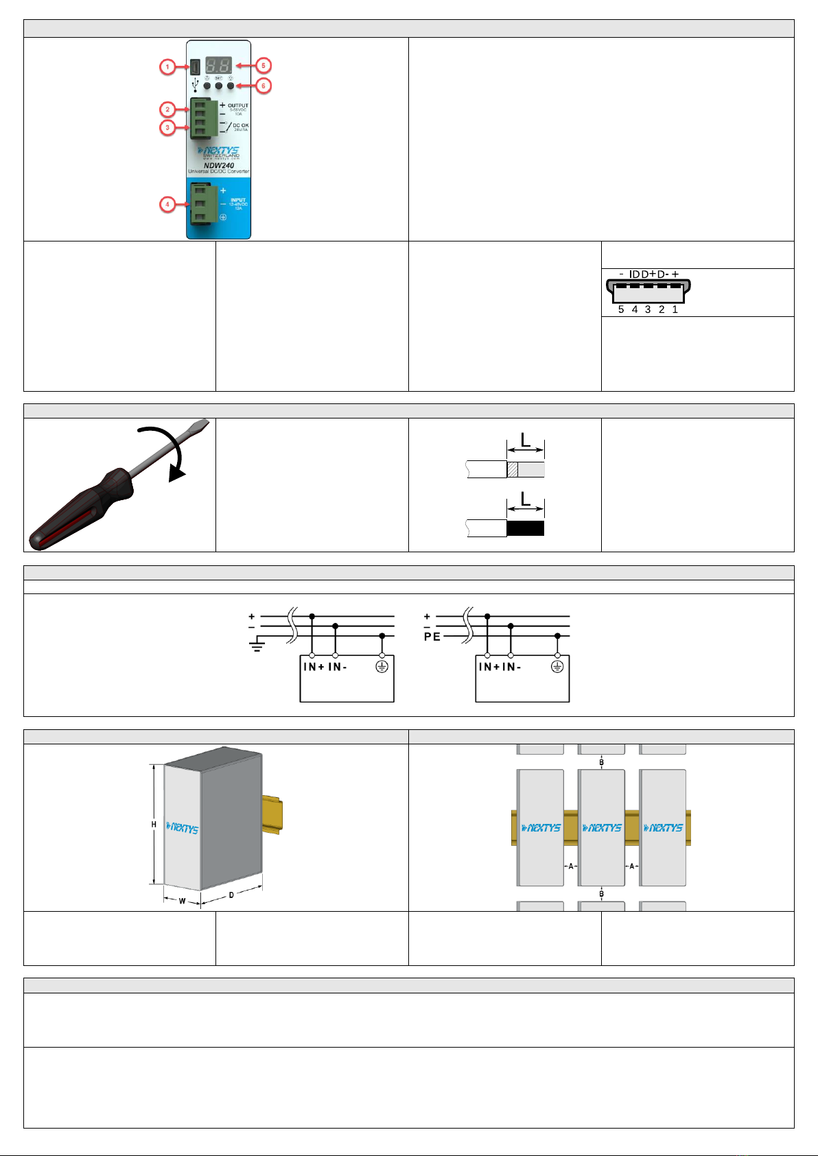
Connections and User interface
1. Modbus over USB: used to connect a device running POWERMASTER or custom
user application. Firmware update is also possible.
2. DC Output: connected to the load. The output voltage is adjustable between 5 to
55Vdc.
3. DC-OK dry contact: normally open relay contact is available; the relay closes
when the output voltage is >90% of the programmed output voltage value.
4. DC Input: input voltage supply, range is from 12 to 48Vdc.
5. Display: 2-digits LED display used to program the device and read its status.
6 Control keys: 3 push buttons are provided to navigate through menus and to
select various functions.
Input Connection:
▪+ = Positive DC
▪- = Negative DC
▪I= Earth ground
Output Connection:
▪+ = Positive DC
▪- = Negative DC
Auxiliary Connection:
DC OK: Dry contact
▪NO
▪COM
Mini USB-B Type
▪1 = VBUS (+5V)
▪2 = Data (D-)
▪3 = Data (D+)
▪4 = Not connected (ID)
▪5 = GND
Recommended connecting cable (Fig.5)
Recommended Tightening torque
0.5-0.6Nm
4.42-5.30 lbf in
Input / output connections
Solid: 2.5mm² / 12AWG
Stranded:2.5mm² / 12AWG
L: 6.0-7.5mm / 0.24-0.30in
Input connection
DC Line
Dimensions
Distances (Fig.3)
Dimension
W
D
H
mm
40.0
110.0
115.0
Distance
A
B
mm
20
50
INSTRUCTIONS
1) Description: NDW240 can be supplied with any voltage between 11Vdc and 55Vdc, please respect the polarity. The output voltage can be programmed to any
voltage between 5Vdc and 55Vdc.
To prevent damage in case of reverse polarity, the device is protected by an internal not replaceable fuse.
NDW240 can be used in SELV and PELV circuits.
2) Installation: use DIN-rails according to EN 60715. Installation should be made vertically (see Fig.4). For better device stability fix the rail to the wall close to the point
where the device is to be mounted. In order to guarantee sufficient convection, we recommend observing a minimum distance to other modules (see Fig.3).
The device is provided with a thermal protection, a limited air flow can cause the thermal protection tripping.
The device automatically restarts after cooling.
To get normal operation reduce the temperature of the air surrounding the unit, increase the ventilation or reduce the load.

3
3) Connections: the device is equipped with pluggable screw terminals. To avoid sparks, do not connect or disconnect the connectors before having previously turned-off
input power and waited for capacitors discharge.
In order to comply with local certification, use appropriate copper cables of indicated cross section, designed for an operating temperatures of:
60°C (for ambient up to 45°C)
75°C (for ambient up to 60°C)
90°C (for ambient up to 70°C)
Strip the connecting ends of the wires according to the indication on Fig.5 and ensure that all strands of a stranded wire enter the terminal connection.
4) DC Input protection: NDW240 is equipped with internal fuse, ratings of DC line protection devices must be coordinated with input current indicated on the data sheet.
5) Overload (OL) / short circuit (SC) / overvolatge (OVP) / overtemperature (OTP) protections: Hiccup auto-reset and constant current limitation, user selectable.
Overload behaviour in hiccup mode: the output current is limited at 1.5xImax. When the programmed Imax value is exceeded a timer is started. If the load current
demand is not reduced below Imax for maximum 5 seconds the output is switched off and kept off for 10 seconds.
Overload (OL) error message is shown on the display, this cycle is then repeated until the load current demand is not decreased below Imax.
Overload behaviour in constant current mode: the output current is limited at Imax. If the load asks for more current than Imax the output voltage is progressively
decreased to keep the output current regulated at Imax.
Short circuit behaviour: the output is switched off in about 0.2 seconds and kept off for 10 seconds. Short Circuit (SC) error message is shown on the display details. This
cycle is then repeated until the short circuit is removed.
Input/output overvoltage protection: the unit is protected against external overvoltage applied to the input; for input voltages greater than 62V the device will shut
down. In case of an internal failure, a double protection circuit switch off the output and avoid output voltage higher than 62V potentially dangerous for the supplied
devices.
Overtemperature protection: The “Over Temperature (Ot)” error message appears when the internal temperature exceeds the safe limits. In this case the output is
switched off. The output is switched back on when the temperature decreased to safe limits.
6) Status Signals:
“DC OK” relay contact(24V/1A):
Contact closes when the output voltage is present and within the product specified output voltage regulation range
7) Redundant and parallel connection: NDW240 is equipped with an internal ORing circuit allowing direct parallel connection for redundancy without the need of an
external isolating diode. Parallel connection for power increase can be achieved connecting the output of the devices in parallel. Please keep the length of the input and
output cables of the 2 paralleled units the same length and cross section to achieve the best possible current balancing. Avoid exceeding 80% of the total available
output current. To use parallel connection the operating mode shall be set to “Parallel (PA)” in the configuration menu.
10) Feeding DC motors: it is possible to feed DC motors considering that when a motor starts-up under effort its consumption is much higher than the nominal current
and it can trigger overcurrent protection.
NOTE: motors can generate high conducted noise on the DC line. Therefore it is not recommended to feed on the same line motors and equipment sensitive to noise.
11) Warranty: power supplies are guaranteed free from factory defects for the time specified in the “Sales Conditions”.
Failures caused by misuse, external and/or abnormal events (i.e. overvoltage, over temperatures) or non-respect of above parameters and standards, are not covered by
warranty.
Opening the housing of the product makes warranty to be no longer valid.
In order to improve the products Nextys SA reserves the right to change product specifications, ratings and data without previous advice.
Mounting / Dismounting Instructions (Fig.4)
For DIN rail mounting according to IEC 60715 TH35-7.5(-15). Mounting as shown in figure, with input terminals on lower side, with suitable cooling and maintaining a
proper distance between adjacent devices as specified in the User manual.
Mounting
1.Tilt the unit slightly backwards.
2.Fit the unit over the top edge of the rail.
3.Slide it downward until it hits the stop.
4.Press against the bottom for locking.
1
2
3
4
Dismounting
1.Pull down the slide clamp lever.
2.Tilt the unit upward.
3.Unhook the unit from the rail.
1 & 2
3
4
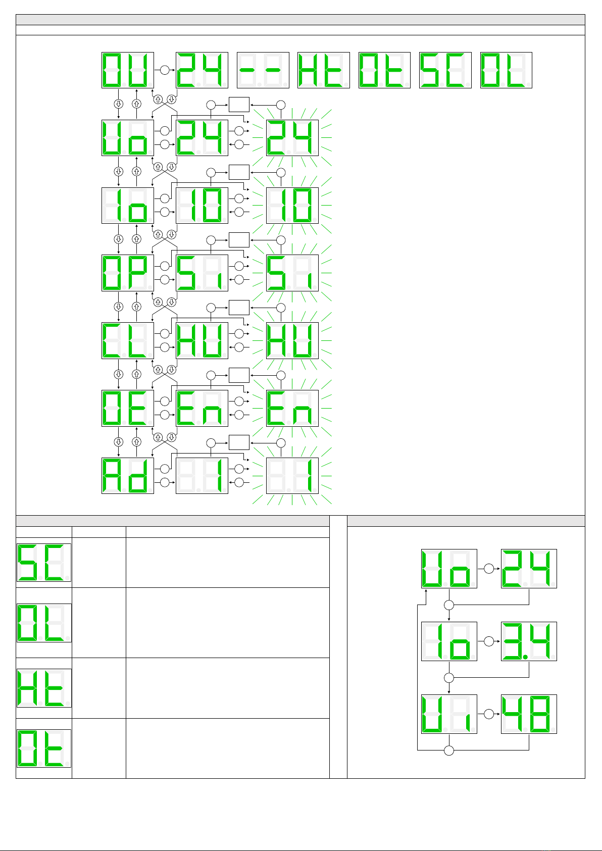
Menu navigation
The menu organization is presented in the following diagram. The various options are selected with the 3 control keys.
2s
2s
Set
2s
Set
Measures
and state
Output
voltage
Output
current
2s
Set
Operating
mode
2s
Set
Current
limit
2s
Set
Output
enable
Allowed values: 4.5...55.5V
Resolution: 0.01V
Default value: 5V
Allowed values: 1...11A
Resolution: 0.1A
Default value: 10A
Allowed values: Single (SI), Parallel (PA)
Default value: Single
Allowed values: Constant current (CC), Hiccup (HU)
Default value: Hiccup
Allowed values: Disabled (DI), Enabled (EN)
Default value: Enabled
Set
Set
(Store)
15s Output
measures (No store)
Set
Set
(Store)
(No store)
Set
Set
(Store)
(No store)
Set
Set
(Store)
(No store)
Set
Set
(Store)
(No store)
USB Powered High temperature Over temperature Short cucuit
2s
Set
Modbus
address Allowed values: 1...99
Default value: 1
(Store)
Set
Set
(Store)
(No store)
Output
measures
Output
measures
Output
measures
Output
measures
Output
measures
Overload
Measures
15s
15s15s
15s 15s
15s 15s
15s 15s
15s 15s
Alarm codes
Measures
Display code
Description
Behaviour
1s
1s
1s
Output
voltage
Output
current
Input
voltage
Set
Set
Set
Output
Short circuit
error
The “Short Circuit (SC)” error message appears when a
short circuit is detected at the output.
In this case the output is switched off and then restarted
after 10 seconds. This cycle is repeated until the short
circuit is removed.
Output
Overload
error
The “Overload (OL)” error message appears when the
output current exceeds Imax; it is only applicable when
“hiccup mode” current limitation is selected.
In this case the output is switched off after 5 seconds of
sustained overload and then restarted after 10 seconds.
This cycle is repeated until the output current is reduced
below Imax.
Over-
temperature
warning
The “Over Temperature warning (Ht)” appears when the
internal temperature is reaching unusually high levels. If
no modification of the ambient operating temperature
and / or load conditions is performed by the user, it is
highly possible that a “Over Temperature (Ot)” error
occurs, leading to the output switch off.
Over-
temperature
error
The “Over Temperature (Ot)” error message appears
when the internal temperature exceeds the safe limits. In
this case the output is switched off. The output is switched
back on when the temperature decreased to safe limits. In
case of repeated Over Temperature errors check the
device ventilation and/or reduce ambient temperature
Other nextys Media Converter manuals


Popular Media Converter manuals by other brands


Telco Systems
Telco Systems Metrobility 10/100 AutoTwister 2643-15-01 Installation & user guide

Axis
Axis P7210 user manual

Benchmark
Benchmark DAC1 HDR instruction manual

GoMax Electronics
GoMax Electronics MX-1010 user manual

Channel Master
Channel Master CM-7000 Troubleshooting

Lenz Elektronik
Lenz Elektronik Digital plus Silver 10331 manual