Calibre HQView-300 Series User manual

HQView-300 Series
Operating Instructions
Version 2.41

©Calibre UK Limited Issue 2.41 04th November 2013, W: www.calibreuk.com
This manual explains how to operate your HQView-300 Series (HQView-3xx) image scaler. The
HQView-300 Series comes in three versions HQView-300S, HQView-310 and HQView-320.
HQView-3xx is designed to provide users with a powerful and flexible method of driving large
display devices, and multiple screen applications including flexible geometry correction
functions.
If you have any queries relating to this or any other product supplied by Calibre please visit
our web site www.calibreuk.com.
(44) 1274 730960, for the attention of our Technical Support Department.
COPYRIGHT
This document and the software described within it are copyrighted with all rights reserved. Under
copyright laws, neither the documentation nor the software may be copied, photocopied, reproduced,
translated, or reduced to electronic medium or machine readable form, in whole or in part, without
prior written consent of Calibre UK Ltd ("Calibre"). Failure to comply with this condition may result in
prosecution.
Calibre does not warrant that this product package will function properly in every hardware/software
environment.
Although Calibre has tested the hardware, firmware, software and reviewed the documentation,
CALIBRE MAKES NO WARRANTY OR REPRESENTATION, EITHER EXPRESS OR IMPLIED,
WITH RESPECT TO THIS HARDWARE, FIRMWARE, SOFTWARE OR DOCUMENTATION, THEIR
QUALITY, PERFORMANCE, MERCHANTABILITY, OR FITNESS FOR A PARTICULAR PURPOSE.
THIS SOFTWARE AND DOCUMENTATION ARE LICENSED 'AS IS', AND YOU, THE LICENSEE,
BY MAKING USE THEREOF, ARE ASSUMING THE ENTIRE RISK AS TO THEIR QUALITY AND
PERFORMANCE.
IN NO EVENT WILL CALIBRE BE LIABLE FOR DIRECT, INDIRECT, SPECIAL, INCIDENTAL, OR
CONSEQUENTIAL DAMAGES ARISING OUT OF THE USE OR INABILITY TO USE THE
SOFTWARE OR DOCUMENTATION, even if advised of the possibility of such damages. In
particular, and without prejudice to the generality of the foregoing, Calibre has no liability for any
programs or data stored or used with Calibre software, including costs of recovering such programs or
data.
Calibre UK Ltd
Cornwall House, Cornwall Terrace
Bradford, West Yorkshire
BD8 7JS, England
Telephone +44 (0)1274 394125
Fax + 44 (0)1274 730960
Email techsupport@calibreuk.com
Web-site www.calibreuk.com
Copyright (c) 2013 All World-wide Rights Reserved
All trade marks acknowledged
Calibre operates a policy of continued product improvement, therefore specifications are subject to
change without notice as products are updated or revised.
E&OE.

©Calibre UK Limited Issue 2.41 04th November 2013, W: www.calibreuk.com
Contents
SAFETY WARNING: 1
INTRODUCTION 2
1.1. General Introduction 2
1.2. Packing List 3
HQVIEW-3XX SYSTEM DESCRIPTION 4
2.1. Product Overview 4
2.2. Product Specification 4
2.2.1. Power Supply Requirement 4
2.2.2. Component Video Inputs 4
2.2.3. Computer (SVGA) Inputs VESA formats 4
2.2.4. HDMI & DVI Inputs 4
2.2.5. Display Output 5
HQVIEW-3XX CONTROL 6
3.1. Menu Tree 6
3.2. Introduction 11
3.3. Main Menu 12
3.4. Input 12
3.5. Output 13
3.5.1. Output Mode 13
3.5.2. Location 13
3.5.3. Optimize for Display 13
3.5.4. DVI Range 13
3.5.5. Frame Rate 14
3.5.6. (Available) Frame Rates 14
3.5.7. I/O Lock 14
3.5.8. Native Color Temp 15
3.5.9. Output Gamma 15
3.6. Colour 15
3.6.1. Black-Level Offset 15
3.6.2. Black-Level 15
3.6.3. Contrast 15
3.6.4. Saturation 15
3.6.5. Hue 15
3.6.6. RGB values 16
3.6.7. Colour Temp 16
3.6.8. RGB values 16
3.6.9. Input Gamma 16
3.7. Geometry 16
3.7.1. Horizontal/Vertical Position 16
3.7.2. Edge Control 16
3.7.3. Warp 16
3.7.4. Picture Format 17
3.7.5. Aspect Ratio 17
3.7.6. Overscan 17
3.7.7. Pan Tilt Zoom 17
3.8. Enhancement 19
3.8.1. Sharpness 19
3.8.2. Detail 19
3.8.3. Video Filters 19
3.9. System 20
3.9.1. User 20
3.9.2. Names/Profiles 20
3.9.3. Input Config 20
3.9.4. Display Mode 21
3.9.5. Switching Transition 21
3.9.6. Menu Settings 21
3.9.7. Network Settings 21
3.9.8. Factory Defaults 22

©Calibre UK Limited Issue 2.41 04th November 2013, W: www.calibreuk.com
3.10. Multiple Unit 22
3.10.1. Auto Zoom 22
3.10.2. Units Wide/Units High 22
3.10.3. Horizontal Pos/Vertical Pos 22
3.10.4. Blend Width 23
3.10.5. Blend Curve Type 23
REMOTE CONTROL WEB SERVER 24
4.1. Introduction 24
4.2. Installing the Software 24
4.3. Discovery Tool 24
4.4. Software Operation 25
4.5. File Upload 25
FIRMWARE UPDATE 27
5.1. Introduction 27
5.2. Updating Firmware 27
ENVIRONMENTAL AND EMC 28
6.1. Recommended Operating Conditions 28
6.2. Storage 28
6.3. CE and FCC Compliance 28
6.4. PAT Testing 28

©Calibre UK Limited Issue 2.41 04th November 2013, W: www.calibreuk.com
SAFETY WARNING:
1. THERE ARE NO USER SERVICEABLE PARTS WITHIN THE UNIT. REMOVAL OF THE TOP COVER
WILL EXPOSE DANGEROUS VOLTAGES. DO NOT OPERATE THE UNIT WITHOUT THE TOP COVER
INSTALLED.
2. ENSURE THAT ALL ELECTRICAL CONNECTIONS (INCLUDING THE MAINS PLUG AND ANY
EXTENSION LEADS) ARE PROPERLY MADE AND COMPLY WITH ELECTRICAL SAFETY
REGULATIONS.
3. ENSURE THAT THE INTEGRITY OF THE EQUIPMENT ISOLATION BARRIER IS MAINTAINED WHEN
CONNECTING TO OTHER EQUIPMENT. THIS MEANS THAT ONLY LOW VOLTAGE ISOLATED
CIRCUITS MAY BE CONNECTED TO THE SIGNAL INPUTS AND OUTPUTS. IF ANY DOUBT EXISTS
CONSULT QUALIFIED SERVICE PERSONNEL.
4. TO PREVENT SHOCK OR FIRE HAZARD DO NOT EXPOSE THIS EQUIPMENT TO RAIN OR
MOISTURE. IF SUCH EXPOSURE OCCURS, REMOVE THE PLUG FROM THE MAINS OUTLET AND
HAVE THE EXPOSED UNIT CHECKED BY QUALIFIED SERVICE PERSONNEL.
5. DO NOT CONTINUE TO OPERATE THE EQUIPMENT IF YOU HAVE ANY DOUBT ABOUT IT
WORKING NORMALLY, OR IF IT IS DAMAGED IN ANY WAY. WITHDRAW THE MAINS PLUG FROM
THE MAINS OUTLET AND CONSULT QUALIFIED SERVICE PERSONNEL.
6. DO NOT REMOVE ANY FIXED COVERS UNLESS YOU ARE QUALIFIED TO DO SO AND EVEN THEN
WITHDRAW THE MAINS PLUG FROM THE MAINS OUTLET BEFORE YOU START.
7. THIS EQUIPMENT CONTAINS NO USER SERVICEABLE PARTS. REFER ALL SERVICING AND
MAINTENANCE TO QUALIFIED SERVICE PERSONNEL.
8. TO AVOID EXPLOSION, DO NOT OPERATE THIS EQUIPMENT IN AN EXPLOSIVE ATMOSPHERE

©Calibre UK Limited Issue 2.41 04th November 2013, W: www.calibreuk.com
INTRODUCTION
1.1.
General Introduction
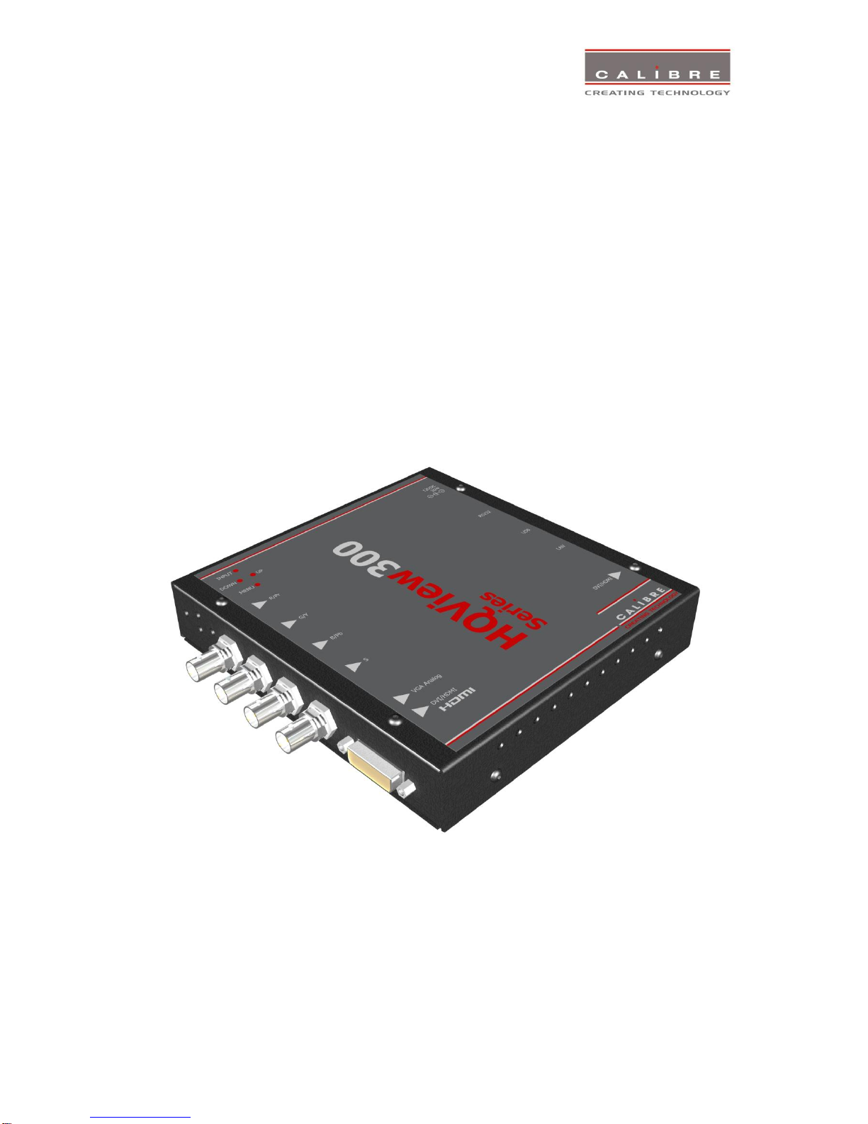
HQView-3xx is a very flexible image scaler developed specifically for driving large screen displays and
multiple screen applications from video or graphics sources.
HQView-3xx features state of the art digital image processor which provides market leading HD& SD
per-pixel multiple Iow-angle motion-adaptive de-interlacing and automatic film pull-down correction for
3:2 and 2:2, significantly outperforming the capabilities of benchmark competitor products.
HQView-3xx features excellent image processing algorithms for the very best scaling, film and video
noise reduction and MPEG artefact reduction.
HQView-3xx uses a very flexible high performance video input front end including true component video
support in analogue YPbPr and RGBS formats. HDMI and DVI video with HDCP encryption is also
supported, as are computer graphics inputs in VGA/SVGA analogue and HDMI/DVI digital formats.
The output format can be set to I/O Lock mode where it locks the output frame rate to the input frame
rate dynamically without frame rate conversion so as to reduce system latency, or it can be set to a fixed
output frame rate for driving basic screens which are not 50Hz-compatible. Furthermore, the HQView-
3xx can be set to have the output resolution match the input resolution to preserve aspect ratio.
A Low latency mode with non-motion adaptive reduced processing is available to further reduce latency.
Outputs are available in DVI digital formats. Note that if an HDCP encrypted signal is connected to the
HDMI or DVI input, the DVI output signal will be similarly HDCP encrypted.
HQView-3xxV2 supports Pan, Zoom and Tilt to select a part of the input image, fill the screen and pan
within it.
System control is via an OSD controlled by keys on the front panel or through the inbuilt TCP/IP web
server.
Additionally a free API manual is published on our website at the link given below to allow the use of the
LAN or RS232 remote control ports.
http://www.calibreuk.com/documents/hqview/HQView_LEDView%20API%20Protocol_v2.02%20Generic
.pdf
HQView-3xx can be operated with different firmware. At time of issuing this document three firmware
options are available. Each firmware provides different feature sets controlled through the OSD. Thus,
the OSD menu systems of the firmware options may deviate from each other. Special emphasize is
given in the discussion of the OSD menu system in the corresponding chapters.
In the basic configuration HQView-300S is used for single display installations without a need for
geometry correction.
The next stage is the HQView-310 for multiscreen or multi projector installations featuring Auto Zoom
and Edge Blend, as well as embedded warp functions for geometry correction.
Edge Blend allows to electronically reduce the brightness level of certain image regions to match the
brightness of overlapping areas.
Auto Zoom automatically crops and zooms the input video image to display the section of the total
image on the corresponding projector or screen.
Embedded warp functions allows adjustment of the image in a projection scenario to match a rotated,
tilted or curved screen. For 9:16 portrait mode signage special predefined warp maps are available to
rotate and stretch a video image to fill a +/-90° rotated display panel.
HQView-320 also features free form warp capability for non-flat screens in single or multi projector
installation. Warp maps created with the PC tool “Warp Generator” can be uploaded into HQView-320.
HQView-320 is supported by 3rd party PC based auto calibration software creating such warp maps
using camera captured information.

©Calibre UK Limited Issue 2.41 04th November 2013, W: www.calibreuk.com
1.2.
Packing List
HQView-3xx is supplied with the following:
1) This manual
2) 3 pin plug IEC mains cable
3) DVI-D output cable
4) CD containing manuals and useful applications

©Calibre UK Limited Issue 2.41 04th November 2013, W: www.calibreuk.com
HQVIEW-3XX SYSTEM DESCRIPTION
2.1.
Product Overview
HQView-3xx is designed to accept the following input signals:
YPbPr or RGBS SD/ED/HD component video via 3 or 4 BNC connectors
VGA analog (computer interface) via 15HDD
DVI (Digital Visual Interface) via DVI-I (only the digital part is implemented on this connector), HDMI
is supported via a HDMI/DVI adapter.
2.2.
Product Specification
This section provides technical details for all possible inputs.
Please note that not all possible input options may be applicable to certain output modes.
2.2.1.
Power Supply Requirement
12V DC table top power supply requiring a 100V-264VAC 50/60Hz mains connection.
2.2.2.
Component Video Inputs
Via 3 or 4 BNC connectors
YPbPr, YPbPrS, RGsB and RGBS component video, menu selectable.
Signal formats 484i (480i) and 576i (SD), 480p, 576p (ED), 720p, 1080i at 50, 59.94 and 60Hz and
1080p at 24, 25, 29.97 and 30Hz.
Please note this input does not support Computer SVGA signals which should be connected via the
Computer SVGA input.
2.2.3.
Computer (SVGA) Inputs VESA formats
Signal formats: DOS, VGA –WUXGA up to 165MHz pixel clock
RGB video level 0.7V - 1.0V
RGB input impedance 75 Ohms
Sync format Separate H & V sync at TTL/5V levels.
2.2.4.
HDMI & DVI Inputs
DVI-D input with or without HDCP
HDMI 1.3 with or without HDCP through a DVI/HDMI adapter, 36-bit video compatible.
HDCP compatibility can be turned off for use with MAC computers.
Signal formats -video
484i and 576i (SD) in double-rate formats (1440 pixels per line), 480p, 576p (ED), 720p, 1080i at 50,
59.94 & 60Hz, 1080p at 24, 25, 30, 50, 59.94 & 60Hz.
Signal formats –computer
DOS, VGA –WUXGA up to 165MHz pixel clock

©Calibre UK Limited Issue 2.41 04th November 2013, W: www.calibreuk.com
2.2.5.
Display Output
A DVI-I connector is provided which will support DVI outputs as well as HDMI 1.3 with 36-bit video and
HD audio formats when connected to a suitable HDMI 1.3 receiver. When the input signal has HDCP
encryption, the DVI-D output connector will carry a similarly HDCP encrypted signal. When an HDCP
encrypted signal is input, but the display device does not support HDCP, the output image will
turn black and a message indicating HDCP Signal will come up to indicate this.

©Calibre UK Limited Issue 2.41 04th November 2013, W: www.calibreuk.com
HQVIEW-3XX CONTROL
3.1.
Menu Tree
HQView-300S Menu Tree
1st Level
2nd Level
3rd Level
4th Level

©Calibre UK Limited Issue 2.41 04th November 2013, W: www.calibreuk.com

©Calibre UK Limited Issue 2.41 04th November 2013, W: www.calibreuk.com

©Calibre UK Limited Issue 2.41 04th November 2013, W: www.calibreuk.com

©Calibre UK Limited Issue 2.41 04th November 2013, W: www.calibreuk.com
HQView-310 as well as HQView-320 have an additional Warp and Multiple Unit Menu.
1st Level
2nd Level
3rd Level
4th Level
HQView-320 has an additional Discrete Warp Map Item.
1st Level
2nd Level
3rd Level
4th Level

©Calibre UK Limited Issue 2.41 04th November 2013, W: www.calibreuk.com
3.2.
Introduction
The HQView-3xx units have the input connectors on one side of the housing and the output connector
and communication ports on the opposite side. The keypad for controlling HQView-3xx is located on the
input connectors side. The active input is indicated by their corresponding triangles lit green.
1 –Keypad with three keys for OSD menu navigation (Menu, Down and Up) and a key for input channel
selection (Input).
With the Menu key the OSD menu is activated. The up/down keys are used for OSD menu navigation.
To exit the OSD menu or any submenu navigate go to the Exit item and press the menu key. To access
a submenu navigate to it and press the menu key. To apply a change go to the menu item, press the
menu key and make a parameter change with the up/down key. Confirm the change by pressing the
Menu key. This will also bring you back to the submenu.
By pressing the Input button multiple times the available input channels are toggled through. The active
channel is indicated by the associated green lit triangle(s). The exception is that the test patterns are
selected through the menu/input
With the following multiple key presses further functions can be applied:
Keypad unlock: Up/Down
Set output and fallback output mode to VGA: Menu/Up
Mode reset: Menu/Down
Factory reset: Menu/Up/Down
2
3
4
5
6
7
8
1

©Calibre UK Limited Issue 2.41 04th November 2013, W: www.calibreuk.com
A factory reset can also be applied when pressing the factory reset key combination at power up. The
keys have to be kept pressed for about 10 seconds until the RGB(S) input LEDs stop flashing. If the
keys are released during that 10 seconds period the system will get into Updater mode (see chapter 5)
since the Menu key is part of this key combination.
2 –YPbPr / RGB(S) video input
3 –DVI-I connector featuring a DVI-D input and a VGA input
4 –DVI-I output connector (only the digital DVI-D is supported, HDMI 1.3 receivers can be connected
with a DVI/HDMI adapter cable)
5 –TCP/IP port
6 –USB port
7 –RS232 port
8 –Power supply connector
3.3.
Main Menu
The main menu lists the input channel select item, 6 sub menus, and a menu item for automatic setup
of VGA modes. The 6 sub menus are Output, Color, Geometry, Enhancement, System and Multiple Unit
(only HQView-310 and HQView-320).
On each menu page an Exit menu item is available to leave the menu or submenu.
The menus are contextual, therefore some adjustments are not applicable to all signal types or
operating modes, in which case those non-applicable functions will be ghosted/ greyed out and are not
accessible.
All menus have a top status line and a bottom line indicating the firmware revision number. In the status
line the currently selected input channel is indicated and the detected mode is identified. The firmware
revision number displays the revision number of the boot-loader behind BL, the revision number of the
firmware behind FW and the model 300S, 310, 320 type of the unit.
To set up your HQView-3xx it is recommended that you follow this procedure:
Choose the correct output mode and parameters to suit your screen or projector.
Select the correct input signal.
Set the input levels and features appropriately to optimize the appearance of your image.
Set any other parameters to suit your application.
Note: All Input parameters are specific to your chosen input channel and input signal type, they are not
global to the unit. All Output parameters are global
3.4.
Input
The list of available inputs can be scrolled through using the Up and Down keys. The new input is not
selected until the Menu key is pressed.
The list of inputs are: Component, VGA, DVI and Test Pattern.
Test patterns can be generated by HQView-3xx without needing an input connected. When Test Pattern
is selected as the input, the required test pattern can be chosen with the menu navigation up/down keys
when the menu system has been exited, or it can be selected in menu/System/Input Config/Test Pattern
Setup.

©Calibre UK Limited Issue 2.41 04th November 2013, W: www.calibreuk.com
3.5. Output
This menu contains adjustments associated with setting up outputs from the unit. Most items are
collected in the Display Type submenu. Use the up and down keys to scroll to the required item and
press the Menu key.
3.5.1. Output Mode
Settings: 640x480, 800x600, 1024x768, 1280x768, 1280x800, 1280x1024, 1360x768, 1366x768,
1400x1050, 1440x900, 1600x1200, 1680x1050, 1920x1200, 720p (1280x720), 1080p (1920x1080),
480p (720x480), 576p (720x576)
Set up the desired output resolution with output mode. The output mode setting should match the native
resolution of the imaging device to avoid double scaling.
When the system is not in scale but aspect ratio preserve mode –which can be set up under the
Geometry menu –this setting will become the Fallback Output Mode. If the system cannot provide an
output resolution to match the input resolution it will use the Fallback Output Mode instead. Also, if there
is no input video signal detected the output will be run at this Fallback Output Mode.
3.5.2. Location
Settings: Front Tabletop, Front Ceiling, Rear Tabletop, Rear Ceiling
The image can be flipped to accommodate different projection scenarios as well as screens mounted
upside down.
3.5.3. Optimize for Display
Settings: DVI forced, Optimized, DVI/HDMI
Internally, the display interface processes data at a full ten bits per colour. The colour depth on the DVI-
D output is determined by the supported standard of the attached monitor or device when set to
DVI/HDMI. For DVI 1.0 and HDMI 1.1/1.2 devices it is 24 bit, for HDMI 1.3 compliant devices it is up to
36 bit.
DVI forced will output with 24 bit colour depth irrespective of the supported standard of the attached
monitor.
When the Optimized setting is enabled the output resolution is automatically set to the native screen
resolution of the attached display by reading the EDID of the display.
3.5.4. DVI Range
Settings: Default, Limited, Full
When set to Default CEA output modes have limited range, and VESA modes have full range.
Therefore, an incoming limited range mode is either passed through when the output is set to a CEA
output mode or expanded when the output is set to a VESA mode. An incoming full range mode is either
compressed when the output is set to a CEA output mode or passed through when the output is set to a
VESA mode.
If the HDMI/DVI output does not behave as expected, e.g. because the HDMI display is not evaluating
AVInfoFrames properly, the range can be changed manually.
A limited video range is only using the following greyscale for video information - 8 Bit System: 0x10 ..
0xEF, 10 Bit System: 0x040 .. 0x03BF, 12 Bit System: 0x100 .. 0xEFF.

©Calibre UK Limited Issue 2.41 04th November 2013, W: www.calibreuk.com
3.5.5. Frame Rate
Settings: 60 Hz, 50 Hz, 48 Hz, 24 Hz, Auto
In auto mode the output frame rate follows the input frame rate as configured in the Frame Rates menu.
Signals with 24Hz, 25H, 48Hz, 50Hz input modes get special treatment, modes with other refresh rates
are displayed at 60Hz.
24Hz input modes will be output at 24Hz if the output resolution is set to either 720p or 1080p and the
Frame Rate setting in the Output Config menu includes 24Hz, otherwise it is displayed at twice the rate
if the Frame Rate setting in the Output Config menu includes 48Hz.
Otherwise a 24Hz input mode is displayed at 60Hz. 48Hz input modes will be output at 48Hz if the
Frame Rate setting in the Output Config menu includes 48Hz.
Otherwise it is displayed at 50Hz.
A 25Hz input mode is output at twice the frame rate 50Hz.
An exception to the 24/25Hz input mode treatment is if the output resolution is set to 480p. 480p is
always run at 60Hz output rate.
50Hz input modes are displayed at 50Hz output rate.
The output frame rate can also manually set to 24Hz, 48Hz, 50Hz or 60Hz if possible, i.e. such output
modes are available.
Only 720p and 1080p output modes are available with 24Hz refresh rate.
The 480p output mode is only available at 60Hz refresh rate.
For all other modes 48Hz, 50Hz and 60Hz refresh rate is available.
3.5.6. (Available) Frame Rates
Settings: 60/50 Hz, 60/50/24 Hz, 60/50/48, 60/50/24/48
Limits the possible output frame rates that can be selected. It is primarily to be able to limit the choices
available for the Auto refresh rate configuration.
3.5.7. I/O Lock
Settings: Off, Auto
If I/O Lock is switched off the output is run with a fixed refresh rate determined by the frame rate setting,
which deviates from the input refresh rate, even if both are nominally at the same rate. This causes
occasional frame dropping or repeat.
If I/O Lock is set to Auto the output refresh rate is following the input video refresh rate if locking is
possible.
Locking is achieved by modulating the output clock and works if input and output refresh rate are
nominally at the same rate, e.g. when frame rate is set to 60Hz and the video input is also 60Hz.
If e.g. the video input rate is 50 Hz and the Frame rate is set to 60Hz, the output will enter free run
mode.
When Frame Rate is set to Auto the matching frame rate is chosen.
The status line of the OSD window under Sync Mode indicates if the output signal is locked to the input
signal (I/O Locked) or in free run mode (Free Run).

©Calibre UK Limited Issue 2.41 04th November 2013, W: www.calibreuk.com
3.5.8. Native Color Temp
Settings: 5500, 6500, 7500, 9300, 10000
Native Colour Temp allows the user to select from pre-configured colour temperatures to match the
display. If both Native Colour Temp set here in the Output menu and Colour Temp set in the Colour
menu are set to the same value, no conversion is performed.
3.5.9. Output Gamma
Settings: 1.0 to 3.0 in steps of 0.1
Output gamma allows to re-gamma video signals with pre-configured gamma values to match the
display. Input gamma and output gamma both default to 2.2. If they are both set to the same value,
there is no effect on the image.
Note: If e.g. an adjustment to reduce the level of red in the image is required, select a higher number for
the (input) Colour Temp in the Colour menu, or a lower number for the Native Colour Temp in the
Output menu.
3.6. Colour
This menu contains adjustments associated with setting up inputs to the unit. Use the Up and Down
keys to scroll to the required item and press the Menu key.
3.6.1. Black-Level Offset
Available Settings: 0 IRE, 7.5 IRE
Used to select 7.5 IRE black level set-up adjustment. Should always be set to 7.5 IRE for HDMI video
inputs.
3.6.2. Black-Level
Settings: -50 to 50 in steps of 1
Black level controls the offset applied to the video signal.
3.6.3. Contrast
Settings: -50 to 50 in steps of 1
Contrast controls the gain applied to the video signal.
3.6.4. Saturation
Settings: -50 to 50 in steps of 1
Control of video saturation, applies to all video inputs but not computer input signals or formats.
3.6.5. Hue
Settings: -50 to 50 in steps of 1
Control of video hue, applies to all video inputs but not computer input signals or formats.

©Calibre UK Limited Issue 2.41 04th November 2013, W: www.calibreuk.com
3.6.6. RGB values
This is a user-defined colour temperature setting whereby individual R,G,B gain and offset (bias) can be
set so as to accurately calibrate a particular input to the display device.
3.6.7. Colour Temp
Settings: 5500, 6500, 7500, 9300
Colour Temp allows the user to select from pre-configured colour temperatures to match the colour
temperature of the incoming signal. If both Colour Temp set here in the Colour menu and Native Colour
Temp set in the Output menu are set to the same value, no conversion is performed.
3.6.8. RGB values
This is a user-defined color temperature setting whereby individual R,G,B gain and offset (bias) can be
set so as to accurately calibrate a particular input to the display device.
3.6.9. Input Gamma
Settings: Gamma 1.0, Gamma 1.5, Gamma 2.2, Gamma 2.8
Set this value to match the native gamma of the input signal. Input gamma and output gamma both
default to 2.2. If they are both set to the same value, there is no effect on the image.
3.7. Geometry
This menu contains adjustments associated with setting up position, aspect ratio and scale of the input
signal. Scale can be as simple as an overscan up to arbitrarily warping the image.
3.7.1. Horizontal/Vertical Position
Settings: in steps of 1 pixel/line
Change the positional values to match the display boarders.
3.7.2. Edge Control
Submenu for changing the position of the image edges, effectively scaling the image in horizontal and
vertical direction. HQView-310 and 320 have some limitations compared to HQView-300 regarding
value range, due to the use of the warp engine for scaling and auto zoom.
3.7.3. Warp
Submenu for warping the image and defining projection condition. The projection condition can be Front
Table top, Front Ceiling, Rear Table top or Rear Ceiling. The corresponding image flip is applied on top
of the following warp applications.
The warp applications are Keystone, 4-Corner, Rotation, and PC. Special portrait warp applications for
clockwise (90°) and counter-clockwise (270°) rotation with scaling are provided as well.
Under the Keystone application the image can be adjusted to match a horizontally and vertically tilted
screen. Also, Pin/Barrel distortion of the lens or screen can be adjusted simultaneously.
Under the 4-Corner application all corners can be moved and the image is calculated to fit into the given
trapezoid.
Table of contents
Other Calibre Media Converter manuals

Calibre
Calibre LEDView-510 User manual

Calibre
Calibre FoveaHD User manual

Calibre
Calibre VideoExcel User manual

Calibre
Calibre HQView-2xx Series User manual

Calibre
Calibre HQView-400S User manual

Calibre
Calibre HQView-100S User manual

Calibre
Calibre HQView-500 Series User manual

Calibre
Calibre HQView620 User manual

Calibre
Calibre HQView-325 User manual