ermengineering DC-200 User manual

Use and maintenance manual
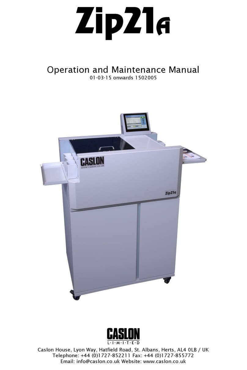
Automatic die cutter
Model: DC-200
____________________________________________________________________________________________________________________
www.ermengineering.com info@ermengineering ✆(+34)937632525
P a g . 1
(Original) Use and maintenance manual
Type: Automatic die cutter 2000mm
Model: DC-200
IMPORTANT
Read this user manual and follow the instructions and warnings before operating this device.
Any modification or transformation performed on this machine may cause loss of the
manufacturer’s guarantee and liability.
This manual must always remain near to the machine and visible to all the operating and
maintenance staff, for any future consultation, forming part of the equipment.

Use and maintenance manual
Automatic die cutter
Model: DC-200
____________________________________________________________________________________________________________________
P a g . 2
Index:
Page
-CE Declaration of conformity:........................................................................................... ¡Error! Marcador no definido.
-Description: ..................................................................................................................................................................................4
-Technical characteristics:........................................................................................................................................................4
-Installation and connection....................................................................................................................................................4
-Using instructions: .....................................................................................................................................................................6
Safety systems and messages. ............................................................................................................................................................................. 7
Programming ............................................................................................................................................................................................................ 8
Belt cutting measures for the different dies:................................................................................................................................................. 9
DIE CUTTING A-A Direct finger.......................................................................................................................................................................... 9
DIE CUTTING A-A Finger over finger .............................................................................................................................................................13
DIE CUTTING A-B for High profile belts at 90º ..........................................................................................................................................16
DIE CUTTING A-B Diagonal 70º.......................................................................................................................................................................18
Changing die head .................................................................................................................................................................................................20
-Care and maintenance ........................................................................................................................................................... 21
-Troubleshooting ...................................................................................................................................................................... 22
-Pneumatic drawing................................................................................................................................................................. 24
-Spare parts ................................................................................................................................................................................. 25
-Electrical drawing ................................................................................................................................................................... 31

Use and maintenance manual
Automatic die cutter
Model: DC-200
____________________________________________________________________________________________________________________
P a g . 3
-CE Declaration of conformity
WE DECLARE, under our responsibility, that the machine:
- Type: Automatic die cutter
- Brand: ERM Engineering
- Model: DC-200
- Serial No.: xxxxxx
- Manufacturer date: 2021
Inspired by the directives of the Official Journal of the European Communities:
2006/42/CE Machinery Directive
2014/35/UE Low Voltage Directive
2014/30/UE Electromagnetic Compatibility Directive
Complies with the design and construction specifications of the European Standards on General
Machine Safety:
EN 349 –EN 614-1 –EN 614-2 –EN 1005-1 –EN 1005-2 –EN 1005-3 –EN 1005-4 –EN
14118 - EN 12100–EN 13850 –EN 13857 –EN 14118 - EN 14120 –EN 60204-1 –EN
11161 –EN 61310-1 - EN 13849-1 –EN 13849-2 –EN 60204-1
General Manager: Eduardo Ramos Martínez
Arenys de Munt (Barcelona)-SPAIN
Date: 2021/08

Use and maintenance manual
Automatic die cutter
Model: DC-200
____________________________________________________________________________________________________________________
P a g . 4
-Description:
Pneumatic die cutter with motorised head to cut conveyor belts in zigzag, with ball screw
activated by a stepper motor and positioning control. Pressure and die cutting time control.
Exchangeable cutting heads for different cutting geometries, with possibility of programming
diverse forward steps.
Support bench with material positioning guides.
This die cutter is especially designed to cut thermoplastic materials with interior tissue.
-Technical characteristics:
Dimensions 2677x930x1160 (l x w x h)
Weight 315 Kg
Max. Thickness 8 mm.
Voltage 1x230V
Power 0.40kW
Max. pressure 7 bar
-Installation and connection
Place the machine near the measuring table, or right after it, in order to avoid the material to be
cut coming into contact with the ground.
Leave 1 metre free on the four sides to facilitate personnel access when operating.

Use and maintenance manual
Automatic die cutter
Model: DC-200
____________________________________________________________________________________________________________________
P a g . 5
Level and balance the machine by means of the regulation bolts on the rubber feet.
Provide compressed air through a tube with minimum interior diameter of 8 mm. connected to
the intake.
NOTE: We must bear in mind that air consumption by this die cutter is 220 litres/minute
We shall connect the power cable to the control board at 230v. monophasic.

Use and maintenance manual
Automatic die cutter
Model: DC-200
____________________________________________________________________________________________________________________
P a g . 6
NOTE: It is recommended that the two supplies of air and power be run, hanging from
above, to prevent personnel tripping or falling.
-Using instructions:
WARNING:
THIS DEVICE INVOLVES THE HAZARD OF HANDS AND ARMS BEING TRAPPED BY THE
MOVEMENT OF THE CUTTING HEAD
GREAT CARE MUST ALSO BE TAKEN BETWEEN THE CUTTING HEAD AND THE SUPPORT
PLATE, AS THERE IS A DANGER OF CUTTING LIMBS.
Once the machine is connected to the mains and provided with air, we shall proceed to start it up
using the ON switch.

Use and maintenance manual
Automatic die cutter
Model: DC-200
____________________________________________________________________________________________________________________
P a g . 7
We shall check that the regulator pressure is between 2 and 6 bar.
Safety systems and messages.
This die cutter has been equipped with the following safety systems:
1- EMERGENCY STOP
This system allows an emergency stop to be performed at any time using the two push
buttons located at both ends of the bench.
MESSAGE: EMERGENCY BUTTON PRESSED
To deactivate it, we must unlock the push button and then press RESET to return the head to
the starting point.
CLAMP OPEN
This device does not allow engagement of the cutting head if the bar holding the belt is not
lowered.
MESSAGE: CLAMP OPEN
To deactivate it, all we need is to lower the bar and press START.
3- DOOR OPEN
This device detects that the rear door of the blade head is open.
MESSAGE: COVER OPEN

Use and maintenance manual
Automatic die cutter
Model: DC-200
____________________________________________________________________________________________________________________
P a g . 8
The door must be closed to deactivate it.
4- CYLINDER DETECTOR
This device does not allow displacement of the head because it detects that the cutting
cylinder is not raised. This may happen due to lack of air or failure of the detector.
MESSAGE: CYLINDRE WRONG
To deactivate it, provide the machine with air or replace the detector.
Programming
We must know the functions of the push buttons on the board to program the die cutter.
1- RESET
This must be pressed after an emergency stop or position the head at the starting point after
STOP.
2- A-A
- Selection of the A-A program
This program is used in the majority of cases, to always operate on the left guide rail and cut
the belts performing the first end with the coverage on top and the second end with the
fabric on top, both for direct finger die cutting as well as finger over finger die cutting.
3- A-B
- Selection of the A-B program
This program is only used in cases of diagonal belts, or belts with an hi profile, to operate the
first end on the left guide rail and the second on the right guide rail, always with the
coverage on top.

Use and maintenance manual
Automatic die cutter
Model: DC-200
____________________________________________________________________________________________________________________
P a g . 9
4- STOP
Allows the cutting process to be halted at any moment, to change the time or cutting
pressure, for example.
On pressing START, it will continue the process without losing the positioning memory
5- START
Starts the cutting process or acts to reboot following a stop.
6- WIDTH
We shall use this button to program the width of the belt in centimetres with the numerical
keyboard, to accept the number entered push ENTER.
7- STEP
We shall press this button to program the cutting process by means of the head assembled,
with the numerical keyboard, introduce the value in milometers, between 3mm to 50mm, to
accept the numerical value, press ENTER
8- TIME
We shall press this button to program the cut time using the numerical keyboard the
numbers accepted are between 3 to 10, to accept the number press ENTER
9- ESC
We shall use this key to correct or delete any wrong number when programming
Belt cutting measures for the different dies:
80 x 10 90º………………….......................................……100 mm. Longest
80 x 10 70º…………………….......................................…100 mm. Longest
120 x 15 90º…………………....................................……130 mm. Longest
50 x 20 finger over finger 90º………………………120 mm. Longest
DIE CUTTING A-A Direct finger
First, we place the first end of the belt on the left side by the guide rail with the coverage on top
and position the end of the belt just by the O Ref. mark.

Use and maintenance manual
Automatic die cutter
Model: DC-200
____________________________________________________________________________________________________________________
P a g . 10
We then mark the measure to input the relevant material with a pencil, according to the die we
want to use.
We then place the belt under the tread bar until the mark made matches up with 0 Ref. and we
make sure it is fully in contact with the guide rail.
We lower the tread bar by pressing the down button.

Use and maintenance manual
Automatic die cutter
Model: DC-200
____________________________________________________________________________________________________________________
P a g . 11
We select function A-A if it is not activated.
We press WIDTH to input the numerical value of the width of the belt in centimetres and accept
pressing ENTER.
We check that the STEP is correct. If it is not, we use the STEP key and input the desired value
after ENTER.
NOTE: The values programmed shall not be lost, even when the equipment is switched off;
the program always memorises the last values input.
We press START to begin cutting at the first end.
NOTE: During the cutting process, no programmed value may be changed, except the
cutting time. To do so, we press STOP and change that value pressing TIME, modifying the
cute time and accept pressing ENTER.
After we press START to continue.
Once the first cut is completed, we release the belt by pressing the raise bar button.

Use and maintenance manual
Automatic die cutter
Model: DC-200
____________________________________________________________________________________________________________________
P a g . 12
We place the second end of the belt on the left side by the guide rail, but the opposite way, that is,
with the coverage down, and position the end of the belt just on the O Ref. mark.
Then mark the measurement to feed in the material with a pencil, according to the die one
wishes to use.
We then feed in the belt under the holding bar until the mark made aligns with 0 Ref. and we
make sure it is fully in contact with the guide rail.

Use and maintenance manual
Automatic die cutter
Model: DC-200
____________________________________________________________________________________________________________________
P a g . 13
We lower the tread bar using the down push button and press START.
Once the operation is completed, we release the material by raising the tread bar.
DIE CUTTING A-A Finger over finger
NOTE: For this type of die cutting, one requires prior separation of the fabrics with the ply
separator device PS-15
Separate the fabrics of the 130 mm. belt at both ends.
We mount the 50x20 mm die.
We check that the A-A function is activated.
We program STEP 20 mm. and the required width in centimetres.
We shall regulate the pressure to 3 bar, as the cutting pressure is less due to the length of the
blades.
We place the first end of the belt on the left side, by the guide rail, and place the end of the belt
just on the O Ref. mark.

Use and maintenance manual
Automatic die cutter
Model: DC-200
____________________________________________________________________________________________________________________
P a g . 14
Then pencil mark the two measures to insert the material for the stops STEP-1 and STEP-2.
We then insert the material up to the first mark STEP-1.
We lower the tread bar using the push button to lower it and press START.
Once the first cutting operation has ended, we shall withdraw the surplus material.
We shall place the anti-cut plate between the two cloths up to the end of the separator cut.

Use and maintenance manual
Automatic die cutter
Model: DC-200
____________________________________________________________________________________________________________________
P a g . 15
Once the anti-cut plate has been placed inside, we insert the material up to the second mark
STEP-2.
We reduce the cutting pressure to 2 bar, as the second cut shall only cut the top fabric.
We lower the tread bar and press START.
On finishing the second cut, we withdraw the surplus material and the anti-cut plate.

Use and maintenance manual
Automatic die cutter
Model: DC-200
____________________________________________________________________________________________________________________
P a g . 16
We place the second end of the belt with the opposing face upward on the same left side and
repeat the same operations.
DIE CUTTING A-B for High profile belts at 90º
We select function A-B if it is not activated.
We mount the die chosen: 80x10 or 120x15.
We program the relevant gauge for the die mounted and program the width in centimetres.
We adjust the cutting pressure according to the hardness of the belt and the blade length.
First, we place the first end of the belt on the left side by the guide rail and then position the end
of the belt just by the O Ref. mark, in order to mark the relevant material insertion measurement
according to the die we wish to cut with.

Use and maintenance manual
Automatic die cutter
Model: DC-200
____________________________________________________________________________________________________________________
P a g . 17
We then place the belt under the holding bar until the mark made aligns with 0 Ref. and make
sure that it is fully in contact with the guide rail.
We lower the tread bar using the down push button.
Using the + / - buttons, we adjust the belt width in centimetres and press OK.
We check that the STEP is correct and, if that is not the case, using the MENU key, we jump to the
field STEP and input the desired value with + / - and then OK.
We press START to start cutting at the first end.
Once the first cut has been performed, we observe that the head shall be positioned at point 0 of
the end opposite the control board. On reaching that point, we release the belt by pressing the
bar up button.
We place the second end of the belt on the right side next to the right guide rail and, with the
coverage also on top, we position the final end of the belt just at the O Ref. mark, to pencil the
mark with the measurement for insertion of the relevant material according to the die we wish
to cut with.

Use and maintenance manual
Automatic die cutter
Model: DC-200
____________________________________________________________________________________________________________________
P a g . 18
We then place the belt under the holding bar until the mark made matches 0 Ref. and we make
sure it is fully in contact with the guide rail.
We lower the tread bar using the down push button and press START.
Once the operation has ended, we release the material by raising the pressing bar.
DIE CUTTING A-B Diagonal 70º
We select the A-B function if it is not activated.
We mount die 80x10 70º.
We program the STEP to 10mm.
We adjust the cutting pressure to 4 // 6bar
We program the width in centimetres 10% wider than the belt width.
Example: if the belt is 400mm. wide, we will program 44 instead of 40.
We remove de diagonal guide of right side and place in the left side.

Use and maintenance manual
Automatic die cutter
Model: DC-200
____________________________________________________________________________________________________________________
P a g . 19
We place the belt that has already been cut in diagonal at 70º along with the supplementary
guide to mark from 0 Ref. with the advance measurement of 80x10 70º.
We then insert the belt until it aligns with the mark made at point 0 Ref.
We lower the tread bar using the down push button and press START.

Use and maintenance manual
Automatic die cutter
Model: DC-200
____________________________________________________________________________________________________________________
P a g . 20
Once the first cut is complete, we note that the head will be positioned at point 0 of the opposite
end of the control board. On reaching that point, we release the belt by pressing the raise bar
button.
We place the second end of the belt on the right side, by the right diagonal guide and with the
coverage also on top, and position the far end of the belt just at the O Ref. mark, to pencil the
measurement mark to insert the material, that will be 80x10 70º.
We then insert the material till the mark aligns with 0 Ref. and lower the tread bar and press
START.
Changing die head
WARNING:
When changing the die, it is recommended to turn off the equipment with the OFF switch
for greater safety.
We open the rear door.
We loosen the 2 bolts using a 13mm Allen key.
Table of contents
Other ermengineering Cutter manuals


