LTT i.LASER Series User manual

Laser Tools & Technics Corp.
User
Manual
Version 1.5 e
i.LASER Series
Copyright in this manual is o ned by LTT, Inc. 2008

1
Introduction
Technical Support
Thank you for purchasing the i.LASER series
. This product is warranted to be free of
manufacturing defects for one year from the date of purchase.
Our technical support
group is glad to work with you in answering your questions. f you cannot find the
solution to your particular application, or, if for any reason you need additional
technical assistance, please use the ways as following:
Tel: 886-3-5727772 (Mon.-Fri., 8:30 - 18:00, Tai an)
Fax: 886-3-5728898
Email: service@lttcorp.com
Web: .lttcorp.com
Address: No. 121, Lane 99, Pu-Ding Road, Hsin Chu City, Tai an, R.O.C.
Disclaimer
The
information provided in this document is believed to be reliable. However, no
responsibility is assumed for any possible inaccuracies or omissions. Specifications
are subject to change without notice. The Windows 2000/XP/Vista are registered
trademarks of
Microsoft. Other trademarks are the property of their respective
owners.
LTT
reserves the right to make changes without further notice to any products herein
to improve reliability, function, or design. LTT
does not assume any liability arising out
of th
e application or use of any product or circuit described herein; neither does it
convey any license under its patent rights, nor the rights of others.
Special Symbols
Failure to follow instructions may lead to product damage, or error.
Failure to follow instructions may lead to injury by electric shock.
Failure to follow instructions may lead to injury by invisible radiation.

2
Contents
Introduction ............................................................................................... 1
Technical Support............................................................................................................................1
Disclaimer ..........................................................................................................................................1
Special Symbols...............................................................................................................................1
Chapter 1 Safety....................................................................................... 4
1.1 Safety Regulation .................................................................................................................4
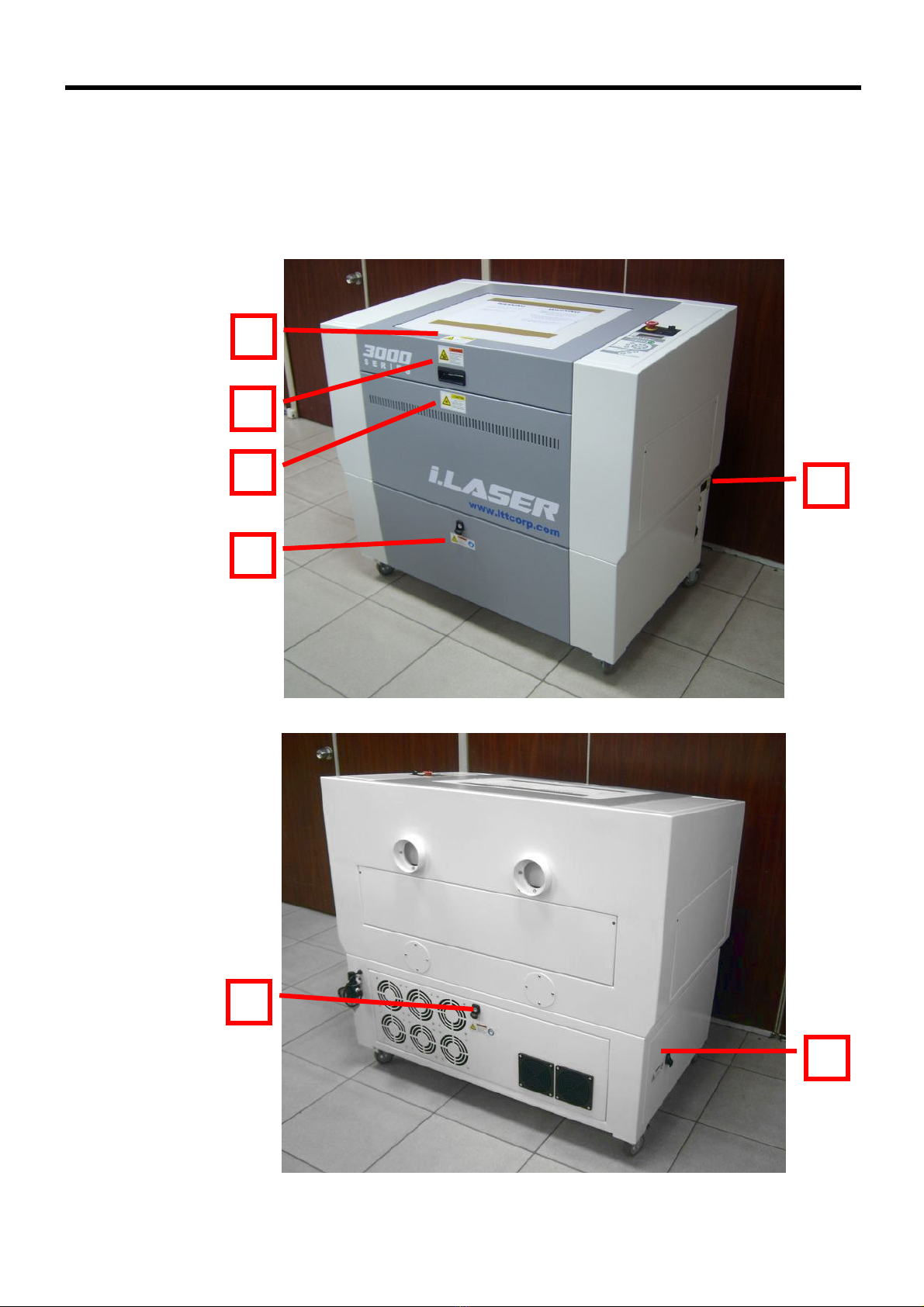
1.2 Name Plate and Warning Labels.....................................................................................6
1.3 Safety Protection Device ...................................................................................................9
Chapter 2 Installation............................................................................. 11
2.1 Unpack and Locate Machine...........................................................................................11
2.2 Package Contents List.......................................................................................................16
2.3 Part Names and Functions ..............................................................................................17
2.4 Hardware nstallation........................................................................................................23
2.5 Driver nstallation...............................................................................................................25
2.5.1 nstall Driver.............................................................................................................25
2.5.2 Uninstall Driver........................................................................................................33
2.5.3 Change USB Cable to Another Port .................................................................35
2.6 CorelDRAW Setup...............................................................................................................37
2.7 AutoCad Setup.....................................................................................................................39
2.8 LTT Product Tools................................................................................................................47
2.8.1 nstall Procedure.....................................................................................................47
2.8.2 Uninstall Procedure................................................................................................51
Chapter 3 Operation ............................................................................... 53
3.1 Operator Position ................................................................................................................53
3.2 Basic Operation Flow.........................................................................................................54
3.3 Machine Operation .............................................................................................................55
3.3.1 Control Panel ............................................................................................................55
3.3.2 Operating Menu.......................................................................................................58
3.4 Print Driver Operation.......................................................................................................65
3.4.1 Laser Tab....................................................................................................................65
3.4.2 Job Tab .......................................................................................................................72
3.4.3 Page Tab.....................................................................................................................75
3.4.4 Power Scale...............................................................................................................78
3.5 LTT Product Tools ................................................................................................................79
3.5.1 System Upgrade......................................................................................................79
3.5.2 Ethernet Settings Upgrade .................................................................................81
Chapter 4 Maintenance ........................................................................... 83
4.1 Daily Cleaning......................................................................................................................83

3
4.2 Weekly Cleaning..................................................................................................................86
Chapter 5 Trouble Shooting .................................................................... 88
Appendices............................................................................................... 89
Appendix 1 Specifications .......................................................................................................89
Appendix 2 Dimensions............................................................................................................90
Appendix 3 Suggested Power and Speed Settings........................................................92

Chapter 1 Safety
4
Chapter 1 Safety
1.1 Safety Regulation
The i.LASER series uses a CO2 Laser as a light source. t is classified as a class-
R
product by CDRH (the Center for Devices and Radiological Health).
Wavelength : 10.6µm
Maximum output po er : 30 ~ 100W
Visibility : Invisible
When operating the i.LASER series, be sure to al ays
comply
ith the safety regulations as follo ing:
Do not attempt to modify or disassemble any component of the machine without
LTT technical support.
Do not open the doors of chassis and access the laser tube
or electronic
components, especially while the machine power is on.
Connect the machine to a grounded outlet. Verify that the voltage of the outlet
is correct for the machine.
Do not disable the interlocks which are on top and front doors.
Be careful about the path of the invisible laser beam shown in figure.
Otherwise,
eye or skin injury may result.

Chapter 1 Safety
5
Do not watch the laser beam directly during operation. Bright light
caused by
the lasing process can damage the eye.
The side and rear doors are fixed by screws for safety. f you open these doors,
the i.LASER will become a Class 4 laser device
. For your safe, please wear
protective goggles.
The laser beam may cause fire. Never leave machine
along without other
operator watching during the laser cutting and engraving process.
Keep a fire
extinguisher near the machine at all times.
Blowing materials with air flow from nozzle while cutting or engraving can avoid
fire occurring and also obtain good quality.
Verify that materials used in the engraver are proper for lasing. Never engrave
or cut substrates that contain PVC or Teflon.
Good efficiency of exhaust system makes you avoid breathing dust, debris
or
poison gas.
Please comply with maintenance schedule as chapter 4 to keep i.LASER
working
well.
Before you execute auto focusing function, please make sure that there will be
no crashing between motion system and other objects. For safety, it is NOT
recommended to use auto focusing function on inequality materials.

Chapter 1 Safety
6
1.2 Name Plate and Warning Labels
The labels as following are affixed to the i.LASER
. These labels must never be
removed. f they are damaged or tampered for any reason, please request for LTT
immediately to replace them.
1
4
2
2
3
4
2

Chapter 1 Safety
7
1
2
La s e r Too l s & Te c hn i c s C o r po r ati o n
Model No: i.LASER 3000
Serial No: 810000
Specification: V30, 110~220V, 10A
Manufacture Date: 2008 .12
N o . 1 2 1 , L a n e 9 9 , P U - D I N G R O A D ,
H S I N C H U C I T Y, TA I W AN , R . O . C .
TE L : 8 8 6 - 3 - 5 7 2 7 7 7 2
FA X : 8 8 6 - 3 - 5 7 2 8 8 9 8
5

Chapter 1 Safety
8
3
4
5

Chapter 1 Safety
9
1.3 Safety Protection Device
Interlock
The laser beam will not be emitted if you open the top or front
doors. When any door
is opened, the LED indicator of “DOOR” on control panel will be off.
Both doors close
Any door opens
Laser S itch
Laser switch on control panel can shut down the power of laser system immediately
,
and it has no effect on motion system. Compared with interlock, Turning off l
aser
switch can save power. When you turn on laser switch, the LED indicator of “LASER”
on control panel will be on (it needs to take more than 5 seconds to warm up laser
tube while you turn it on).
ON
OFF

Chapter 1 Safety
10
Emergency Stop S itch
Pressing the red pushbutton can shut down t
he main power of system immediately
when emergency condition occurs. And turning right the red pushbutton
can recover
the power (Before recovering power, please clear the trouble in the machine fisrt).
ON
OFF

Chapter 2 Installation
11
Chapter 2 Installation
2.1 Unpack and Locate Machine
This section explains how to unpack and locate machine.
1. Remote the strings.
2. Remove the protective bag.

Chapter 2 Installation
12
3. Remove the upper box. (If you order slide board.)
4. Remove the top cover.

Chapter 2 Installation
13
5. Remove the side cover and foam.
6. Remove the protective bag.

Chapter 2 Installation
14
7. Remove the foam at bottom.
8. Place the slide board hich is
in the upper box and roll do n
the machine. (If you order slide board.)

Chapter 2 Installation
15
9. Locate the machine and keep the recommended spa
ce for
maintenance.
Unit: mm
10. Lock the heels to locate the machine.

Chapter 2 Installation
16
2.2 Package Contents List
This section explains the package contents of the i.LASER. The
packages include the
following components. Before using the u
nit, check that all components have been
included in the packages.
1 Box 5 LaserCAM Driver CD-Rom
2 Cotton S ab 6 USB Cable Driver CD-Rom
3 Alcohol Dropper 7 USB Cable
4 Allen Wrench 8 Po er Cable
8
7
6
4
3
2
1
5

Chapter 2 Installation
17
2.3 Part Names and Functions
This section explains the main part names and functions of the i.LASER.
1. Lid
This lid has interlock sensors for safety. f you open this door, the laser will be not
emitted.
2. Front Door
This door has interlock sensors for safety. f you open this door, the laser will be not
emitted.
3. Side Door (Right)
You can work on long materials through two side doors. These door
s have no
interlock sensors, so they are locked by screws for safety. f you open these doors
,
the system becomes a Class 4 laser device.
4. Front Door of Chassis
Mostly opening this door is for maintaining. Do NOT open this door if it’
s not
necessary, especially the machine power is on.
1
2
4
3

Chapter 2 Installation
18
5. Exhaust Port
These two ports can exhaust the smoke which is caused by cutting or engraving.
These ports have to be connected to blower through pipes
6. Rear Door
You can work on long materials th
rough front door and this door. This door also has
no interlock sensors, so it is locked by screws for safety.
f you open this door, the
system becomes a Class 4 laser device.
7. Air Filter
This part provides air assist through the hose which is connected to air compressor.
8. Fans
These parts can dissipate the heat in the chassis which is caused by laser generator.
9. Rear Door of Chassis
Mostly opening this door is for maintaining. Do NOT open this door if it’
s not
necessary, especially the machine power is on.
10. Side Door (Left)
You can work on long materials through two side
doors. These doors have no
interlock sensors, so they are locked by screws for safety. f you open these doors
,
the system becomes a Class 4 laser device.
11. Side Door of Chassis
Mostly opening this door is for maintaining. Do NOT open this door if it’
s not
necessary, especially the machine power is on.
6
7
10
11
5
8

Chapter 2 Installation
19
12. Windo Lens
This part can protect 1st ~3rd mirror against dusts or debris
. t should be cleaned this
lens daily. (See chapter 4)
13. 4th Mirror
This part reflects laser beam to carriage.
Also, it should be cleaned this lens daily.
(See chapter 4)
14. Table
This part can carry materials for cutting and engraving. Y
ou can move it up and down
by the keys on control panel. (See section 3.2.1)
15. Carriage
This part includes 5th mirror, focal lens, nozzle, and auto focus set. Y
ou can move it
left, right, forth and back by the keys on control panel. (See section 3.2.1)
15
14
13
12
Table of contents