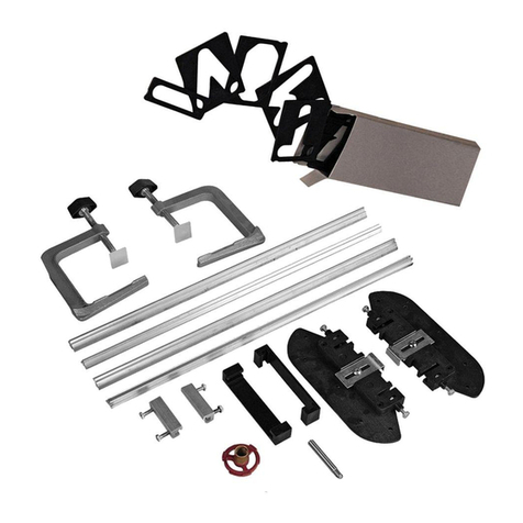
Niedax W-ALS 50X35 User manual

BA W-ALS 50X35_50X55 01/20 GB
MANUAL
Notching tools
• W-ALS 50X35
• W-ALS 50X55
for surface metal
Drive (basic unit) not included
Distributed by:
Niedax GmbH & Co. KG
Asbacher Straße 141
D-53545 Linz / Rhein
Tel.: +49 (0) 2644/5606-0
Fax: +49 (0) 2644/5606-13
www.niedax.de

BA W-ALS 50X35_50X55 01/20 GB
TABLE OF CONTENTS
Package contents Seite 1
Work safety Seite 1
Intended use Seite 2
Technical data Seite 2
Safety instructions Seite 3
Description of components Seite 4
Assembly onto the drive / basic unit Seite 4
Operation Seite 5
Disassembly Seite 7
Maintenance and cleaning Seite 8
Notes regarding the notch Seite 8
Niedax GmbH & Co. KG - Asbacher Straße 141 - D-53545 Linz/Rhein

BA W-ALS 50X35_50X55 01/20 GB
Niedax GmbH & Co. KG - Asbacher Straße 141 - D-53545 Linz/Rhein
PACKAGE CONTENTS
WORK SAFETY
• NotchingtoolW-ALS50X35orW-ALS50X55(seegurebelow)
• Toolbox(withoutgure)
• Manual(withoutgure)
Before starting to work, the relevant safety regulations and accident prevention regulations
are to be noted.
The operator absolutely needs to wear work gloves and safety goggles.
The operation of the complete unit is carried out solely by a single and trained expert.
1/8

BA W-ALS 50X35_50X55 01/20 GB
INTENDED USE
Niedax GmbH & Co. KG - Asbacher Straße 141 - D-53545 Linz/Rhein
The notching tool is to be used exclusively to notch (punch) the side walls (Figure 01.1,
Figure 01.2) of a surface metal raceway (LLK …/LUK …) as well as the industrial surface
metal raceway (LUE …/LI …) by the Niedax GmbH & Co. KG, made out of steel or stainless
steel.
• NotchingtoolW-ALS 50X35 (Figure 01.1) allows a notch of 50 x 35 mm;
Of a surface metal raceway (LLK …/LUK …) with a height of 40 mm
(Length of the notch: 50 mm; height -: 35 mm)
• NotchingtoolW-ALS 50X55 (Figure 01.2) allows a notch of 50 x 55 mm;
Of a surface metal raceway (LLK …/LUK …) and the industrial surface metal raceway
(LUE …/LI …) from a height of 60 mm
(Length of the notch: 50 mm; height -: 55 mm)
Larger notches, by moving the tool back or forth, are at any time possible. For this purpose
an additional hydraulic drive (basic unit) is required. The hand hydraulic W-HHA 360-3 can be
ordered from Niedax GmbH & Co. KG and can be used together with the notching tool.
2/8
TECHNICAL DATA
Model no. W-ALS 50X35 W-ALS 50X55
Dimensions tool
(Length x Width x Depth) 162 x 72 x 80 mm 162 x 72 x 100 mm
Dimensions of notch
(Length x Height) 50 x 35 mm 50 x 55 mm
Weight of tool 2,4 kg 2,7 kg
Connection thread UNF 19
required punching force of basic unit (hy-
draulic) 65 to 85 kN
Required stroke of basic unit 19 to 23 mm
Toolbox dimensions
(Length x Width x Depth) 230 x 275 x 83 mm
Toolbox weight 0,7 kg
Figure 01.2Figure 01.1

BA W-ALS 50X35_50X55 01/20 GB
• Thenotchingtoolisonlyallowedtobeusedandoperatedbyasinglepersonwithsucient
professional knowledge (specialist).
• Theoperatorhasreadthismanualaswellasthemanualforthedrive/basicunitofthecor-
responding manufacturer and understood their content.
• Beforeoperatingthenotchingtool(punchingtool)theoperatorhastobe
instructed in its use.
• Theoperatorrespectstherelevantguidelinesandsafetyregulations.
• Theoperatorchecksthenotchingtoolbeforethepunchingprocessforwearanddamages.
• Thenotchingtoolisnottobeusedincaseanydamagesorirregularitiesarenoticed.
• Theoperatorpaysattentiontouseaclean,evenandsolidsurfaceforthesurfacemetal
raceway in the planned punching process.
• Thecoverofthesurfacemetalracewayisremovedandnoforeignbodiesetc.andcables
are located in the area of the notching tool.
• Bothhandsoftheoperatorareinthepunchingprocessatthedesignated
places on the drive / basic unit (see section 9: Operation)
• Theoperatorhastovisuallyobservethepunchingprocess.
• CAUTION: Risk of crushing or cutting in the area of the notching tool.
• Incasethenotchingtoolgetstiltedand/orjammedinthepunchingprocess,the battery has
to be removed from the drive and the entire tool has to be competently removed from the
surface metal raceway.
• Theoperatorwearsthepersonalprotectiveequipment(workgloves,workshoes,safety
goggles etc.).
• Theoperatingcompanyensuresallofthemeasuresaboveandmonitorstheircompliance.
Niedax GmbH & Co. KG - Asbacher Straße 141 - D-53545 Linz/Rhein
SAFETY INSTRUCTIONS
3/8

BA W-ALS 50X35_50X55 01/20 GB
DESCRIPTION OF COMPONENTS
ASSEMBLY ONTO THE DRIVE / BASIC UNIT
Niedax GmbH & Co. KG - Asbacher Straße 141 - D-53545 Linz/Rhein
The completely assembled unit primarily consists of 2 parts (Figure 02):
1. Drive / basic unit (Manufacturer for example Klauke, Makita, Alfra, Milwaukee, Cimco etc.).
For the drive / basic unit, observe the operating instructions of the manufacturer or sup-
plier. As an alternative to the illustrated hydraulic punch, the hydraulic tool W-HHA 360-3
(operated manually) by the Niedax GmbH & Co. KG can be ordered and used.
2. Notchingtool(W-ALS50X35;W-ALS50X55);exclusivelyusabletonotchthesidewalls
of a surface metal raceway as well as the industrial surface metal raceway by the Niedax
GmbH & Co. KG.
• Thebatteryhastoberemovedbefore,whileassemblingthenotchingtoolwiththedrive/
basic unit.
• Thethreadbolt(2.1,thread:UNF19)ofthenotchingtoolisscrewedintothestopinthe
head of the basic unit (1.1).
• Afterwardsthechargedbatteryisinsertedintothebatteryholder(1.2)ofthebasicunit.
Now the complete unit is ready for operation.
4/8
1.2 Battery holder
(battery is removed)
2. Notching tool
2.1 Thread bolt
1. Basic unit
1.1 Head of the basic unit
Figure 02

BA W-ALS 50X35_50X55 01/20 GB
Niedax GmbH & Co. KG - Asbacher Straße 141 - D-53545 Linz/Rhein
OPERATION
Firstly the positions of the notches are marked on the side walls of the surface metal raceway.
The notch, produced by the complete unit, has a height of 35 mm respectively 55 mm and
a length of 50 mm. The cover of the surface metal raceway is removed and no cables and
foreignobjectsetc.arelocatedintheareaofthenotchingtool.
The nut (2.2) of the notching tool has to be fully loosened to open the notching tool. The mo-
vable punch (2.3) is thereby the furthest from the mould (2.4). Now the notching tool can be
inserted over the side wall into the surface metal raceway.Afterwards the nut (2.2) has to be
manually tightened up to the stop in order to minimalize the distance between the punch (2.3)
andthemould(2.4)andinordertocreateatighttbetweenthenotchingtoolandtheside
wall of the surface metal raceway (see Figure 04 and 05).
Is the required notch at the end of the surface metal raceway, the entire tool can be inserted
from the side (lengthwise) as well.
In any case, attention must be paid to tighten the nut (2.2) up to the stop in order to minimali-
ze the distance between the punch (2.3) and the mould (2.4) before operating the tool.
5/8
2.2 Nut
2.3 Punch 2.4 Mould
1.5 Reset lever
1.3 Battery
1.6 Handle
1.4 Operating Switch
2. Notching tool 1. Basic unit (hydraulic punch)
1.1 Head of the basic unit
Figure 03

WARNING:
Risk of cutting
(possibleejectionofmetal
sheet)
WARNING:
Risk of crushing
(punch moves towards mould)
BA W-ALS 50X35_50X55 01/20 GB
WARNING(seegure06)
Niedax GmbH & Co. KG - Asbacher Straße 141 - D-53545 Linz/Rhein
• Risk of crushing exists between the punch and the mould of the notching tool.
• Risk of cutting exists at the cut. Depending on the material of the cut metal sheet, it is
possible,thatthecutsheetsectiongetsejectedinthedirectionofthedrive/basicunit.
One hand grips the blank head (1.1) of the basic unit while the other grips the handle (1.6)
includingtheoperatingswitch(1.4)ofthebasicunit(seegure06).
The notching tool has to be held vertically to the side wall of the surface metal raceway in
ordertoinsureacleanandverticalcutofthesidewallandtoeliminatetheriskofjamming
thenotchingtool.Theredhydraulictankpointstotheoor.Thepunchingprocesshastobe
visually observed by the operator.
6/8
Figure 06
Figure 04 Figure 05

BA W-ALS 50X35_50X55 01/20 GB
Niedax GmbH & Co. KG - Asbacher Straße 141 - D-53545 Linz/Rhein
DISASSEMBLY (SEE FIGURE 02, 03)
Now the punching process can be started by pressing the operating switch (1.4). The opera-
ting switch has to be pressed until a clear crunch from the metal sheet, signifying the comple-
te cut, can be heard and the loose metal sheet section can be seen.
The „drive on block” of the punch on the mould is to be avoided!
Afterwards the reset lever (1.5) of the basic unit is pressed and the notching tool opens (the
punch separates from the mould).
In case the basic unit has reached the end position beforehand, it is now required to press
theresetlevermorermly.
The entire tool is now either removed from the surface metal raceway by lifting it up or moved
sideways for punching further notches.
It is not permitted to punch more than 40 notches in a row due to the risk of overheating the
hydraulic punch.
Forthenextuseonadierentsurfacemetalracewaythenut(2.2)hastobefullyloosenedto
open the notching tool and tightened again after putting the notching tool in position.
No sheets of metal should remain in the mould of the notching tool. If there are they must be
removed.
• Whendisassemblingthenotchingtoolitisabsolutelynecessarytoremove the battery
(1.3) of the drive / basic unit.
• Afterwardsthenotchingtoolcanbeunscrewedfromthebasicunitviathethreadedbolt
(2.1).
• Theinnergearofthebasicunitdoesn’thaveaself-lockingcapacity.
• Becauseofthisitispossibleforthegearofthebasicunittoturnwiththemotionof
unscrewing the notching tool and making disassembly impossible.
• Inthiscasethebatteryhastobeinsertedagain.
• CAUTION: Risk of injury, keep hands out of the area of the notching tool!
• Thentheoperatingswitch(1.4)isactivateduntiltheendpositionisreached.Afterwardsthe
battery is removed. Now the gear of the basic unit (1) is blocked and the notching tool (2)
can be unscrewed. Once this is done, the reset lever has to be pushed for the gear to be
loosened again by the hydraulic system.
7/8

BA W-ALS 50X35_50X55 01/20 GB
MAINTENANCE AND CLEANING (SEE FIGURE 02, 03)
NOTES REGARDING THE NOTCH
Niedax GmbH & Co. KG - Asbacher Straße 141 - D-53545 Linz/Rhein
• Thenotchingtoolisunscrewedandisthereforeseparatedfromthedrive/basicunit.
• Aftereveryusethecuttingsurfacehastobechecked,cleanedandpossibleforeign
bodies have to be removed.
• Thecuttingsurfaceisoiledwithappropriatesprayoil.
• Theductsarecheckedandcleanedaswell.
• Thetoolsarepackedintotheprovidedtoolboxandstoredinadryplace.
• Themaintenancereferencesforthedrive/basicunitmustbeobservedandcarriedout.
The surface metal raceway does have sharp edges in the area of the notch due to the pun-
ching process. This can cause damages to the isolation of cables and the cables themselves
CAUTION: Risk of injury, use personal protective equipment!
Thesharpedgesaretoberoundedoandcoveredwithasuitableedgeprotection.
For this purpose the edge protection RKBA 5 of the Niedax GmbH & Co. KG can be ordered
and used.
8/8
This manual suits for next models
1
Table of contents
Popular Cutter manuals by other brands
Matco Tools
Matco Tools MT1875 Operating instructions, warning information, parts breakdown
Urrea
Urrea CC910 User manual and warranty
Alpha tools
Alpha tools MF 1300 Original operating instructions
Maktec
Maktec MT411 instruction manual

Rockwheel
Rockwheel C2 user guide
Omcan
Omcan FP-CN-0185 instruction manual


