ERNITEC BDR-510/2 User manual

Installation Instruction
for BDR-510/2 & BDR-514/2
Digital Camera Stations
3020-00025 / 98.02.19

1Introduction
A Digital Camera Station forms the receiver end of a digital remote control system. A digital
remote control system is used to control camera functions such as pan, tilt, zoom, focus and
iris, light on/off and open/close gates etc..
A digital remote control system has the advantage of long transmission distance and low cable
installation cost due to the fact that a standard 2 x 0.6 mm twisted pair cable may be used for
the control of up to 12 functions.
The Digital Camera Stations BDR-510/2 and BDR-514/2 is designed with special attention to
transmission safety and stability.
The BDR-510/2 and BDR-514/2 camera stations are addressable which means that up to 64
units can be controlled via one twisted pair line.
The BDR-510/2 and BDR-514/2 are delivered as self-contained units with a mains change-over
switch for selection between 230 VAC and 115 VAC mains voltage.
The BDR-510/2 and BDR-514/2 is housed in an IP65 rated ABS-box and can be used in
connection with SYSTEM 500M and SYSTEM 1000M. Besides the BDR-510/2 and BDR-514/2
can be controlled and programmed directly from the keyboards 1500M, 1501M, 1502M and
1503M.
1.1ERNA Format:
The BDR-510/2 and BDR-514/2 are controlled via the ERNA protocol (Ernitec Asynchronious
Serial One-way Camera Control).
With this camera control protocol it is possible to use standard modems between a system and
a camera station (or between two BDR-5XX) if the distance is more than 1200 meter.
The new ERNA protocol can be generated from a PC, which means that camera control can be
made via the PC's RS-232-C port.
The format of this protocol is as follows (Version 2.0, Release 961016):
1.1.1Physical format: Baudrate = 2400
Parity Bit = None
Data Bit = 8
Stop Bit = 1
1.1.2Frame format:
Header Address Command Data 1 Data 2 Checksum
STX 0-255 1-17 0-255 0-255 Sum of previous bytes
02 Hex 255=Broadcast
Installation Manual
Page 23020-00025

1.1.3Commands:
Comman
dFunction Data 1 Description Data 2 Description CS Type
1Relays 0-255 Bit 0 Pan right
1 Pan left
2 Tilt up
3 Tilt down
4 Zoom wide
5 Zoom tele
6 Focus near
7 Focus far
0-255 Bit 0 Iris open
1 Iris close
2 AUX1
3 AUX2
4 AUX3
5 AUX4
6 AUX5
7 AUX6
ALL
2Call preposition 1-128 Prepos number ---- Not used BDR-55X/575
3Start Sequence prepos 0---- Not used 55x/575/ICU
4Text on/off 0---- Not used BDR-55x
5Save prepos 1-128 Prepos number ---- Not used 55x/575/ICU
6Insert prepos in stack 1-128 Prepos number ---- Not used 55x/575/ICU
7Delete prepos from stack 1-128 Prepos number ---- Not used 55x/575/ICU
8Clear seq. stack 0---- Not used 55x/575/ICU
9Show seq. stack 0---- Not used BDR-55x
10 Latch AUX 0-255 Bit 2 AUX1
3 AUX 2
4 AUX 3
5 AUX 4
6 AUX 5
7 AUX 6
Low=Latch
High=No latch
---- Not used BDR-55x
11 Sequence dwelltime 0-255 Seconds ---- Not used 55x/575/ICU
12 Homepos 0-255 Prepos number
0=Disabled 0-255 10*1sec time-out 55x/575/ICU
13 AUX on/ off 1-8 Relay number 0-1 0=Off 1=On 55x/575/ICU
14 PT Speed 0-255 Pan Speed 0-255 Tilt Speed BDR-575/ICU
15 Auto-paning 1Speed 0-255 BDR-575/ICU
2Limits 1/2
3Start 0
16 Camera Set-up 1Mode 0-255 Bit 0 Gain Ctrl. remote.
1 White bal. remote.
2 Contour corr. remote.
3 Shutter speed
remote.
4 Gain auto.
5 White val. auto.
ICU
2Gain control. 0-255 0=low 255=high
3White balance. 0-255 0=Warm 255=Cold
4Contour corr. 0-255 0=Sharp 255=Soft
5Shutter speed 0-255 0=Fast 255=Slow
6Background comp. 0Not used
Installation Manual
3020-00025 Page 3

Comman
dFunction Data 1 Description Data 2 Description CS Type
17 Alarms 1Configuration 0-255 Bit 0 Alarm 1
0=NC 1=NO
1 Alarm 2
0=NC 1=NO
2 Alarm 1 relay
0=Off 1=On
3 Alarm 2
0=Off 1=On
4 Alarm 1 priority
0=Low 1=High
5 Alarm 2
0=Low 1=High
6 Alarm 1
0=Disable 1=Enable
7 ALarm 2
0=Disable
1=Enable
ICU
3Alarm 1 Set-up 0-255 Bit 0-5 Preposition
6 Relay 1
0=Disable 1=Enable
7 Relay 2
0=Disable 1=Enable
2Alarm 2 Set-up 0-255 Bit 0-5 Preposition
6 Relay 1
0=Disable 1=Enable
7 Relay 2
0=Disable 1=Enable
Installation Manual
Page 43020-00025
2Installation
2.1Box Installation
Choose a plain surface to prevent the box from being twisted and thereby becoming leaky
while mounted. When mounted out-door the box should be oriented with the cable glands
pointing downwards. Screws and wall plugs are supplied in the mounting kit. Drilling
dimensions are shown on figure 2.
2.2Mains installation
The BDR-510/2 or BDR-514/2 should be mounted at a suitable location close to the video
camera where mains are available.The BDR-510/2 and the BDR-514/2 can be supplied with
either 115 VAC or 230 VAC mains voltage. The mains voltage is selected by the mains voltage
change-over switch, refer to figure 2.
Warning: Before connecting the unit to the mains outlet make sure that the mains voltage
change-over switch is set for correct mains voltage in order to avoid damage on the
equipment.
Warning: Make sure the equipment is earthed; otherwise the over voltage protection will not
work!
2.3Cable connections
It is of utmost importance that all cable connections are carried out, exactly as described, in
order to avoid malfunction or damage to the camera station or the connected equipment.
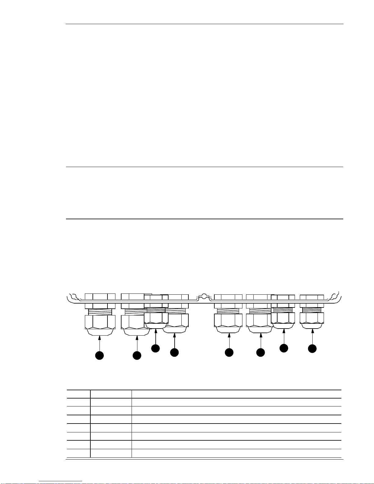
All cables to and from the camera station are fed through the cable glands. Choose an
appropriate size gland for the actual cable and tighten the glands when all cables are
connected. The choice of cable is important to the optimal function of the camera station.
1 2 4 5 6 783
Figure 1, Cable glands lay-out
The following table shows how the cable glands are intended to be used:
No. Size Description
1PG 13.5 Mains input cable
2PG 13.5 Pan/Tilt connection cable
3PG9 Mains output cable
4PG 11 Auxiliary 1 connection cable
5PG 11 Auxiliary 2 connection cable
6PG 11 Zoom lens control cable
7PG 9 ERNA input cable
Installation Manual
3020-00025 Page 5

8PG 9 ERNA output cable
LL The BDR-510/2 - BDR-514/2 Digital Camera Stations must be used with a 3 wire mains
connection and an earthed power outlet.
All electronic equipment can emit or be sensitive to induced electromagnetic noise, which can
be conducted by the connected wires or transmitted as electromagnetic fields.
Electromagnetic noise can cause malfunction or damage to the equipment.
The Series BDR-510/2 - BDR-514/2 are tested and fulfils the following EMC standards:
EN 50081-1 (Emmision)
EN 50130-4 (Immunity)
These standards covers equipment placed in an industrial environment.
The Series BDR-510/2 - BDR-514/2 fulfils the following safety standard:
EN 60950
Installation Manual
Page 63020-00025

2.4BDR-510/2 - BDR-514/2 Layout
The BDR-510/2 and BDR-514/2 have been designed for easy installation and set-up. Figure 2
shows the layout of the camera stations.
130 mm
228 mmDrilling dimensions:
B1
C1C2
C3
C4 C5
C6
C7
C8
C9
C10
C11
C12
C13 C14
C15
C16
C17
D1
D2
D3
D4
D5
F1
K1
K2
K3
K4
K5 K6K7K8K9K10
K11
K12
K13
L1
L2
L3
L4
N1
N2
N3
N4
N5
RC1
RC2
RC3
RC4
RC5
RC6
RS1
R1
R2
R3
R4
R5
R6
R7
R11
R12
R13
SW1
S1
6V
12V
230
115 S2
TP1
TP2 TP3
TP4 TP5
12 11 10987
654321
TR1
V1
SYNC
V2
ERROR
V3 V4
V5
V6
V7
V8
V9
V10
POWER
ON
V11
V12
V13
V14
Y1
Y2
Y3
Y4
Y5
Y6
Y7
Y8
Y9
Y10
Y11
Y12
Y13
Y14
Y15
Y16
Y17
Y18
Y19
Y20
MAINS
CTRL
0498-00026
rev.: 0,1
ernitec
ACHTUNG
DANGER
ACHTUNG
DANGER
X1 X2 X3 X4 X5 X6 X7
SELECT
OUTIN
LENS ICIOFFFNZTZW
AUX2AUX1
P/T TDTUPRPLLPE
MAINSIN MAINSOUT
PE LNLNA AB B
1 2 3 5 6
7
9
8
4
1011
12
13
Figure 2, BDR-510/2-BDR-514/2 Layout
Description
No. BDR-510/2 BDR-514/2
1Mains input
2Mains output
3Pan/Tilt connection Auxiliary connection AUX 3-6 (4)
4Auxiliary connection AUX 1 & 2 (2)
5Lens connection
6ERNA Camera control input/output
7ERNA error detection
8ERNA sync. detection
9Address switch
10 6 or 12VDC lens voltage selection
11 Power on indication
12 Fuse for Pan/Tilt Fuse for AUX 3-6
13 Mains voltage change-over switch 115/230 VAC
Installation Manual
3020-00025 Page 7
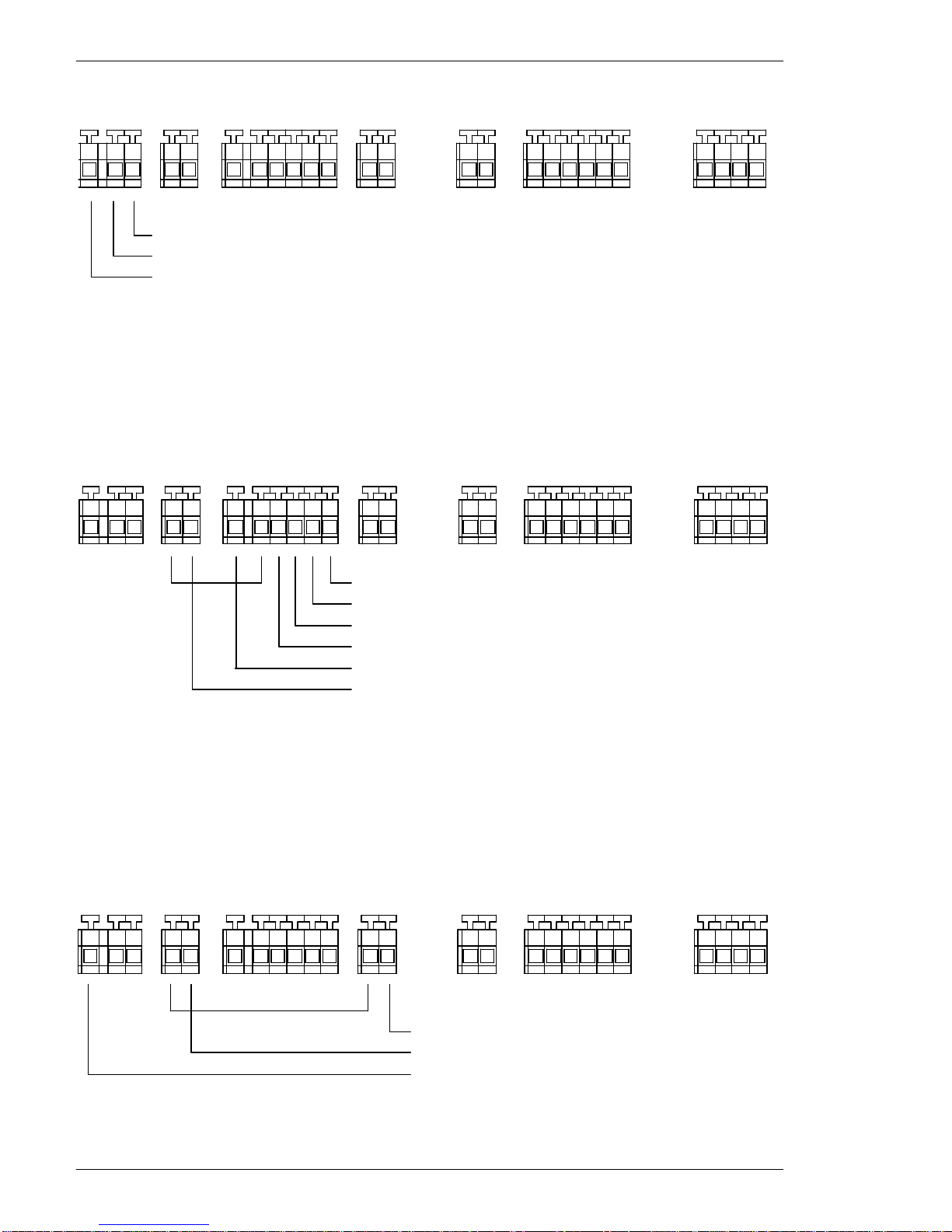
2.4.1Mains connection
Connect the mains lead to the terminal block X1. Refer to figure 3.
X6 X7
OUTIN
LENS ICIOFFFNZTZW
CTRL
X1 X2 X3 X4 X5
AUX 2
AUX 1
P/T TDTUPRPLLPE
MAINS IN MAINS OUT
PE LNLNAA
BB
Mains LIVE
Mains NEUTRAL
Mains EARTH
+ +- -
Figure 3, Mains connection
Make sure that each terminal is connected to the corresponding terminal of the mains outlet
(i.e. Phase to Phase, Neutral to Neutral and Ground to Ground). Otherwise malfunction or even
damage to the camera station will occur.
For specification of mains, refer to Specifications
2.4.2Pan/Tilt connection (Only BDR-510/2)
A high voltage Pan/Tilt is connected to the terminal blocks X2, and X3. Refer to figure 4.
X1 X2 X3 X4 X5 X6 X7
OUTIN
LENS ICIOFFFNZTZW
AUX 2AUX 1
TDTUPRPLLPE
MAINS IN MAINS OUT
PE LNLNA A
BB
CTRL
P/T Tilt Down (4)
Pan Right (2)
Pan left (1)
EARTH(7)
NEUTRAL (6)
Tilt Up (3)
+ +
- -
Figure 4, Pan/Tilt connection
The numbers in () indicates the pin number of the MPT-1/10 Pan/Tilt. For further information,
refer to the Pan/Tilt installation instruction.
When using high voltage Pan/Tilt always connect the GROUND or EARTH wire.
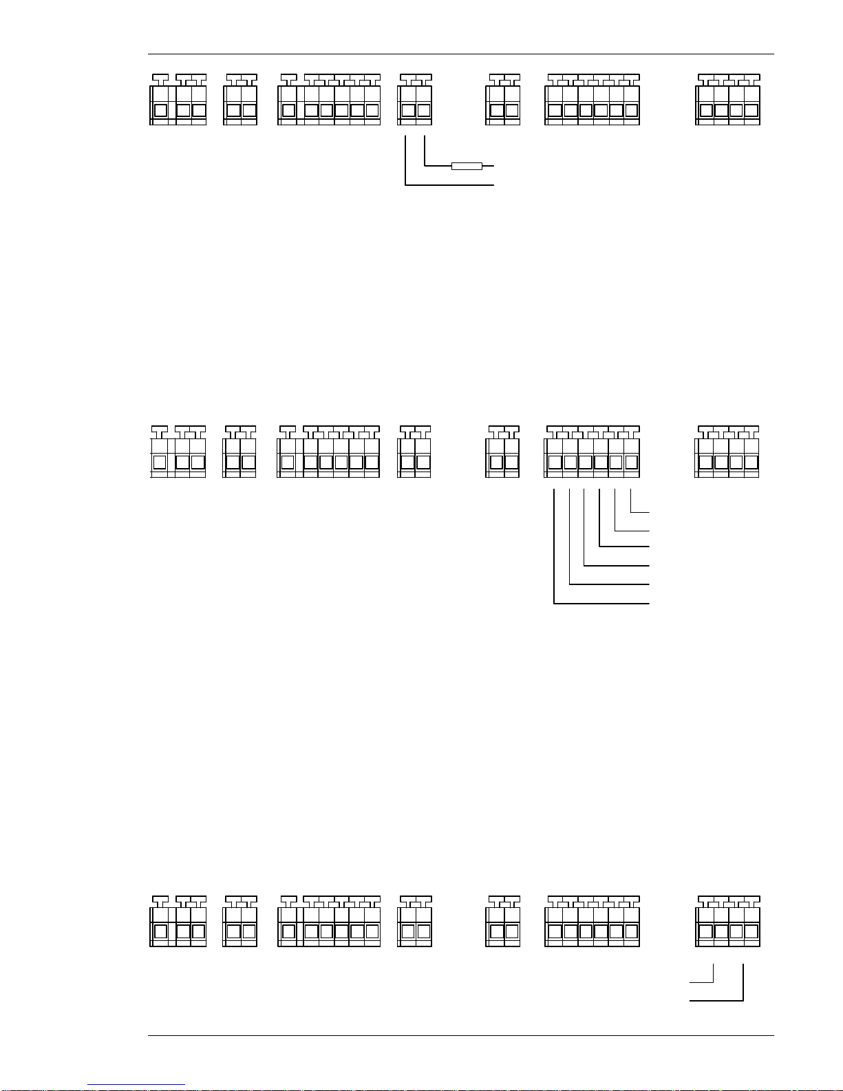
2.4.3Auxiliary connection
The auxiliary functions connected to terminal X4 and X5, allows control of mains supplied
equipment or equipment supplied with an external voltage, like 24 VDC etc. refer to
Specifications for maximum load of the relay contacts.
X1 X2 X3 X4 X5 X6 X7
OUTIN
LENS ICIOFFFNZTZW
AUX 2AUX 1
P/T TDTUPRPLLPE
MAINS IN MAINS OUT
PE LNLNA AB B
CTRL
LIVE
NEUTRAL
EARTH
+ +
--
Figure 5, Connection of Mains supplied Auxiliary Equipment
Installation Manual
Page 83020-00025
X1 X2 X3 X4 X5 X6 X7
OUTIN
LENS ICIOFFFNZTZW
AUX 2AUX 1
P/T TDTUPRPLLPE
MAINS IN MAINS OUT
PE LNLNA A
BB
CTRL
LOAD External
Voltage
+ +
- -
Figure 6, Connection of external supplied Auxiliary Equipment
Be careful not to exceed the maximum rating of the relays, refer to Specifications for maximum
load of the relay contacts.
2.4.4Auxiliary connection AUX 3-6 (Only BDR-914/2)
The pan/tilt relays are used as auxiliary relay contacts, having the L P/T terminal located at X3 as
a common point. The PL relay is activated by the AUX 3 function, PR by AUX 4, TU by AUX 5
and TD by AUX 6.
2.4.5Motorised Lens connection
The Motorised lens is connected to terminal X6, see figure 7
Iris Close
Focus Far
Focus Near
Zoom Tele
Zoom Wide
Iris Open
X1 X2 X3 X4 X5 X6 X7
OUTIN
LENS ICIOFFFNZTZW
AUX 2
AUX 1
P/T TDTUPRPLLPE
MAINSIN MAINSOUT
PE LNLNA A
BB
CTRL
+ +
- -
Figure 7, Connection of motorised lens
2.4.6ERNA Camera control input connection
The ERNA signal is connected to terminal X7, refer to figure 8.
It is important that the polarity of the connection is correct, otherwise it will not be possible to
get control.
Note, the ERNA input is galvanic separated from the rest of the circuit in order to avoid ground
loop problems.
DO NOT CONNECT THE SCREEN FROM THE CABLE TO THE CAMERA STATION
GROUND.
2.4.7ERNA Camera control output connection
The ERNA output signal is connected to terminal X7, refer to figure 8. In case of power failure
the ERNA signal will be routed to the next camera station via a by-pass relay.
X1 X2 X3 X4 X5 X6 X7
OUTIN
LENS ICIOFFFNZTZW
AUX 2
AUX 1
P/T TDTUPRPLLPE
MAINS IN MAINS OUT
PE LNLNA AB B
CTRL
ERNA output
ERNA input
+ +
- -
Figure 8, ERNA Camera control input and output
Installation Manual
3020-00025 Page 9

3Adjustment and Settings
The BDR-510/2 series has been designed for easy installation and set-up. All settings is made
via switches or jumpers. Figure 9 shows where the different switches and jumpers are located:
C4 C5
C7 C12
D2
D4
D5
R3
R4
TP1
TP4
V3
V5
Y19
B1
C1C2
C3
C8
D1
N4
RS1
R1
R2
R11
R12
R13
S1
6V
12V
TP2 TP3
TP5
V1
SYNC
V2
ERROR
SW1
ON
1 2 3 4 5 6
2 1
Figure 9, Jumper and switch lay-out.
3.1Address settings (1)
With the BDR-510/2 series it is possible to address up to 64 units on one twisted pair line:
Switch SW1
Description 123456
Address number "0" ON ON ON ON ON ON
Address number "1" ON ON ON ON ON OFF
Address number "2" ON ON ON ON OFF ON
Address number "3" ON ON ON ON OFF OFF
Address number "4" ON ON ON OFF ON ON
Address number "5" ON ON ON OFF ON OFF
Address number "6" ON ON ON OFF OFF ON
Address number "7" ON ON ON OFF OFF OFF
Address number "8" ON ON OFF ON ON ON
Address number "9" ON ON OFF ON ON OFF
Address number "10" ON ON OFF ON OFF ON
Address number "11" ON ON OFF ON OFF OFF
Address number "12" ON ON OFF OFF ON ON
Address number "13" ON ON OFF OFF ON OFF
Address number "14" ON ON OFF OFF OFF ON
Address number "15" ON ON OFF OFF OFF OFF
Address number "16" ON OFF ON ON ON ON
Installation Manual
Page 10 3020-00025

Address number "17" ON OFF ON ON ON OFF
Address number "18" ON OFF ON ON OFF ON
Address number "19" ON OFF ON ON OFF OFF
Address number "20" ON OFF ON OFF ON ON
Address number "21" ON OFF ON OFF ON OFF
Address number "22" ON OFF ON OFF OFF ON
Address number "23" ON OFF ON OFF OFF OFF
Address number "24" ON OFF OFF ON ON ON
Address number "25" ON OFF OFF ON ON OFF
Address number "26" ON OFF OFF ON OFF ON
Address number "27" ON OFF OFF ON OFF OFF
Address number "28" ON OFF OFF OFF ON ON
Address number "29" ON OFF OFF OFF ON OFF
Address number "30" ON OFF OFF OFF OFF ON
Address number "31" ON OFF OFF OFF OFF OFF
.....
Address number "62" OFF OFF OFF OFF OFF ON
Address number "63" OFF OFF OFF OFF OFF OFF
3.212 V or 6V Lens voltage (2)
The voltage to the motorised zoom lens can be set with Jumper S1.
Jumper on Pin 1 and 2 = 12 VDC
Jumper on Pin 2 and 3 = 6 VDC
Installation Manual
3020-00025 Page 11

4Specifications
Specifications
Description Parameter Min. Typ Max. Unit Note
Inputs Mains 207 230 253 VAC
104 115 126 VAC
Control (ERNA) 2,5 12 Vpp
Outputs Control (ERNA) 6Vpp
Lens Voltage 6 12 VDC
Lens Current 150 mA per function.
Pan/tilt Voltage 250 VAC
Pan/tilt Current, total consumption 2Atotal, fused.
AUX 1 - AUX 2 voltage 250
24 VAC
VDC
AUX 1 - AUX 2, max. current 5ANOT fused.
General Power consumption, 5VA
Temperature range -15 55 ºC
Relative humidity 95 %
Comply to EN 50081-1
EN 50130-4
EN 60950
EMC
Safety
Enclosure IP 65 ABS box.
Dimensions excl. cable glands 250 x 160 x 90 mm
Weight 1,2 Kg
HEAD OFFICE: ERNITEC A/S, HØRKÆR 24, P.O. BOX 720, DK-2730 HERLEV, DENMARK
TELEPHONE: +45 44 92 30 00, TELEFAX: +45 44 92 72 82
UK OFFICE: ERNITEC UK, GERRARD HOUSE, WORTHING ROAD, EAST PRESTON, WEST SUSSEX BN16 1AW, ENGLAND
TELEPHONE: (01903) 77 27 27, TELEFAX: (01903) 77 27 07
GERMAN OFFICE: ERNITEC GmbH., STORMARNRING 28, 22145 STAPELFELD, GERMANY
TELEPHONE: (040) 675625 0, TELEFAX: (040) 675625 25
FRENCH OFFICE: ERNITEC FRANCE, PARC PEREIRE, 95 RUE PEREIRE, BAT. D, 78100 SAINT GERMAINE EN LAYE, FRANCE
TELEPHONE: (1) 39 21 12 00, TELEFAX: (1) 39 21 12 95
Installation Manual
Page 12 3020-00025

JAPAN OFFICE: ERNITEC JAPAN LTD., 8-16 GAKUEN-HIGASHIMACHI, 1-CHOME, KODAIRA-SHI, TOKYO 187, JAPAN
TELEPHONE: (0)423 466290, TELEFAX: (0)423 465646
Installation Manual
3020-00025 Page 13
This manual suits for next models
1
Table of contents
Other ERNITEC Receiver manuals


