Improper operation can cause serious
injury or death.
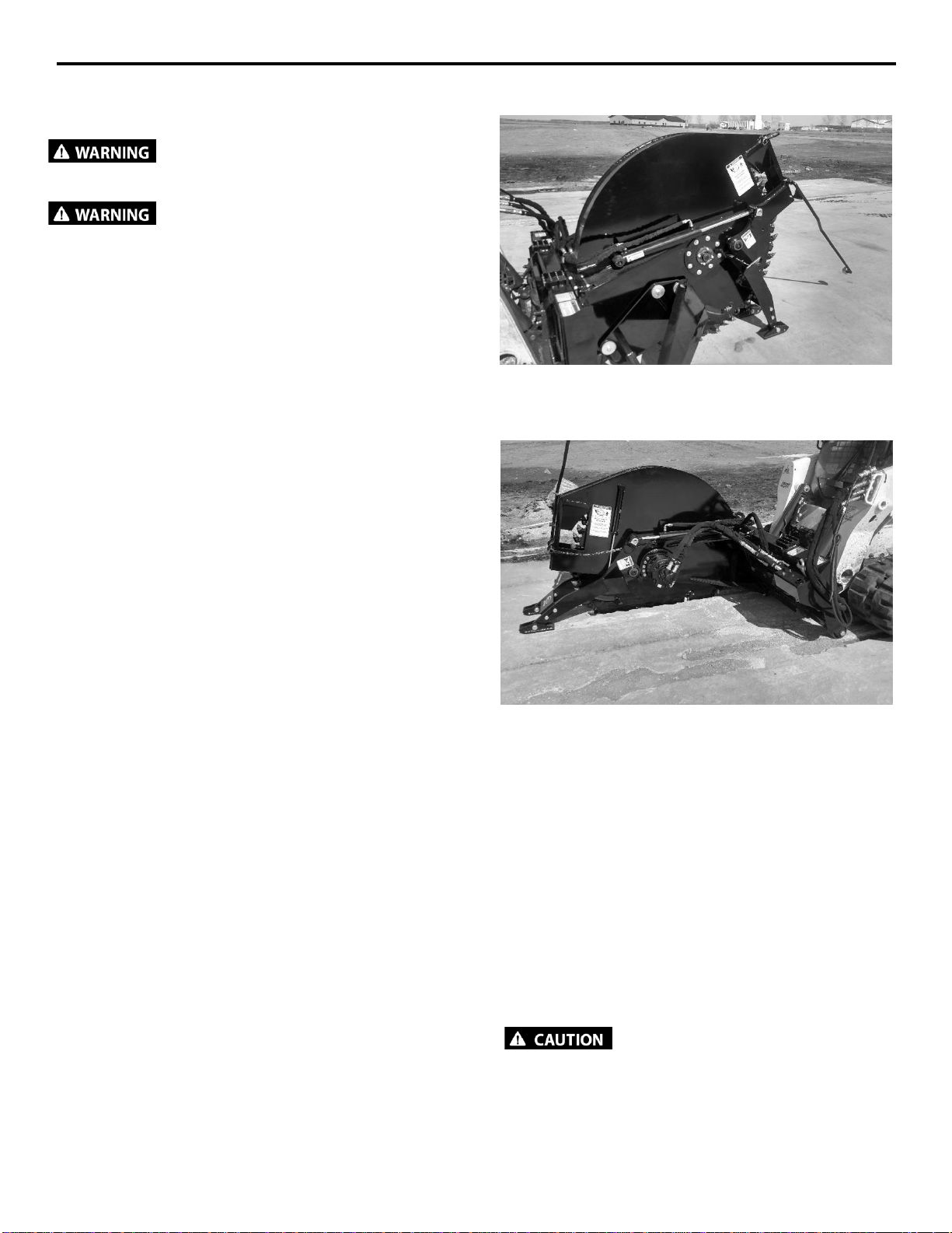
Pre-operation
This attachment is designed for trenching through
cement, asphalt, and rocky soil conditions.
NEVER use this machine for any other purpose.
Read the operators manual for the “Skid Steer
Loader.”NEVER allowuntrained peopleto operate.
Operating instructions must be given to everyone
before operating this attachment and at least once
a year thereafter in accordance with OSHA
regulations.
NEVER exceed the maximum recommended input
power or speed specifications for the attachment.
Over-powering or over-speeding the attachment
may cause personal injury and/or machine
damage.
Keep all shields, guards, and covers in place.
Do not modify equipment or add attachments that
are not approved by Erskine Attachments LLC.
Use adequate safety warning lights and devices as
required by local regulations. Obey all local laws
and regulations regarding machine operation on
public property. Always call before you dig (1-888-
258-0808). When you call, you will be directed to a
location in your state/city for information about
buried lines (electric, telephone, cable TV, water,
sewer, gas, etc.).
Operation
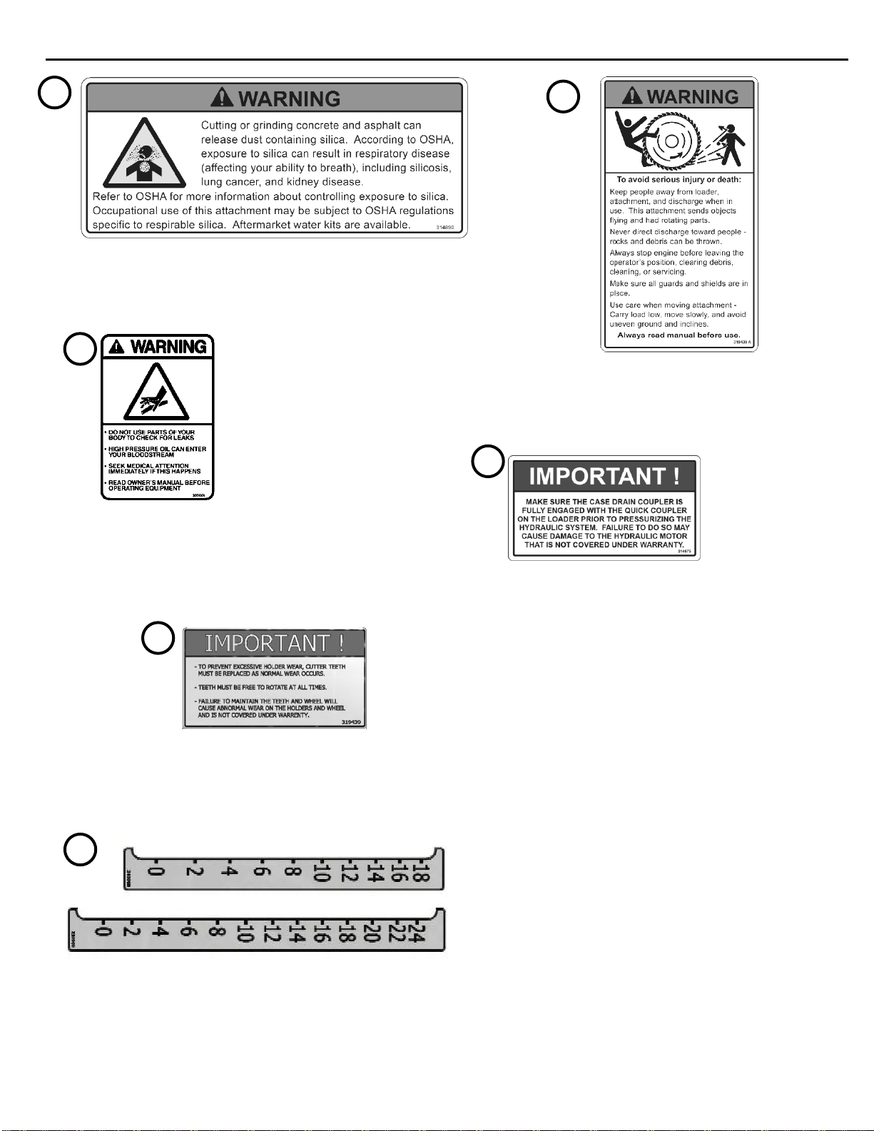
Milling concrete and asphalt can release dust
containing silica. According to OSHA, exposure to
silica can result in respiratory diseases (affecting
your ability to breath), including silicosis, lung
cancer, and kidney disease. Refer to OSHA for
more information about controlling exposure to
silica. Occupational use of this attachment may be
subject to OSHA regulations specific to respirable
silica.
To protect the operator from hearing loss, ear
protection is required unless the loader is equipped
with a noise reduction cab that meets OSHA
1910.95 standard.
Operation (continued)
Keep people away from loader, attachment and
discharge when in use. This attachment sends
objects flying and has rotating parts.
NEVER operate near embankments or terrain that is
so steep that rollover could occur.
Always stay in the operator position when using the
attachment.
Before leaving the operators position, disengage
hydraulic drive, lower the attachment to rest flat on
the ground, stop engine, set park brake, and wait for
all motion to stop.
NEVER place head, hands, feet, or objects in the
discharge area or clear debris while engine is
running.
lines.
result.
operation.