ES ENIP-2-X1 Series User manual

Multifunctional measuring transducer
ENIP-2
Manual
ENIP.411187.002. Rev. 11.2020

Table of contents
ENIP-2, manual, ENIP.411187.002. Rev. 11.2020 2
Table of contents
Introduction ................................................................................................ 4
Glossary and symbols .................................................................................... 5
1General information ................................................................................. 6
2Design, dimensions, naming convention ........................................................ 8
2.1 ENIP-2-…-X1 (Standard)...................................................................... 8
2.2 ENIP-2-…-32 (Compact) .....................................................................12
3Features ........................................................................................... 15
3.1 General information ........................................................................15
3.2 Measured parameters .......................................................................16
3.3 Digital signals ................................................................................19
3.4 Analog outputs ...............................................................................21
3.5 Interfaces and protocols....................................................................21
3.6 Extension display panel.....................................................................25
3.7 Real-time clock ..............................................................................27
3.8 Event logging.................................................................................27
4Specification ...................................................................................... 29
4.1 Measuring input ..............................................................................29
4.2 Operating conditions........................................................................29
4.3 Accuracy ......................................................................................30
4.4 Power supply .................................................................................31
4.5 Isolation.......................................................................................32
5Operation........................................................................................... 33
5.1 Package contents ............................................................................33
5.2 Before installation............................................................................33
5.3 Mounting ......................................................................................34
5.4 Connection ...................................................................................35
6Configuration settings............................................................................. 38
6.1 Firmware update ............................................................................38
6.2 «ES Configurator»software..................................................................39
6.3 ENIP-2 web-interface ........................................................................49
6.4 Reset to default settings ...................................................................50
7Maintenance........................................................................................ 51
8Transportation, packing and storage............................................................. 52
9Self-diagnostics of ENIP-2 ........................................................................ 53
Appendix A1. Wiring diagrams of ENIP-2 Standard and PMU ....................................... 54
Appendix А2. Wiring diagrams of ENIP-2 Compact................................................... 57
Appendix A3. Wiring diagrams for extension devices ................................................ 60
Appendix B. ENIP-2: Modbus............................................................................ 66

Table of contents
ENIP-2, manual, ENIP.411187.002. Rev. 11.2020 3
Appendix C. ENIP-2: IEC 60870-5-101 and IEC 60870-5-104 ....................................... 73
Appendix D. ENIP-2: IEC 61850......................................................................... 86
Appendix E. ENIP-2: SNMP .............................................................................. 93

Introduction
ENIP-2, manual, ENIP.411187.002. Rev. 11.2020 4
Introduction
The Manual contains information about functions, recommendations for use, technical
support, maintenance, packing, transportation, storage, as well as wiring diagrams to
electrical grid, digital interfaces, digital I/O.
Read this manual carefully before using the device.
Typical users
Engineers, personnel involved in setting, operation and maintenance of the devices.
Validity range
This manual applies to all ENIP-2 modifications.
Support
If you have any questions about the device, please, do not hesitate to contact technical
support of «Engineering center “Energoservice”:
Website:
www.enip2.com
Phone:
+7 (8182) 65-75-65
E-mail:
ATTENTION:
When using ENIP-2, follow the rules and information set in this manual;
Only qualified personnel are supposed to install, operate and maintain ENIP-2;
Do not use any cleaners except recommended by manufacturer;
ENIP-2 must be kept from impact;
Before connecting ENIP-2 to power supply, you must ensure that power supply’s voltage corre-
sponds to the voltage set in the label on ENIP-2.
NOTICE:
-Our software is being constantly developed and implemented with new functions and features;
-New features may be added to the devices and software without announcing.
Glossary and symbols
ENIP-2, manual, ENIP.411187.002. Rev. 11.2020 5
Glossary and symbols
•AC –Alternating current
•ADC –Analog-to-digital converter
•DC –Direct current
•DI –Digital (binary) input
•DIO –Digital (binary) signal
•DO –Digital (binary) output
•EMC –Electromagnetic compatibility;
•PE –Protective earth;
•PC –personal computer;
•PMU –Phasor Measurement Unit;
•RTU –Remote Terminal Unit;
•SCADA –Supervisory Control And Data Acquisition
•SSR –Solid-state relay
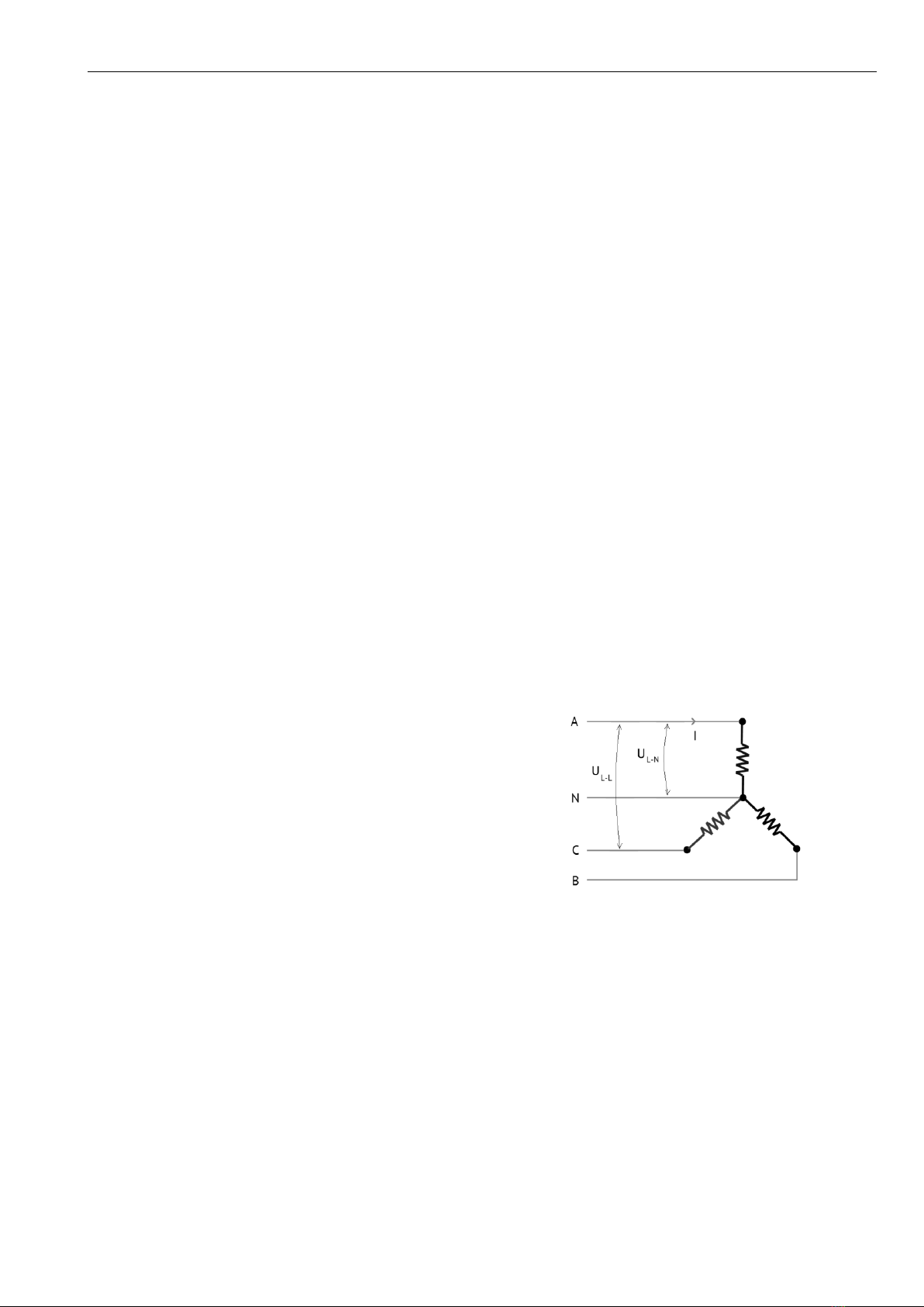
UL-L(UAB, UBC, UCA) –line-to-line voltage
UL-N(UA, UB, UC) - line-to-neutral voltage
I (IA, IB, IC) –phase current

General information
ENIP-2, manual, ENIP.411187.002. Rev. 11.2020 6
1General information
ENIP-2 measures the full set of three-phase electrical grid parameters. It includes RMS of
waveform combinations as well as the 1st harmonic parameters, e.g., effective voltage and
current (each phase and line to line), active, reactive and apparent power (each phase and
total), active and reactive energy import and export, power quality parameters. Digital
input-output and programmable logic functionality enables it to play major role in auto-
mation systems. ENIP-2 is able to exchange data via RS-485 (Modbus and IEC 60870-5-
101 protocols) communication port or Ethernet (Modbus, IEC 60870-5-104 and IEC-
61850 as an add-on option).
ENIP-2 is designed for use in SCADA and supervisory control centers of substations, power
stations, ships, industrial mills, oil and gas production. It can transmit data directly to
higher level of controlling system or through remote terminal unit (RTU), e.g., ENСS-3m,
ENСM-3.
High performance, high-quality signal processing and the possibility of synchronous
measurements of electrical grid parameters make ENIP-2 unique. High-quality measure-
ments are achieved by using our own advanced signal processing algorithms. Moreover,
ENIP-2 optionally supports IEC 61850 (MMS-server, GOOSE subscriber/publisher) and can
serve as a basic control unit for digital substation.
ENIP-2 configuration is supposed to be defined by «ES Configurator»software (here). It
allows to set required parameters for available interfaces and protocols and defining I/O
configuration. For more information, see chapter 6.
ENIP-2 is multifunctional, repairable, restorable device. It is designed for continuous op-
eration in industrial installations.
Manufacturer
Engineering Center "Energoservice"
26 Kotlasskaya St., 163046 Arkhangelsk, RUSSIA
tel.: +7(8182)64-60-00, +7(8182)65-75-65; fax: +7(8182)23-69-55
Electromagnetic compatibility certificate №E032/02
Directive 2011/65EUof the European Parliament and of the Council
of 8 June 2011 on the restriction of the use of certain hazardous
substances in electrical and electronic equipment.
EN 61010-1:2010, EN 61000-4-3, EN 61000-4-4, EN 61000-4-5, 61000-
4-6, 61000-4-8, 61000-4-11.

General information
ENIP-2, manual, ENIP.411187.002. Rev. 11.2020 7
Conformity
The following table contains standards and certification of device.
Safety
IEC 61010-1
Certifications
CE
EMC
№
Standard
Level
Class
1
IEC 61000-6-5
-
-
2
IEC 61000-4-2
3
A
3
IEC 61000-4-3
3
A
4
IEC 61000-4-4
4
A
5
IEC 61000-4-5
4
A
6
IEC 61000-4-6
3
A
7
IEC 1000-4-8
5
A
8
IEC 1000-4-9
5
A
9
IEC 1000-4-10
5
A
10
IEC 61000-4-11
-
A
11
IEC 61000-4-29
-
A
12
IEC 61000-4-12
3*/4**
A
13
IEC 61000-4-13
3
A
14
IEC 61000-4-14
X (Special)***
A
15
IEC 61000-4-16
4
A
16
IEC 61000-4-17
3
A
17
IEC 61000-4-28
4
A
18
CISPR 22
-
A
19
CISPR 11
-
A-1
20
IEC 60255-5
-
-
* Periodic interference 0.1 and 1 MHz;
** Solitary interference 0.1 MHz;
*** ΔU=±0.2Un, Un–nominal voltage.

Design, dimensions, naming convention
ENIP-2, manual, ENIP.411187.002. Rev. 11.2020 8
2Design, dimensions, naming convention
ENIP-2 devices are manufactured in three models: Standard, Compact, PMU.
2.1 ENIP-2-…-X1 (Standard)
It is ENIP-2 in plastic case housing for DIN-rail mounting.
There are four modifications of ENIP-2 Standard:
Minimal –1xRS-485
Terminals: measuring inputs, power inputs, USB, digital interface RS-485.
Figure 2.1. ENIP-2-4X/X-X-A1E0-01

Design, dimensions, naming convention
ENIP-2, manual, ENIP.411187.002. Rev. 11.2020 9
Basic –2xRS-485, digital I/O
Basic modification boasts an additional RS-485, as well as 8 digital inputs, or set of 4
digital inputs and 3 outputs.
Plus 4 digital inputs, 3 digital outputs Plus 8 digital inputs
Figure 2.2 –ENIP-2-4X/X-X-A2E0-1(2)1
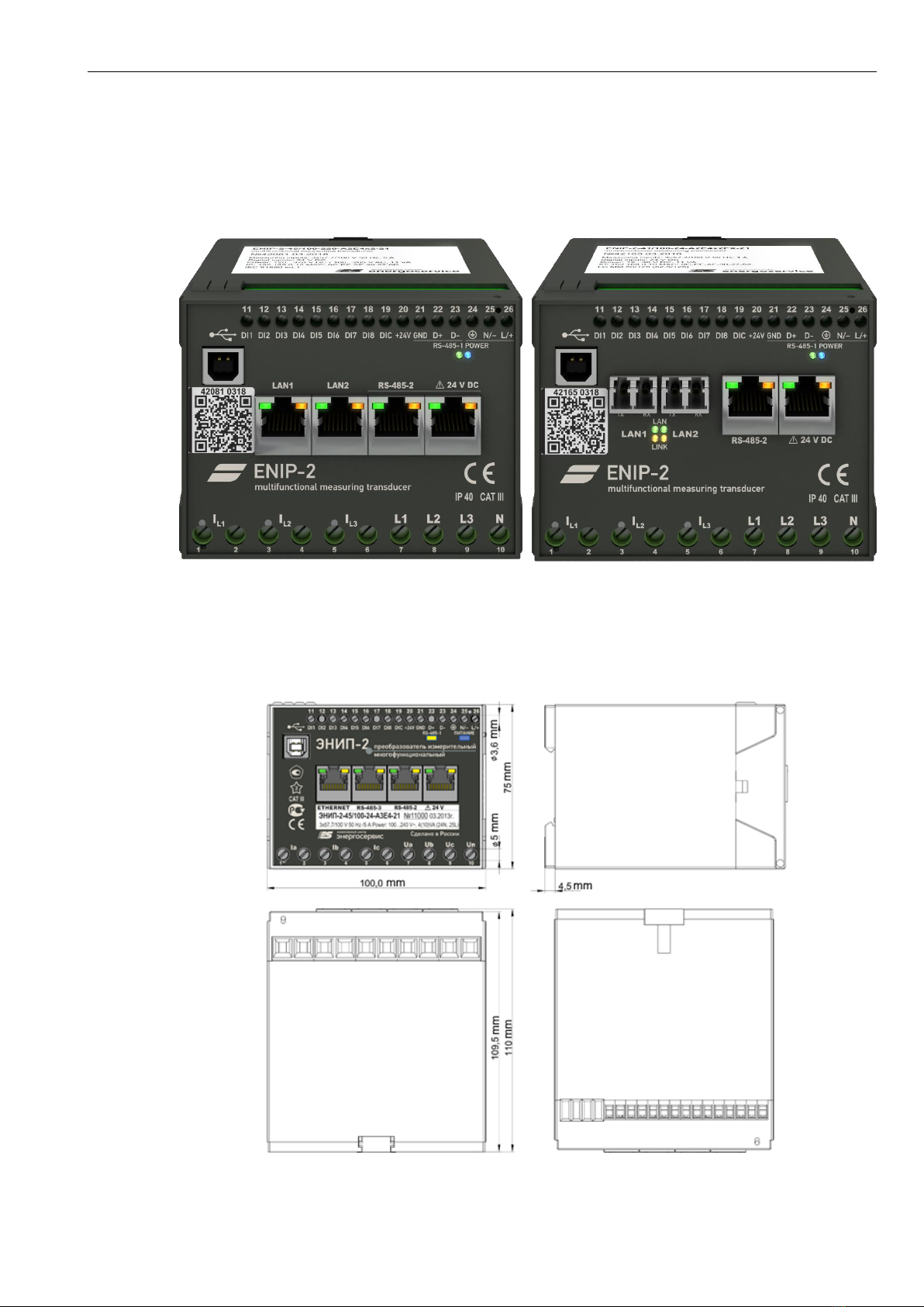
Extended –3xRS-485, Ethernet 100Base-T, 8 DI
Extended modification has three RS-485 (RS-485-3) and one Ethernet 100Base-T ports.
Figure 2.3. ENIP-2-4X/X-X-A3E4-21 (left) and ENIP-2-4X/X-X-A2SFP4-21 (right)
Design, dimensions, naming convention
ENIP-2, manual, ENIP.411187.002. Rev. 11.2020 10
Maximum –2xRS-485, 2xEthernet 100Base-T or Ethernet 100Base-FX, 8 DI
Maximum modification has two RS-485 and two Ethernet ports with RSTP and PRP.
2 Ethernet 100Base-TX 2 Ethernet 100Base-FX
Figure 2.4. ENIP-2-4X/X-X-A2E4x2(FX)-21
ENIP-2-XX/X-X-XX-X1 dimensions see on fig. 2.5.
Figure 2.5. Dimensions of ENIP-2 Standard (front panel belongs to ENIP-2-45/100-24-А3Е4-21)

Design, dimensions, naming convention
ENIP-2, manual, ENIP.411187.002. Rev. 11.2020 11
See the information below for ENIP-2 Standard ordering codes composing.
Design, dimensions, naming convention
ENIP-2, manual, ENIP.411187.002. Rev. 11.2020 12
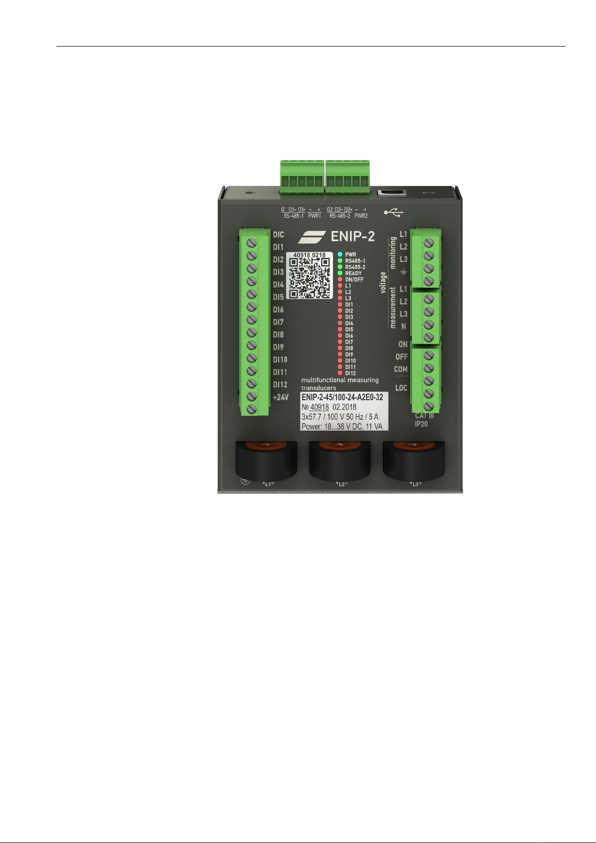
2.2 ENIP-2-…-32 (Compact)
It is in metal body for DIN-rail mounting (DIN-КР), or mounting with bracket (RM6-КР).
Figure 2.6. ENIP-2 Compact
ENIP-2 Compact has 12 DI, 3 DO, 2xRS-485, measuring inputs, voltage monitoring inputs.
Power supply voltage is 18…36 V DC.


Design, dimensions, naming convention
ENIP-2, manual, ENIP.411187.002. Rev. 11.2020 14
Figure 2.8. Dimension of ENIP-2 Compact (front panel belong to ENIP-2-45/100-24-А2Е0-32)

Features
ENIP-2, manual, ENIP.411187.002. Rev. 11.2020 15
3Features
3.1 General information
Analog current and voltage inputs are converted into analog voltage signals of lower
scale. These signals go to ADC. ADC performs analog-to digital conversion of instantane-
ous values of measured signals (40 measures per each period of industrial frequency
(50/60 Hz)). Measuring data is further passed on to microcontroller (MCU). ENIP-2 struc-
ture scheme is illustrated in fig. 3.1.
MCU performs:
•Electrical grid parameters calculation (using 50 ms “sliding window”measurement
calculation method) –instant measurements;
•Averaging of both measured and calculated parameters through “sliding window”
method (possible averaging time is 200, 500, 1000, 1500, 2000 ms) –averaged meas-
urements;
•Processing digital I/O;
•Data exchange with extension systems through the following protocols: Modbus
RTU, Modbus TCP, IEC 60870-5-104, IEC 60870-5-101, SNTP, SNMP, IEC 61850-8.1 (IEC
61850-8.1 is optional and is sold separately as an add-on).
Galvanic isolation of RS-485 interface is accomplished through interface converters IC1,
IC2, IC3. Built-in functionality of an MCU makes Ethernet port available for use as well.
Real-time clock support is also brought about by MCU.
ENIP-2 might be used for different connections (3- or 4-wire electrical grid, with or with-
out transformers). All wiring diagrams see in Appendix A1.
You can choose the current range needed using «ES Configurator».
Current range
(% of nominal)
Description
1…200%
It’s recommended range. For maximal accuracy ENIP-2 measure in two ranges -
1…70% and 70…200%. Switching between ranges is accompanied by a delay about
200 ms.
2…200%
Fast range. Measurement is provided without switching.
8…800%
Fault current range. Accuracy for low current is does not match the stated accuracy.

Features
ENIP-2, manual, ENIP.411187.002. Rev. 11.2020 16
Figure 3.1. ENIP-2 structure scheme
3.2 Measured parameters
3.2.1 ENIP-2 «Standard»and «Compact»provides real-time “Instant” (50 ms) and averaged
measurements. Averaging time could be set during the configuration procedure by means
of ES Configurator software (available 200, 500, 1000, 1500, 2000 ms periods).
Table 3.1. Available parameters
Parameter
Symbol
3-wire
connection*
4-wire
connection
RMS
Effective voltage
UA, UB, UC
-
+
Average effective voltage
UL-N
-
+
Effective line-to-line voltage
UAB, UBC, UCA
+
+
Average effective line-to-line voltage
UL-L
+
+
Effective current
IA, IB, IC
+
+
Average effective current
I
+
+
Active power
PA, PB, PC,
-
+
Total active power
P
+
+
Reactive power
QA, QB, QC
-
+
Total reactive power
Q
+
+
Apparent power
SA, SB, SC
-
+
Total apparent power
S
+
+

Features
ENIP-2, manual, ENIP.411187.002. Rev. 11.2020 17
Parameter
Symbol
3-wire
connection*
4-wire
connection
Active energy import
WP+
+
+
Active energy export
WP-
+
+
Reactive energy import
WQ+
+
+
Reactive energy export
WQ-
+
+
1st harmonic
Effective voltage**
UA1, UB1, UC1
-
+
Average effective voltage
UL-N1
-
+
Effective line-to-line voltage
UAB1, UBC1, UCA1
+
+
Average effective line-to-line voltage
UL-L1
+
+
Effective current
IA1, IB1, IC1
+
+
Average effective current
I1
+
+
Active power
PA1, PB1, PC1,
-
+
Total active power
P1
+
+
Reactive power
QA1, QB1, QC1
-
+
Total reactive power
Q1
+
+
Apparent power
SA1, SB1, SC1
-
+
Total apparent power
S1
+
+
Frequency
F
+
+
Phase angle phase A
cos/tg/A
+
+
Phase angle phase B
cos/tg/B
+
+
Phase angle phase С
cos/tg/C
+
+
Phase angle total
cos/tg/
+
+
Voltage zero sequence
U0
-
+
Voltage positive sequence
U1
-
+
Voltage negative sequence
U2
-
+
Voltage unbalance of the negative sequence K2U =U2
U1
K2U
-
+
Voltage distortion KU=√U2−U1ℎ2
U1ℎ
KU
-
+
Current zero sequence
I0
-
+
Current positive sequence
I1
-
+
Current negative sequence
I2
-
+
Current unbalance of negative sequence K2I =I2
I1
K2I
-
+
Current distortion KI=√I2−I1ℎ2
I1ℎ
KI
-
+
Total harmonic distortion THD=(P-P1)/P1
THD
-
+
Active power zero sequence
P0
-
+
Reactive power zero sequence
Q0
-
+
* «+» means that parameter available for the connection (Connection is configured by «ES Configurator»);
ENIP-2 measures and saves active and reactive energy in both forward and reverse direc-
tions. Maximum energy value is 99999999.9 Wh (varh). In case of overflow, it starts count-
ing from zero.

Features
ENIP-2, manual, ENIP.411187.002. Rev. 11.2020 18
ENIP-2 is not certificated as energy meter, nevertheless, its accuracy class is 0.2S (energy
measurement error for 0.01Irated is 0.35%, and for Irated –0.001%).
3.2.2 ENIP-2 (PMU) supports phasor measurement as defined by IEEE C37.118. Data rate up to
100 frames per second.
Measured values:
Table 3.1
Parameter
Symbol
Phasor
RMS
Effective voltage
UA, UB, UC
+
+
Effective line-to-line voltage
UAB, UBC, UCA
-
+
Effective current
IA, IB, IC
+
+
Active power
PA, PB, PC
-
+
Total active power
P
-
+
Reactive power
QA, QB, QC
-
+
Total reactive power
Q
-
+
Apparent power
SA, SB, SC
-
+
Total apparent power
S
-
+
cos φ
cosφA, cosφB, cosφC
-
+
Frequency
F
-
+
Frequency А
Fa
-
+
Frequency B
Fb
-
+
Frequency C
Fc
-
+
ROCOF
dF
-
+
ROCOF А
dFa
-
+
ROCOF B
dFb
-
+
ROCOF C
dFc
-
+
Voltage zero sequence
U0
+
-
Voltage positive sequence
U1
+
-
Voltage negative sequence
U2
+
-
Current zero sequence
I0
+
-
Current positive sequence
I1
+
-
Current negative sequence
I2
+
-

Features
ENIP-2, manual, ENIP.411187.002. Rev. 11.2020 19
3.3 Digital signals
The maximum number of digital signals (called «DIO») for ENIP-2 is 32. These include DI,
DO, configurable setpoints, logical expressions, goose subscribers, diagnostics (table 3.2).
Every DIO is configured independently. For details see «ES Configurator manual».
Table 3.2
DIO
Description
Digital output
Built-in or external DO
Digital input
Built-in or external DI
Setpoints
Configurable setpoints for any parameters.
Logical expressions
Use any DIO for switchgear interlocking protection.
Goose subscriber
Subscribe to GOOSE-messages IEC61850 8-1
Diagnostic
Errors monitoring
3.3.1 Digital outputs
ENIP-2 Standard and Compact provides switchgear equipment control using built-in dig-
ital outputs or using extension ENMV-1 modules, which are connected to RS-485-2 of
ENIP-2.
Table 3.3
ENIP-2 Standard
ENIP-2 Compact
Extension module
ENMV
Type
3 SSR output
3 (electromagnetic + high power
solid-state) relay output
electromagnetic relay
or SSR output
Maximum
voltage
300 V DC
250 V AC
250 V DC/AC
250 V AC
Maximum
current
100 mA DC/AC
impulse 200 ms –9 А
short impulse - 6 А
long impulse - 5 А
longtime - 1.3 А
100 mA DC/AC (SSR)
7 A AC (EMR)
For built-in DO use intermediate relay if current is more than 100 mA:
−AC: Finder 55.33.8.230.0010, Relpol (R4-2014-23-5230-WT) or similar;
−DC: Finder 55.33.9.220.0010, Relpol (R4-2014-23-1220-WT) or similar.
Four or less ENMV modules can be connected via RS-485-2 (1 ENMV-2-4/3R-220-А1 plus
3 ENMV-1 or 4 ENMV-1). One ENMV-1-4/3R can control only one electrical switch.
ENIP-2 and ENMV communicate via Modbus RTU protocol.
ENIP-2 supports Single command (<45>), Double command (<46>) over IEC 60870-5-101
or IEC 60870-5-104 and Force Single Coil (the function code 5) over Modbus.

Features
ENIP-2, manual, ENIP.411187.002. Rev. 11.2020 20
Figure 3.2. Connection of ENIP-2 and ENMV
3.3.2 Digital inputs
ENIP-2 is equipped with 0, 4, 8 or 12 built-in digital inputs with debounce filter. Contacts
for digital inputs can be both wet and dry (fig. 3.3). Dry contacts are powered by built-in
24 V DC supply.
“wet” contacts
“dry” contacts
Figure 3.3. Wet and dry contacts for DI
ENIP-2 can contain up to 32 DI. These include its own DI (built-in) as well as DI from
extension ENMV modules connected to ENIP-2 via RS-485-2 (up to 4 modules).
ENIP-2 has events log of DI statuses. Each record of event log is marked with time stamp
with 1 ms resolution.
DI statuses are transferred over IEC 60870-5-101, IEC 60870-5-104 in Single point or
Double point.
Table 3.4
ENIP-2-XX/X-X-XX-X1
ENIP-2-XX/X-X-XX-
X1(220)
ENIP-2-XX/X-X-XX-32
Type
0, 4 or 8 wet contact
0, 4 or 8 wet contact
12 wet contact
Voltage
20…250 V DC
200…250 V AC
18…36 V DC
Current
2 mA
2 mA
2 mA
This manual suits for next models
1
Table of contents
Popular Transducer manuals by other brands


Fishman
Fishman SBT-C installation guide

Kanomax
Kanomax 6332 Operation manual

KYOWA
KYOWA DTS-A-100 instruction manual

HBK
HBK AED 9101D quick start guide

Nordson
Nordson Eclipse EPC-30 Series instruction sheet

S+S Regeltechnik
S+S Regeltechnik PREMASREG 7100 VA ID Series Operating Instructions, Mounting & Installation