Esatto ECG604E User manual

Version
V1.0 1022
Everything you need
for your Gs Cooktop
is in this User Mnul
Model/s
ECG604E

User Manual
2
Welcome
Congrtultions on purchsing your new Gs Cooktop. The Estto brnd is
proudly distributed within Austrli by Residenti Group Pty Ltd.
Plese refer to the wrrnty crd t the rer of this mnul for informtion
regrding your product’s prts nd lbour wrrnty, or visit us online t:
www.residenti.group
At Residenti Group, we re customer obsessed nd our Support Tem re
there to ensure you get the most out of your pplince. Should you wnt to
lern more bout your new gs cooktop, it's fetures or importntly tking
cre of the pplince, our Support Tem re here to help.
You cn use our online Support Centre t nytime by visiting:
http://support.residentigroup.com.u
Or you cn contct us vi phone by diling: 1300 11 HELP (4357).
It is importnt tht you red through the following use nd cre mnul
thoroughly to fmilirise yourself with the instlltion nd opertion
requirements of your pplince to ensure optimum performnce.
Agin, thnk you for choosing n Estto pplince nd we look forwrd
to being of service to you.
Kind Regrds,
The Residenti Tem
Residenti roup
—
Head Office
165 Brkly Avenue
Burnley, Victori
Austrli 3121
—
ACN
600 546 656
—
Online
residenti.group
www.estto.house
@estto.house
—
Postage
PO Box 5177
Burnley, Victori
Austrli 3121
—
Telephone
1300 11 4357
www.estto.house

esatto.house
3
Pge 2
Welcome
Pge 4
Sfety Instructions
Pge 6
Product Overview
Pge 7
Before First Use
Pge 8
Using Your
Cooktop
Pge 9
Burners
Pge 10
Clening Cre
Pge 11
Troubleshooting
Pge 12
Technicl Dt
Pge 13
Instlltion
Instructions
Pge 16
Gs Connection
Pge 19
LPG Conversion
Pge 20
Electricl
Connection
Pge 21
Testing Applince
Opertion
Pge 23
Purchse Detils
Pge 24
Wrrnty
Contents

User Manual
4
IMPORTANT SAFETY INSTRUCTIONS
READ CAREFULLY AND KEEP
FOR FUTURE REFERENCE
Red this mnul thoroughly before rst use,
even if you re fmilir with this type of product.
The sfety precutions enclosed herein reduce
the risk of re, electric shock nd injury when
correctly dhered to. Mke sure you understnd
ll instructions nd wrnings.
Keep the user mnul in sfe plce for future
reference, long with the completed wrrnty
crd nd purchse receipt. If you sell or trnsfer
ownership of this product, pss on these
instructions to the new owner.
Alwys follow bsic sfety precutions nd
ccident prevention mesures when using n
electricl pplince. The following sttements you
will see in this booklet hve these menings:
WARNING: Indicting informtion concerning
your personl sfety.
CAUTION: Indicting informtion on how
to void dmging the pplince, benchtop
or cbinetry.
IMPORTANT: Indicting tips nd informtion
bout use of the pplince.
USAGE CONDITIONS AND RESTRICTIONS
• Domestic use only: This pplince is intended
for indoor household use only. It is not intended
for commercil, industril or outdoor use. It is
not intended for use in recretionl vehicle.
• Purpose: Do not use this pplince for nything
other thn its intended purpose. Other uses re
not recommended nd my cuse re, electric
shock or personl injury.
• Attchments: The use of ttchments is not
recommended by the pplince mnufcturer
nd distributor s they my be hzrdous.
• Improper use: Dmge due to improper use,
or repirs mde by unqulied personnel will
void your wrrnty. We ssume no libility
for ny eventul dmges cused by misuse
of the product or noncomplince with these
instructions.
BEFORE USING YOUR APPLIANCE
This mnul explins the proper use of your new
Estto cooktop. Plese red this mnul crefully
before using the product. This mnul should be
kept in sfe plce for hndy reference.
This rngehood is domestic pplince which
hs been mnufctured nd tested to comply
with Austrlin nd New Zelnd Stndrd
AS/NZS 5263.
This cooktop must only be instlled in ccordnce
with the instructions provided. Incorrect
instlltion my cuse hrm to persons, dmge
property nd void the product’s wrrnty.
Red the following crefully to void dmge
or injury.
IMPORTANT: Check for ny dmge or
mrks. If you nd the pplince is dmged
or mrked, you must report it within 7 dys if
you wish to clim for dmge/ mrks under the
mnufcturer’s wrrnty. This does not ect
your sttutory rights.
WARNING: Follow these instructions crefully
to void injury or dmge to your pplince.
• Do not llow pots to boil dry, s dmge to both
pn nd cooktop my result.
• Do not operte the cooktop for n extended
period without pot or pn on the burner.
Sfety Instructions

esatto.house
5
• Do not llow lrge cookwre to overhng the
cooktop onto djcent benchtop. This will cuse
scorching to the benchtop surfce.
• Do not llow cooking pots or pns to intrude
into the re which is close to the controls.
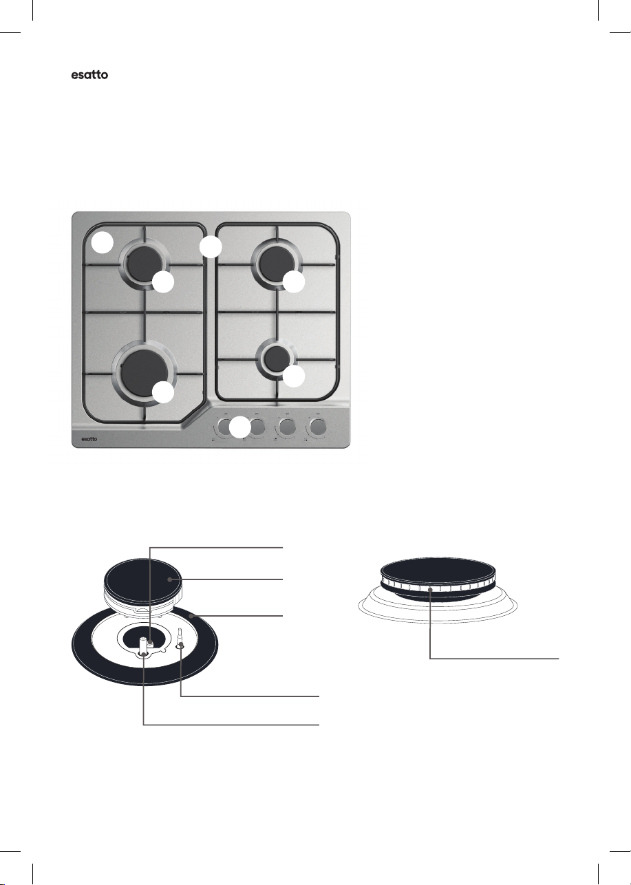
• Ensure burner bodies nd trivets re properly
locted on the cooktop (i.e. correctly ssembled
nd positioned).
CAUTION: Follow these instructions crefully
to void n electric shock or re.
It is importnt to use your cooktop sfely. Check
these sfety points before using your cooktop.
• This pplince is not intended for use by
persons (including children) with reduced
physicl, sensory or mentl cpbilities, or lck
of experience nd knowledge, unless they hve
been given supervision or instruction concerning
use of the pplince by person responsible for
their sfety.
• Children should be supervised to ensure they do
not ply with this pplince.
• During use, this pplince becomes hot.
Cre should be tken to void touching hot
surfces. To void burns, young children should
be kept wy.
• This pplince must not be used s
spce heter.
• Keep vents cler of obstructions.
• In order to void re, this pplince must be
kept clen.
• Do not spry erosols in the vicinity of this
pplince while it is in opertion.
• Do not store mmble mterils on or under
this pplince, e.g. erosols.
• Do not remove the trivet nd enclose the burner
with wok stnd s this will concentrte nd
deect het onto the burner.
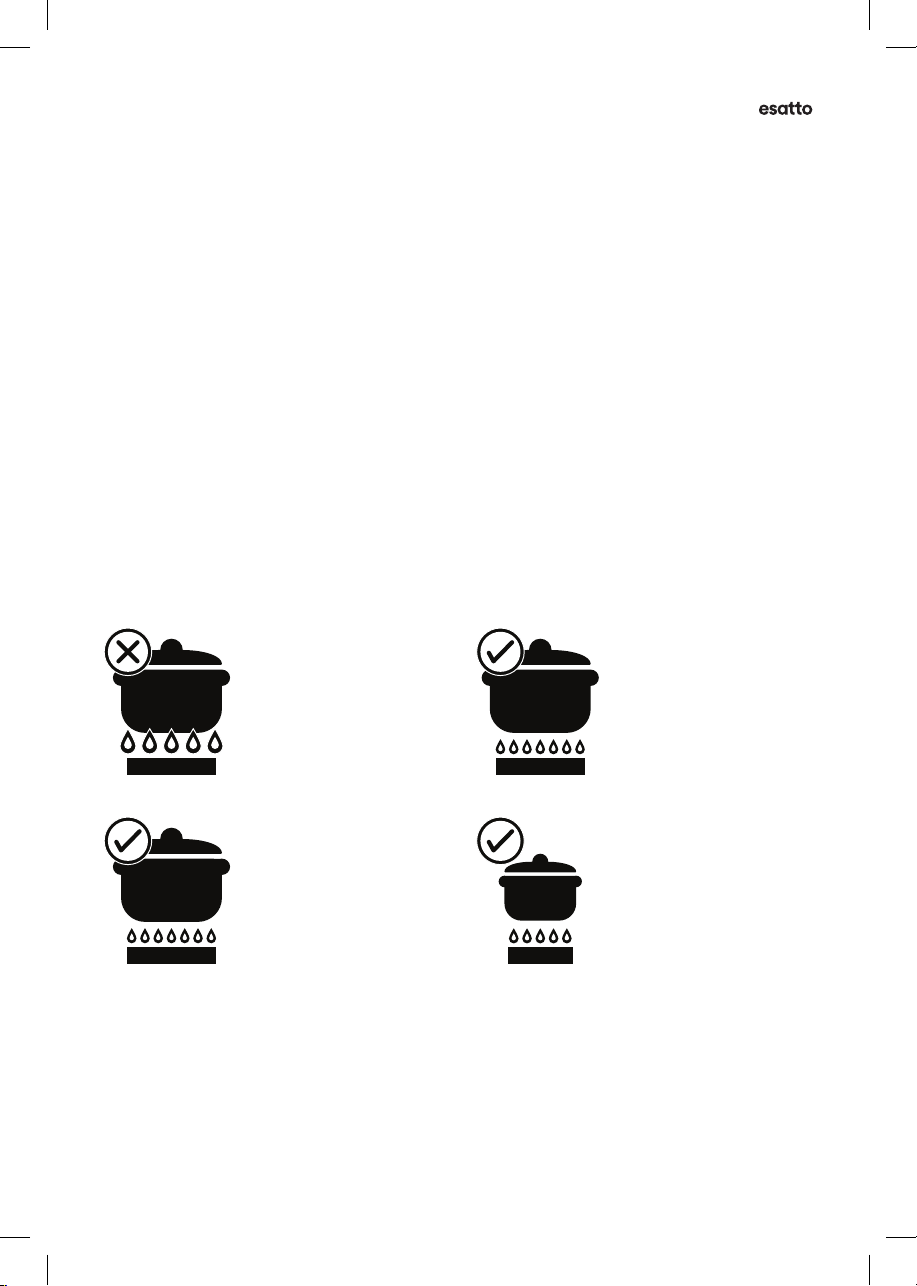
• Do not use lrge pots or hevy weights
which cn bend the trivet or deect me onto
the burner.
• Do not plce nything, e.g. sbestos mt
between pn nd trivet s serious dmge to
the cooktop my occur.
• For mximum stbility, ensure pots nd pns re
centrlly locted on the trivets.
• Hndles should be turned wy from the front
of the bench to void ccidents.
• Do not modify this pplince.
• Only models tted with me sfegurd
cn be used in mrine crft, crvns
or mobile homes.
CAUTION: In the event of gs lek, tke the
following ctions:
• Do not turn on the room light.
• Do not switch on/o ny electricl pplinces
nd do not touch ny electric plugs.
• Do not use telephone.
1. Stop using the product nd close the
middle vlve.
2. Open the window to ventilte.
3. Contct our service centre by using mobile
phone outside.
NOTE: The fuel gs contins mercptn. In the
event of gs lek, it will smell like rotten eggs or
grlic—even if there is only 1/1000th of the gs is
in the ir.
UNPACKING
During trnsporttion, protective pckging ws
used to protect the pplince ginst ny dmge.
After unpcking, plese dispose of ll elements of
pckging in wy tht will not cuse dmge to
the environment.
All mterils used for pckging the pplince re
environmentlly friendly; they re 100% recyclble
nd re mrked with the pproprite symbol.
CAUTION: During unpcking, the pckging
mterils (polythene bgs, polystyrene pieces,
etc.) should be kept out of rech of children.
DISPOSAL OF THE APPLIANCE
Old pplinces should not simply be disposed
of with norml household wste nd should be
delivered to collection nd recycling centre for
electric nd electronic equipment. A symbol shown
on the product, the instruction mnul or the
pckging shows tht it is suitble for recycling.
Mterils used inside the pplince
re recyclble nd re lbelled with
informtion concerning this.
By recycling mterils or other prts
from used devices you re mking
signicnt contribution to the
protection of our environment.
Informtion on pproprite disposl
centres for used devices cn be
provided by your locl uthority.

User Manual
6
THE BURNER
Figure 2A
Product Overview
Burner Flme Ports
Ignition Sprk Plug
Flme Sfegurd Sensor
Skirt
Burner
Injector
Note: The images in this user manual are for reference only. Your appliance may appear dierently.
YOUR COOKTOP
Figure 1A — ECG604E
A
B
D
E
C
E
F
KEY
A. Stinless Steel Hob
B. Burner Control Knobs
C. Enmel Trivets
D. Auxiliry Burner
E. Semi Rpid Burner
F. Rpid Burner
COOKTOP COMPONENTS
ACCESSORIES
Your Estto cooktop is supplied with:
1 × Cooktop
1 × Auxiliry pn support
1 × Voltge regultor vlve
4 × Injectors
1 × Pressure joint
4 × Brckets
4 × Seling strips
4 × Screws
1 × Elbow
1 × User Mnul
1 × Quick Strt Guide
Figure 2B

esatto.house
7
INSTALLATION
• An uthorised person must instll this pplince
nd MUST provide Certicte of Complince.
This certicte should be retined long with
purchse informtion.
• Before using the cooktop, ensure tht ll
pcking mterils re removed from the
pplince.
• In order to void ny potentil hzrd, the
instlltion instructions in this booklet, nd ny
lbels on the pplince must be followed.
• Ensure tht ll specied vents, openings nd ir
spces re not blocked.
• Where the pplince is built into benchtop,
the benchtop mteril must be cpble of
withstnding 85°C.
• Ensure tht the duplicte rting lbel
(in the instruction pck) is ttched to
redily ccessible djcent surfce, so tht the
cooktop cn be esily identied in the cse of
service cll.
SERVICING
• Servicing MUST only be crried out by
uthorised personnel.
• To mintin sfe opertion, it is recommended
tht the product be inspected every ve yers
by n uthorised service person.
• If the supply cord is dmged, it must be
replced by the mnufcturer, its service gent
or similrly qulied persons in order to void
hzrd.
WARNING: Never instll cooktop tht hs
been dmged. Plese contct our Service Tem
for ssistnce.
CLEANING
• Alwys ensure the pplince is turned o
before clening.
• This pplince contins luminium ttings.
Do not use custic bsed cleners.
• Do not use stem cleners s this my cuse
moisture build up on electricl components.
• Alwys clen the pplince immeditely fter
ny food spillge.
• Do not plce ny components in dishwsher.
• Refer to the Clening Cre section on pge 10
of this user mnul for instructions on clening
nd mintining your stinless steel hob pnel.
CAUTION: Never plce burners or trivets in
dishwsher.
Before First Use

User Manual
8
CONTROLS
Ech burner is controlled by control knob.
The mrkings on the control pnel indicte which
burner the knob controls, nd the setting for tht
burner (See Figure 3).
STANDARD BURNER
Figure 3
NOTE: Gs controls turn nticlockwise from ‘OFF’
nd hve limited movement.
LIGHTING BURNERS
Electronic ignition: These cooktops re tted with
mins powered ignition. When the pplince hs
been connected nd the power is on, depressing
ny knob will relese sprks to ll burners.
CAUTION:
• Keep hnds cler of burners when lighting.
• If burner does not light within 5 seconds, turn
knob to ‘OFF’ position, wit to llow gs to
disperse nd then try lighting gin.
• Burners MUST be operted between ‘1’ nd ‘9’
settings only.
To light burner, the knob must be turned to the
position, then pushed down s fr s possible
for pproximtely 5 seconds. If the me goes
out when the knob is relesed simply depress the
knob gin, this time holding it down with slightly
more force for the sme length of time.
The height of the me cn be vried by turning
the control knob towrd the ‘1’ position.
In the bsence of electricl power, crry out the
ignition directly to the burner with hnd held
ignition source.
Using Your Cooktop
Note: The diagrams in this user manual are for reference only. Your appliance may appear dierently.

esatto.house
9
Burners
CHOICE OF BURNER
For your convenience there is choice of burners
to choose from:
• A smll Auxiliry burner for specil low het
nd slow cooking. Minimum pn size 120mm
(Mximum 160mm).
• Two medium Semi-Rpid burners for norml
cooking nd simmering. Minimum pn size
160mm (Mximum 180mm).
• A lrge Rpid burner for fst heting nd lrge
pots nd pns. Minimum pn size 200mm
(Mximum 240mm).
To conserve gs plce the pn centrlly over the
burner nd djust the me so tht it does not
extend pst the edge of the pn (Figure 4). Do not
boil food too rpidly. A vigorous boil will not cook
food ny fster, nd will wste energy.
Figure 4
POTS AND PANS
All common pots nd pns; luminium,
stinless steel, cst iron, cermic, etc., my
be used on your new gs cooktop. Ensure tht
the pots or pns re stedy nd hve t bses
to void dngerous spill-over of hot liquids nd
wsted energy.
CAUTION:
Never use sbestos mts, wire mts or grids,
or luminium foil s it cn led to overheting,
crcked enmel or broken glss. The wrrnty will
be void if these items re used nd cuse filure.
INCORRECT
A me tht is too high will
cuse gs wstge long
with possibility of heting
or dmge to your hndles.
CORRECT
For lrge burner,
use lrge utensil.
CORRECT
A correct me height will
sve gs usge.
CORRECT
For smll burner,
use smll utensil.

User Manual
10
Clening Cre
CAUTION:
Ensure the pplince is o nd hs cooled down
before clening.
TRIVETS
Persistent stins my require rubbing with
nylon scourer or cremed powder clensers.
Household enmel cleners re vilble, follow
the mnufcturer’s instructions in their use.
Hrsh brsive cleners, powder cleners,
steel wool or wx polishes should not be used.
STAINLESS STEEL HOB
The stinless steel hob my discolour over
time. This is norml due to the high cooking
tempertures. Ech time the cooktop is used, it
should be clen with product tht is sfe nd
suitble for stinless steel, such s soft cloth or
sponge with detergent nd wrm wter.
CAUTION: Try to clen up nd remove spillges
immeditely, while the hob is still hot! Especilly
sugr nd foods with high sugr content
(eg. jm), melted plstics nd foil, ll of which
cn dmge the hob if left. Dry the the surfce
thoroughly fter clening.
If the hob requires extensive clening:
• Use hob clener product fter there hs been
sucient time llowed for the hob to cool.
Shke the bottle nd pply smll quntity of
clener directly onto the hob.
Rub clen using dmp cloth or pper towels.
• Use dmp cloth to remove ll remining
trces of the clener, which could otherwise
burn on when the hob is next used. Wipe the
hob dry.
TRIVETS AND BURNERS
These cn ll be lifted o nd removed for
seprte clening.
CAUTION: When retting the burners, ensure
tht they re correctly seted.
Ensure burners re thoroughly dried fter clening
or spillge. When clening the burners, ensure
tht ll the me ports re free of ny blockge
(refer to Figure 2B on pge 6). If necessry, use
toothpick or brush to cler ports. The outer
surfce of the burner cps hve polished
nish nd extr cre needs to be tken to void
scrtching this surfce during clening. In
instnces of hevy soiling, it my be necessry to
pply non-brsive clening compound nd rub
with cloth until the soiling is removed nd then
nish with soft, dry cloth.
WARNING:
NEVER plce trivets or burners in the dishwsher.
IGNITION SPARK PLUG
FLAME SAFEGUARD SENSOR
Gently clen the ignition sprk plug nd me
sfegurd sensor with dmp cloth to void
lighting diculties. Ensure tht they re dry
before use.
INJECTOR
Ensure the injector remins free of ny foreign
mteril. If necessry, use thin piece of wire to
cler the orice.

esatto.house
11
Troubleshooting
If you hve problem with the cooktop, check the tble below. You my be ble to solve the problem
nd this will sve you from pying for service cll. You will hve to py for service cll even in the
wrrnty period if the problem is one listed below.
Tble 1
PROBLEM POSSIBLE CAUSE SOLUTION
Burner will not light
even though the
sprker is working
Knob not held down long enough in ‘9’
position for me sfegurd.
Repet lighting procedure nd
hold knob down for 5 seconds in
‘9’ position. (Refer pge 8).
Gs supply vlve turned o. Turn on gs supply to pplince.
Wrong knob turned.
Ensure the knob you re turning
corresponds to the burner you
wnt to light.
Port blockge in ignition re. Ensure tht ports in ignition re
re clen nd dry.
Ignition sprk plugs wet or dirty. Dry or clen ignition sprk plugs.
No sprk is obtined
when control knob is
ctivted
Electricity supply is disconnected or
switched o.
Switch on electricity
or check fuses.
Ignition sprk plugs wet or dirty. Dry or clen ignition sprk plugs.
Flmes uneven or
tending to lift
Flme ports blocked or wet. Clen or dry me ports.
Burner cp incorrectly tted. Ensure this component is
tted correctly.
Flmes not stying on
when knob
is relesed
Knob not held down long enough
in ‘9’ position for me sfegurd
to engge.
Repet lighting procedure nd
hold knob down for 5 seconds in
‘9’ position. (Refer pge 8).
Knob not set between ‘1’ nd ‘9’ Knob MUST be set between
these positions.
Dirt or spillge on me
sfegurd sensor. Clen me sfegurd sensor tip.
Low het, slow
cooking
Incorrect cooking pot or pn
being used. Refer to Figure 4 (pge 9).
Benchtop or knobs
overheting
Incorrect cooking pot or pn
being used. Refer to Figure 4 (pge 9).
Pot or pn not locted
on burner properly.
Ensure pot or pn is centrlly
locted on burner.

User Manual
12
Technicl Dt
Tble 2
FEATURES ECG604E
Burners 4
Wok No
Ignition 220–240V~
Trivet Enmel
Hob Mteril 201 Grde Stinless Steel
Fetures Continous Ignition Device
Flme Filure Sfety Yes
Gs Connection G1/2 thred
Gs Types NG (LP conversion
kit supplied)
COOKTOP PHYSICAL DIMENSIONS mm
Width 600
Depth 510
Height 95
CUT OUT DIMENSIONS mm
Width 560
Depth 490
ENERGY RATING NG MJ/h
Auxiliry burner 4.3
Semi Rpid burner × 2 6.3
Rpid burner 10.8
Totl MJ/h 27.7
• This product is subject to continuous improvement,
specications are subject to change without prior notice.
• This product was tested in accordance with the following standards:
AS/NZS 60335.2.102: 2018 & AS/NZS 60335.1: 2020

esatto.house
13
Instlltion Instructions
INSTALLATION PROCEDURE
• Do not modify this pplince.
• WARNING: This pplince must be instlled
by n uthorised technicin or instller.
• Prior to instlltion, ensure tht the locl distribution conditions (nture of the gs nd
gs pressure) nd the djustment of the pplince re comptible.
• The djustment conditions for this pplince re stted on the lbel (or dt plte)
• This pplince is not connected to combustion products evcution device. It
should be instlled nd connected in ccordnce with current instlltion regultions.
Prticulr ttention should be given to the relevnt requirements regrding ventiltion.
• Before instlling, turn o the gs nd electricity supply to the pplince.
• All pplinces contining ny electricl components must be erthed.
• Ensure tht the gs pipe nd electricl cble re instlled in such wy tht they do not
touch ny prts of the pplince which my become hot.
• Gs pipe or connector shouldn’t be bent or blocked by ny other pplinces.
• Check the dimensions of the pplince s well s the dimensions of the gp to be cut in
the kitchen unit.
• The pnels locted bove the work surfce, directly next to the pplince, must be mde
of non-mmble mteril. Both the strtied surfcing nd the glue used to secure it
should be het resistnt, to prevent deteriortion.
• Turn on pplince tp nd light ech burner. Check for cler blue me without yellow
tipping nd if burners show ny bnormlities check the following;
– Burner lid is on correctly
– Flme spreder is positioned correctly
– Burner verticlly ligned with injector end
• A full opertionl test nd test for possible lekges must be crried out by the instller
fter instlltion.
• The exible hose shll be tted in such wy tht it cnnot come into contct with
movble prt of the housing unit nd does not pss through ny spce susceptible of
becoming congested.
• Grese crnes produced t the fctory to meet the requirement of ll life hob.
CAUTION: Cooktops re supplied set up for nturl gs (NG). To use on LPG, the injectors
must be chnged using the conversion kit supplied. Refer LPG Conversion on pge 19.
Figure 5 – ECG604E
600
510
490
95
560
Gas Supply
Connection
200
60
200

User Manual
14
INSTALLATION PROCEDURE
• When tting the cooktop with rngehood bove, refer to the instlltion requirements
of the rngehood for clernces required.
• This pplince is to be built into kitchen unit or 600mm worktop, provided the
following minimum distnces re llowed;
• The edges of the cooktop must be minimum distnce of 60mm from side or rer wll.
• Adjcent wlls, cupbords nd protection for combustible mterils: Ensure tht the
pplince is instlled in ccordnce with AS/NZS 5601.1, or AS/NZS 5601.2 with regrd
to clernces to combustible surfces nd mterils, nd clernces to rngehoods nd
exhust fns.
• Clernces to combustible surfces my be reduced if combustible surfces re
protected in ccordnce with AS/NZS 5601.1, or AS/NZS 5601.2.
• 400mm between the cooktop surfces, providing tht the underside of the horizontl
surfce is in line with the outer edge of the cooktop. If the underside of the horizontl
surfce is lower thn 400mm, then it must be t lest 50mm wy from the outer edges
of the cooktop.
• 50mm clernce round the pplince nd between the cooktop surfce nd ny
combustible mterils.
• A brrier must be instlled to prevent ccidentl contct with the cooktop bse,
where the bse of the cooktop is ccessible from below (i.e. Inside cupbord, etc.).
A minimum clernce of 25mm must be mintined between the bse nd the brrier.
This brrier my be mde of ny non-combustible, rigid mteril.
• You must hve gp of t lest 25mm nd t most 74mm between the underneth of
the pplince nd ny surfce tht is below it.
• Brrier protection is not necessry if the product is instlled bove n underbench oven
or similr pplince nd/or if the cupbord construction is such tht the underside of
the cooktop is not ccessible.
• An oven must hve forced ventiltion to instll cooktop bove it. Check the dimensions
of the oven in the instlltion mnul.
• The cut out size must obey the indiction.
• Ensure that there is an earthed power outlet within 900mm of the rear right hand side of
the cooktop when installed. This should be accessible at all times.
• A self-adhesive Foam Tape has been provided to act as a sealing agent and is to be
placed around the edge of the hob underside. Ensure that there are no gaps in the Foam
Tape. Take care to ensure that the seals meet without overlapping. The thickness of this
Foam Tape is 3mm and the width is 10mm.
Positioning
The edges of the hob must be a minimum distance of mm from a side or
rear wall.
700 mm between the highest point of the hob surface (including the burners)
and the underside of any horizontal surface directly above it.
400 mm between the hob surfaces, providing that the underside of the
horizontal surface is in line with the outer edge of the hob. If the underside of
the horizontal surface is lower than 400 mm, then it must be at least 50 mm
away from the outer edges of the hob.
50 mm clearance around the appliance and between the hob surface and any
combustible materials.
45 mm
60
You must have a gap of at least 25 mm and at most 74 mm between
the underneath of the appliance and any surface that is below it.
16
o
o
o
o
o
CLEARANCES REQUIRED
WHEN FITTING THE HOB
WITH A COOKER HOOD ABOVE
900mm
700mm
400mm
400mm
FO 0813
60mm
480mm
in
0
.
0mm
M
2
This appliance is to be built into a kitchen unit or 600mm worktop,providing
the following minium distances are allowed;
- An oven must have forced ventilation to install a hob above it.
- Check the dimensions of the oven in the installation manual.
- The cut out size must obey the indication.
830mm
12
INSTALLATION INSTRUCTIONS CONT.
INSTALLING THE APPLIANCE
•Remove the pan supports, the burner lid and
flame spreader and carefully turn the appliance
upside down and place it on a cushioned mat.
Take care that the Ignition devices and flame
supervision devices are not damaged in this
operation.
•Apply the sponge provided around the edge of
the appliance.
•Do not leave a gap in the sealing agent or
overlap the thickness.
WARNING!
DO NOT use a silicon sealant to seal the appliance
to the bench top.
This will make it difficult to remove the appliance
from the aperture in future, particularly if it needs to
be serviced.
1. Place the bracket (B) over the holes that match
the size of the screws. There are one set of screw
holes in each corner of the cooktop.
2. Slightly tighten a screw (C) through the bracket
(B) so that the bracket is attached to the hob, but
so that you can still adjust the position. Carefully
turn the hob back over and then gently lower it
into the aperture hole that you have cut out.
3. On the underneath of the hob, adjust the
brackets into a position that is suitable for
your worktop.
Then fully tighten the screws (C) to secure the hob
into position.
Installing the appliance
Bottom view
of the screws.There are one set of screw holes in each
corner of the hob (H) .
Slightly tighten a screw (C) through the bracket (B) so
that the bracket is attached to the hob, but so that you
can still adjust the position
.
.2 Carefully turn the hob back over and then gently lower
it into the aperture hole that you have cut out.
.3 On the underneath of the hob, adjust the brackets into
a position that is suitable for your worktop.
Then fully tighten the screws (C) to secure the hob into
position.
(A) SEALING STRIP
(C) SCREW (B) BRACKET
17
Remove the pan supports, the burner lid
and flame spreader and carefully turn the
appliance upside down and place it on a
cushioned mat.
Take care that the Ignition devices and
flame supervision devices are not damaged
in this operation.
2. Apply the sponge provided around the
edge of the appliance.
3.
1.
Do not leave a gap in the sealing agent or
overlap the thickness.
3ODFHWKHEUDFNHW %RYHUWKHKROHVWKDWPDWFKWKHVL]H
7KLVZLOOPDNHLWGLI¿FXOWWRUHPRYHWKH
DSSOLDQFHIURPWKHDSHUWXUHLQIXWXUH
SDUWLFXODUO\LILWQHHGVWREHVHUYLFHG
Do not use a silicon sealant to seal the
appliance against the aperture.
Installing the appliance
of the screws.There are one set of screw holes in each
corner of the hob (H) .
Slightly tighten a screw (C) through the bracket (B) so
that the bracket is attached to the hob, but so that you
can still adjust the position
.
.2 Carefully turn the hob back over and then gently lower
it into the aperture hole that you have cut out.
.3 On the underneath of the hob, adjust the brackets into
a position that is suitable for your worktop.
Then fully tighten the screws (C) to secure the hob into
position.
(A) SEALING STRIP
(C) SCREW (B) BRACKET
17
Remove the pan supports, the burner lid
and flame spreader and carefully turn the
appliance upside down and place it on a
cushioned mat.
Take care that the Ignition devices and
flame supervision devices are not damaged
in this operation.
2. Apply the sponge provided around the
edge of the appliance.
3.
1.
Do not leave a gap in the sealing agent or
overlap the thickness.
3ODFHWKHEUDFNHW %RYHUWKHKROHVWKDWPDWFKWKHVL]H
7KLVZLOOPDNHLWGLI¿FXOWWRUHPRYHWKH
DSSOLDQFHIURPWKHDSHUWXUHLQIXWXUH
SDUWLFXODUO\LILWQHHGVWREHVHUYLFHG
Do not use a silicon sealant to seal the
appliance against the aperture.
Instlltion Instructions (Continued)

esatto.house
15
Installing the appliance
Sponge
Bottom view
The thickness of the sponge is 3 mm.
The width of the sponge is 10 mm.
of the screws.There are one set of screw holes in each
corner of the hob (H) .
Slightly tighten a screw (C) through the bracket (B) so
that the bracket is attached to the hob, but so that you
can still adjust the position
.
.2 Carefully turn the hob back over and then gently lower
it into the aperture hole that you have cut out.
.3 On the underneath of the hob, adjust the brackets into
a position that is suitable for your worktop.
Then fully tighten the screws (C) to secure the hob into
position.
(A) SEALING STRIP
(C) SCREW (B) BRACKET
17
Remove the pan supports, the burner lid
and flame spreader and carefully turn the
appliance upside down and place it on a
cushioned mat.
Take care that the Ignition devices and
flame supervision devices are not damaged
in this operation.
2. Apply the sponge provided around the
edge of the appliance.
3.
1.
Do not leave a gap in the sealing agent or
overlap the thickness.
3ODFHWKHEUDFNHW %RYHUWKHKROHVWKDWPDWFKWKHVL]H
7KLVZLOOPDNHLWGLI¿FXOWWRUHPRYHWKH
DSSOLDQFHIURPWKHDSHUWXUHLQIXWXUH
SDUWLFXODUO\LILWQHHGVWREHVHUYLFHG
Do not use a silicon sealant to seal the
appliance against the aperture.
(A) SEALING STRIP
(B) CLAMP
(C) SCREW
WARNING: Do not use a silicon sealant to seal the appliance against the benchtop.
This will make it dicult to remove the appliance should the cooktop need a service.
• Fit the pull down clamps supplied to ensure that the cooktop cannot move after installation.
• Remove any excess seal visible after installation
WARNING: Failure to x the cooktop to the bench could result in loosening of the gas
connection through movement of the cooktop and a gas leak may result.
When benchtops re less thn 35mm in thickness, it my be necessry to t spcer
between the benchtop nd ech clmp to ensure clmps cn be tightened suciently.
FITTING THE CLAMPS
• Ensure tht the hob is free from ll burner pieces nd trivets. Plce the hob upside down
on soft surfce to protect both the hob nd your worksurfce from dmge.
• Plce the brcket (B) over the holes tht mtch the size of the screws. There re one
set of screw holes in ech corner of the hob. Slightly tighten screw (C) through the
brcket (B) so tht the brcket is ttched to the hob whilst still llowing you to djust
it’s position.
• Crefully turn the hob bck over nd then gently lower it into the perture hole tht you
hve cut-out in your benchtop.
• On the underside of the hob, djust the brckets into position tht is suitble for your
benchtop. Then fully tighten the screws (C) to secure the hob into position.
Figure 6

User Manual
16
Gs Connection
OPERATION ON N.G./S.N.G
This pplince is supplied for use with Nturl
Gs. However, it cn be converted for use with
LPG. Refer to LPG Conversion on pge 19.
SUPPLY PIPE SIZING
The totl hourly gs consumption for the
pplince is shown on the dt lbel. The
required supply pressure (i.e. t inlet to pplince
regultor) for ech gs type is shown on the dt
lbel, nd given in Tble 3 (pge 18). Use this
informtion in conjunction with the length of run,
number of elbows, tees nd bends, the vilble
service pressure nd the supply requirements of
other instlled pplinces to determine suitble
pipe size.
For ssistnce in this mtter refer to the
pproprite section of AS/NZS 5601.1 or
AS/NZS 5601.2.
An AGA certied clss B or D exible connection
my be used to connect the cooktop in
ccordnce with AS/NZS 5601.1, in prticulr
section 5.9 nd cluse 6.10.1.8, or AS/NZS 5601.2,
in prticulr section 2.11.
Where hose ssembly is used nd the cooktop
is in the instlled position, the hose ssembly shll
be suitble for connection to xed consumer
piping outlet locted t point 800 – 850mm
bove the oor nd in the region outside the width
of the pplince to distnce of 250mm. The
point of connection to consumer piping must be
ccessible with pplince instlled.
ELBOW POSITIONING
It is possible to reposition the elbow if required
by loosening the locking nut nd elbow by using
two spnners. Re-tighten the entire ssembly
fter the elbow hs been repositioned. When
tting elbow to pplince, ensure tht the seling
wsher is tted.
Note to Instller: Assembly of elbow to mnifold
t rer of unit requires two spnners to secure
locking nut nd ensure lek free connection. For
this reson the elbow is best secured onto cooktop
mnifold before instlling unit into benchtop.

esatto.house
17
Gas Connection
Statutory requirements
This installation must conform with the following:
■Manufacturer’s Installation instructions
■Local Gas Fitting Regulations
■Municipal Building Codes
■Refer to AS/NZS 5601.1 for Gas Installations
■S.A.A. Wiring Code
■Local Electrical Regulations
■Any other statutory regulations
Preparing to install
Refer to AS/NZS 5601.1 for piping size details. These built-in cooktops are intended to
be inserted in a benchtop cutout. Only an officially authorised technician should
connect the appliance. Before you begin, turn off the gas and electricity supply.
19
A full operational test and a test for possible leakages must be
carried out by the fitter after installation.
Access to the whole length of the connection hose must be possible
and the gas hose must be replaced before its use before the end of
service life (indicated on the hose.)
Before Leaving-Check all connections for gas leaks with soap and
water.
DO NOT use a naked flame for detecting leaks. Ignite all burners both
individually and concurrently to ensure correct operation of gas
valves, burners and ignition. Turn gas taps to low flame position and
observe stability of the flame for each burner individually and all
together. Adhere the duplicate data plate to an accessible location
near the hotplate. When satisfied with the hotplate, please instruct
the user on the correct method of operation. In case the appliance
fails to operate correctly after all checks have been carried out, refer
to the auth orised service provider in your area.
Natural gas connection
95
115
LPG gas connection
pressure test point
pressure test point
Figure 7
REGULATOR
An pplince regultor is provided. The regultor
must be positioned so tht the pressure test nipple
is ccessible when the pplince is instlled.
Connect the gs supply to the ½” B.S.P. internl
thred inlet of the regultor. Refer to ‘bench
cutout’ Figure 5 for connection point position.
Regultors re supplied pre-djusted nd
congured by the component mker for use with
Nturl Gs.
The pplince instller is not required to
mke n djustment to obtin the correct outlet
pressure setting.
An rrow on the bse of the regultor indictes
the direction of gs ow when the inlet nd outlet
of the regultor is orientted correctly.
When the regultor hs been tted, check for
leks from the connections with sopy wter
—never nked me.
ASSEMBLY OF THE REGULATOR
The ssembly of the regultor to the cooktop
mnifold is chieved vi the elbow union nd
seling wsher supplied, refer to Figure 7.
The ½” prllel thred connects to the mnifold,
nd the seling wsher is plced between the
mnifold end nd the t fce on the elbow.
The ½” tpered thred connects to the outlet of
the regultor, nd is seled on the thred using
pproved thred seling tpe or pproved thred
seling compound.
The inlet of the regultor is ½” prllel thred
nd is connected to consumer piping or hose
ssembly.
Regultors re supplied pre-djusted nd
congured by the component mker for use with
Nturl Gs.
The pplince instller is not required to mke n
djustment to obtin the correct outlet
pressure setting.
An rrow on the bse of the regultor indictes
the direction of gs ow when the inlet nd outlet
of the regultor is orientted correctly. When the
regultor hs been tted check for leks from the
connections with sopy wter.
Where a flexible hose assembly is used, ensure it is
approved to AS/NZS 1869, Class B. Any hose assembly
used must be restrained from accidental contact with
the flue outlet of an under bench oven.
This hose assembly shall be suitable for connection to a
fixed consumer piping outlet located as follows:
Hotplates at a point 800 mm to 850 mm above the floor
and in the region outside the width of the appliance to a
distance of 250 mm.
After connecting to gas, check for leaks using soapy
solution, never a naked flame. Inlet connection region for flexible hose
Gas Connection
Install in accordance with relevant gas standards and/or codes of
practice applicable.
Connect the elbow fitting to the appliance gas manifold
connection, and check that seals between the elbow and
manifold connection are in place and in good condition.
For Natural gas: connect the natural gas appliance
regulator (pictured opposite) with integral test point using
approved gas thread tape or compound to the elbow
fitting.
For Universal LPG: connect the brass test point adaptor
(pictured opposite) using approved gas thread tape or
compound to the elbow fitting.
Ensure the supply connection point, test point and natural gas
regulator adjustment screw (for Natural gas installation) are
accessible for testing and/or adjustment with the hotplate in
the installed position.
20
■
■
■
Flexible Hose: If installing with a hose assembly, it must comply with AS/NZS
accordance with AS/NZS 5601.1.
Ensure that the hose does not contact the hot surfaces of the
hotplate,oven,dishwasher or any other appliance that may be installed
underneath or next to the hotplate.The hose should not be subjected to abrasion,
kinking or permanent deformation and should be able to be inspected along its
entire length with the cooktop in the installed position. Unions compatible with
the hose fittings must be used and all connections tested for gas leaks.The
supply connection point shall be accessible with the appliance installed.
WARNING: Ensure that the hose assembly is restrained from accidental contact
with the flue outlet of an underbench oven.
Gas Connection
1869,10mmID,class B or D,no more than 1.2m long and installed in

User Manual
18
CHECKING THE GAS SUPPLY
• Check the mnometer zero point is correct.
• Connect the mnometer to the cooktop
pressure point. This is locted on the regultor.
• Turn on the gs supply nd electricity nd try to
ignite the gs.
NOTE:
It will tke dditionl time to light the gs for the
rst time s ir needs to be purged from the pipes.
With the pplince operting check the outlet
pressure:
• When ll burners of the pplince re operting
t mximum.
• When the smllest burner of the pplince is
operting t minimum.
Under these conditions the outlet pressure should
not vry from the nominl outlet pressure
of 1.00kP by more thn ±0.20kP.
If the regultor ppers to not be performing
stisfctorily, then check the following points:
• If the outlet pressure is consistently too low
then the inlet pressure my be too low nd
djustment of n upstrem regultor my be
needed, or n upstrem regultor or vlve with
insucient ow cpcity my be present in
the gs supply line. If this is suspected then it
my be necessry to repet the checks whilst
mesuring both the inlet nd outlet pressure
to determine if the inlet pressure is in the
rnge 1.13 – 5kP.
• Check tht the regultor hs been tted to
the gs supply line in the correct orienttion,
the rrow on the bse of the body indictes the
direction of gs ow.
Once these checks hve been completed, if the
regultor still fils to perform in stisfctory
mnner it should be replced.
Tble 3 – ECG604E
Burner Type Nturl Gs
(Nominl Test point pressure: 1.00kP)
LPG
(Nominl Test point pressure: 2.75kP)
Injector Size
(mm)
Gs Consumption
(MJ/h)
Injector Size
(mm)
Gs Consumption
(MJ/h)
Auxiliry burner 0.93 4.3 0.58 4.3
Semi Rpid burner 1.15 6.3 0.68 6.3
Rpid burner 1.5 10.8 0.9 10.8
Gs Connection (Continued)

esatto.house
19
This pplince is supplied set up for Nturl
Gs usge. A conversion kit is included with the
product for Universl LPG usge. The conversion
kit contins the pproprite injectors, 1 Brss Test
Point nd 1 LPG sticker.
Plese follow the procedure below if conversion
to suit UNIVERSAL LPG is required:
• Remove the hotplte trivets, burner cps nd
burner crowns to ccess the hotplte injectors.
Replce the fctory tted injectors with the
pproprite injectors, s supplied. Refer to
injector orice tble for injector sizes. The
injector size is stmped on the side of the
injector.
• Connect the brss test point dpter (pictured
opposite) using pproved gs thred tpe or
compound to the elbow tting.
• Turn on the gs supply nd t ech new
connection check for leks using sopy wter.
Ech hotplte vlve should be turned on, one
t time, nd the injector hole blnked o for
severl seconds.
• With the pplince operting check the
outlet pressure when ll burners of the
pplince re operting t mximum, when
the smllest burner of the pplince is
operting t minimum.
Under these conditions the outlet pressure
should not vry from the nominl outlet
pressure of 2.60kP by more thn ±0.52kP.
• If the regultor ppers to not be performing
stisfctorily then check the following points:
• If the outlet pressure is consistently too low
then the inlet pressure my be too low nd
djustment of n upstrem regultor my be
needed, or n upstrem regultor or vlve with
insucient ow cpcity my be present in the
gs supply line.
• If this is suspected then it my be necessry to
repet the checks whilst mesuring both the
inlet nd outlet pressure to determine if the
inlet pressure is in the rnge 2.75 – 7.00kP.
• One by one, turn the knobs to minimum nd
screw in the bypss screw (ccessible when
the knob is removed) until smll stble me
results; length of 3-4mm. Turn the knob to
mximum nd then bck to minimum to ensure
tht the correct minimum me is mintined.
• Attch the LPG sticker to the cooker, ner the
gs supply inlet. Cover the Nturl Gs lbel
tht is fctory tted.
LPG Conversion

User Manual
20
Electricl Connection
ELECTRICAL CONNECTION
220240 VOLTS
The pplince is supplied with stndrd 7.5 Amp
service cord terminted by 3-pin plug for connection to stndrd 10 Amp household
socket. The electricl supply is required to power the electronic ignition system.
Note: It will be necessry for servicing purposes to disconnect the electricl power supply.
The power point should therefore be ccessible fter the pplince is instlled, s specied
in the locl wiring regultions.
Digrm 1 is schemtics of the wiring in
the pplince.
IMPORTANT:
This pplince must be erthed.
This pplince is designed to be connected to 220-240V, 50Hz-60Hz AC electricity supply.
The wires in the mins led re coloured in ccordnce with the following code:
1. Green/Yellow = Erth
2. Blue = Neutrl
3. Brown = Live
IMPORTANT: The wire which is coloured
Green/Yellow must be connected to the terminl which is mrked with the letter E or by the
Erth symbol.
WARNING: When the power cord is dmged it must be replced by the mnufcturer, its
service gent or similrly qulied persons in order to void hzrd.
Digrm 1 – ECG604E
Electrical Connection
- Green/yellow = Earth
- Blue = Neutral
- Brown = Live
22
■ This appliance is designed to be connected to a 220-240V, 50Hz-60Hz AC electricity supply.
Ŷ7KHZLUHZKLFKLVFRORXUHGJUHHQDQG\HOORZPXVWEHFRQQHFWHG
WRWKHWHUPLQDOZKLFKLVPDUNHGZLWKWKHOHWWHU(RUE\WKHHDUWK
V\PERO
ʄ:,5
When the power cord is damaged it must be replaced by the manufacturer to produce,
customer service agent or similarly qualified personnel.
,1*',$*5$0
Ŷ7KLVDSSOLDQFHPXVWEHHDUWKHG
Ŷ7KHZLUHVLQWKHPDLQVOHDGDUHFRORXUHGLQDFFRUGDQFHZLWKWKHIROORZLQJFRGH
Switch 1
Switch 2
AC INPUT
Switch 3
Switch 4
IGNITION
L
E
N
Table of contents
Other Esatto Cooktop manuals

Esatto
Esatto ECC604T.1 User manual

Esatto
Esatto ECC604T User manual

Esatto
Esatto ECC604K User manual

Esatto
Esatto ECGW61F User manual

Esatto
Esatto ECC604K User manual

Esatto
Esatto ECG604WS User manual

Esatto
Esatto EE60T User manual

Esatto
Esatto ECI604T User manual

Esatto
Esatto ECG6F User manual

Esatto
Esatto ECC604T User manual