Eschenbach 35.1018 User manual

9
FUNKGESTEUERTE WETTERSTATION 35.1018
WIRELESS WEATHER STATION 35.1018
STATION METEOROLOGIQUE COMMANDEE
PAR RADIO 35.1018
RADIOGRAFISCH BESTUURD WEERSTATION35.1018
STAZIONE METEREOLOGICARADIO
CONTROLLATO 35.1018
Bedienungsanleitung
Instructions manual
Notice d’emploi
Gebruiksaanwijzing
Istruzioni d’uso

8
Outdoor : -29.9ºCto +69.9ºC with 0.1ºC resolution
(“OFL” displayed ifoutside this range)
Relative humiditymeasuring range:
Indoor : 20% to 95% with 1% resolution
(“- -” displayed if outside this range)
Indoor Temperature checking interval : every10 seconds
Indoor Humiditychecking interval : every20 seconds
Outdoor Temperature reception : every5 minutes
Transmitter checking interval : every1 minute
Air pressure checking interval : every1 minute
Power Supply:
Weather Station : 3 xAA, IEC, LR6, 1.5V
Temperature transmitter : 2 xAAA, IEC, LR3, 1.5V
Batterylife cycle : approximately12 months
(Alkaline batteries recommended)
Dimensions (L x WxH)
Weather Station : 101 x31 x179 mm
Outdoor Temperature transmitter : 40 x22 x128mm
LIABILITY DISCLAIMER
•The manufacturer and supplier cannot accept anyresponsibilityfor anyincorrect
readings and any consequences that occur should an inaccurate reading take
place.
•This product isnot to be used for medical purposes or for public information.
•This product isonlydesigned to be used in the home asindication of the future
weather and isnot 100% accurate.Weather forecasts given bythisproduct should
be taken onlyas an indication and not as being totallyaccurate.
•The specifications of this product maychange without prior notice.
•This product isnot a toy.Keep outof the reach ofchildren.
•No part of this manual maybe reproduced without written consent of the
manufacturer.
R&TTE Directive 1999/5/EC
Summary of the Declaration of Conformity : We hereby declare that this wireless transmission device
does comply with the essential requirements of R&TTE Directive 1999/5/EC.

7
OUTDOOR TEMPERATURE TRANSMITTER/433MHZRECEPTIONCHECK
The outdoor temperature is measured and transmitted every60 seconds.
The transmission range ofthe Outdoor Temperature transmitter maybe affected bythe
ambient temperature.At cold temperaturesthe transmitting distance maybe decreased.
Please bear thisin mind when placing the transmitter.
To install the Transmitter outside chose a shadyand dryplace. Before you fixthe
Transmitter with the enclosed screws, checkfor 30 min. ifthe receiver is able to scan the
signalfrom thisplace. Obstacles (walls,windows, trees) and interfering radiowaves (PC,
mobile phone,TV) can impede the reception or limit the range (25 meters maximum)
considerably.In this case choose another place for the Transmitter and/or the Receiver.
Ifthe temperature data is not being received 2 minutes and 30 seconds after setting up
(the displayshows“- - -” after checking for the transmission 3 times) please checkthe
following points:
1. The distance of the Weather Station or transmitter should be at least 1.5 to 2
meters awayfrom anyinterfering sources such as computer monitors or TV sets.
2. Avoid positioning the Weather Station onto or in the immediate proximityof metal
doors or windowframes.
3. Using other electrical products such as headphones or speakers operating on the
same signal frequency(433MHz) mayprevent correct signal transmission and
reception.
4. Neighboursusing electricaldevicesoperating on the 433MHzsignal frequencycan
also cause interference.
5. “Visibility” of weather station and transmitter (e.g. through awindow) increases the
range.
Note:
When the 433MHzsignal is received, do not re-open the batterycover of either the
transmitter or Weather Station,as the batteriesmayspring free from the contacts and
force a false reset. Should this happen accidentallythen resetall units(see Setting up
above) otherwise transmission problems mayoccur.
Ifno reception is possible despite the observation of these factors,all system units have
to be reset (see Setting up).
POSITIONING THE WEATHER STATION:
The Weather Station hasbeen designed to be hung on a wall or free standing.
For Freestanding:
Pull out the easel on the backof the unit and place onto a flat surface.
To wall mount
Before wall mounting, please checkthat the outdoor temperature
values can be received from the desired locations. To wall mount:
1. Fixa screw(not supplied) into the desired wall, leaving the
head extended outthe byabout 5mm.
2. Fold the stand of the Weather Station bypushing inward and
hang it onto the screw. Remember to ensure thatit locks into
place before releasing.
POSITIONING THE OUTDOOR TEMPERATURE TRANSMITTER
The Outdoor Temperature transmitter is supplied with a holder and three screwsfor wall
mounting. Before securing the transmitter, ensure that the 433MHzsignal (outdoor
temperature) isproperlyreceived.
The mounting surface can affectthe transmission range. If e.g.
the unitis attached to a pieceof metal, it mayeither reduce or
increase the transmitting range. For this reason, we recommend
not placing the unit on anymetal surfaces or in anyposition
where a large metalor highlypolished surface is in the immediate
proximity (garage doors, double glazing etc.). Before securing in
place, please ensure that the Weather station can receive the
signalfrom the Outdoor Temperature transmitter at the positions
that you wish to situate them.
CARE AND MAINTENANCE:
•Extreme temperatures,vibration and shockshouldbe avoided asthese maycause
damage to the unit and give inaccurate forecasts and readings.
•When cleaning the displayand casings, use a softdamp clothonly.Do notuse
solvents or scouring agents as theymaymarkthe LCD and casings.
•Do not submerge the unit inwater.
•Immediatelyremove all low powered batteriesto avoid leakage and damage.
Replace onlywith new batteriesof the recommended type.
•Do make anyrepair attempts to the unit. Return it to itsoriginal pointof purchase for
repair bya qualified engineer. Opening and tampering with the unitmayinvalidate
its guarantee.
•Do not expose the unit to extreme and sudden temperature changes, this may lead
to rapid changesin forecasts and readings and therebyreduce its accuracy.
SPECIFICATIONS:
Temperature measuring range:
Indoor : 0ºC to +50ºC with 1ºCresolution
(“- -” displayed if outside this range)

6
1. The currentsensitivityvalue (relative air pressure value) will start flashing after
exiting the Relative Air Pressure setting.
2. Use the MIN/MAX/+ keyto modifythe value. Each pressing of the keydownwill
increase the digit byone hPa.
3. When the desired hPa is selected,press the -/HISTORY keyagain to enter the ºC
or ºF setting or use the CHANNEL keyfor immediate exit of the setmode.
Note:
The hPa setting feature can be used in area where there maybe constantchanges in air
pressure which do not necessarilyreflect the changesin the weather. Insuchareas for
example, the hPa might be set to3hPa meaning thatthere will be no change ofweather
icons if the air pressure does not drop or increase byat least 3hPa.For areas where the
weather is stagnant, the hPa can be set lower.
ºC/ºF SETTING:
To select the temperatures displayin degree Celsius or in degree Fahrenheit(default
setting is ºC):
1. “ºC” appearsin the LCD1 and starts flashing after exitingthe Weather Forecasting
Icon Sensibilityset mode.The displayof the temperature can be in degree Celsius
(ºC) or in degree Fahrenheit (ºF).
2. Press the MIN/MAX/+keyto toggle the temperature displayunit.
3. Press the -/HISTORY keyto confirm the ºC/ºF setting or use the CHANNEL keyfor
immediate exit of the set mode.
LCD4- AIR PRESSURE HISTORY (ELECTRONIC BAROMETER WITH
BAROMETRIC PRESSURE AND TREND)
The bar chart indicatesthe air pressure trend over the last 48 hoursin 7 steps, 0h, -1h,
-3h, -6h, -12h, -24h, and -48h.The “0h” represents the current full hour air pressure
recording.The number column on the right side of the chartrepresent the “hPa” (0, ±2,
±4, ±6, and ±8).The “0“ in the middle ofthis scale is equal to the current pressure and
each change (±2,±4, ±6, and ±8) representshowhigh or lowin “hPa“ the past pressure
was compared to the currentpressure.
Ifthe barsare rising it means that the weather is getting better due to the increase of air
pressure. If the bars go down, it meansthe air pressure has dropped and the weather is
expected to get worse from the presenttime “0h“.
Note:
For accurate barometric pressure trends, the Weather Station should operate at the same
altitude for example,it should not be moved from the ground to the second floor of the
house. Should the unit be moved toa newlocation, discard readingsfor the next12-24
hours.
LCD5- OUTDOOR TEMPERATURE:
The last LCDsection can showthe outdoor temperature, the reception indicator, the
minimum or maximum reading. A number beside the temperature will also be shown if
more than one transmitter has been used.
TOGGLING AND RESETTING THE OUTDOOR RECORDINGS:
1. To toggle between the outdoor current, maximum and minimum temperature data
and the times theywere recorded press the MIN/MAX/+ key:
Once to showthe maximum outdoor temperature value with the recorded time and
date (flashing).
Twice to show the minimum outdoor temperature value with the recorded time and
date (flashing).
Three times to return to the currentdisplayed values.
2. To toggle between transmitters, press the CHANNEL key:
Once to showtransmitter 2
Twice to show transmitter 3
Three times to return to transmitter 1
Note:The transmitter number will onlybe displayed if there is more than one
transmitter being used.
3. To reset the minimum and maximum outdoor temperature,and the time at which
theywere recorded, pressthe MIN/MAX/+ keycontinuouslyfor about 3 seconds.
This will resetall minimum and maximum data recorded to the displayed values for
thatparticular transmitter and the indoor data.
Air pressure over the last48 hours
Air pressure scale
(Pressure scale is in hPa)
Outdoor data
reception
indicator
Minimum or Maximum
Display
Outdoor Temperature
in °C or ºF Number showing Transmitter unit (only
displayed if there ismore than one
transmitter)
Degree Celsius

5
For everysudden or significant change in the air pressure, the weather icons will update
accordinglytorepresent the change in weather. If the icons do notchange, then it means
either the air pressure has not changed or the change has been too slow for the Weather
station to register. However, if the icon displayed is a sun or raining cloud, there will be no
change of icon if the weather getsanybetter (with sunnyicon) or worse (with rainyicon)
since the icons are alreadyat their extremes.
The icons displayed forecasts the weather in terms of getting better or worse and not
necessarilysunnyor rainyas each icon indicates.For example,if the current weather is
cloudyand the rainyicon is displayed, it does not mean that the product isfaultybecause
it is not raining. It simplymeans thatthe air pressure has dropped and the weather is
expected to get worse but notnecessarilyrainy.
Note:
After setting up, readings for weather forecasts should be disregarded for the next 12-24
hours. Thiswill allowsufficienttime for the Weather Station to collect air pressure data at
a constant altitude and therefore resultin a more accurate forecast.
Common toweather forecasting, absolute accuracycannot be guaranteed. The weather
forecasting feature is estimated to have an accuracylevel of about 75% due to the varying
areas the Weather Station has been designed for use in. In areas that experience sudden
changes in weather (for example from sunnyto rain), the Weather Station will be more
accurate compared to use in areas where the weather is stagnant most of the time (for
example mostlysunny).
Ifthe Weather Station is moved to another location significantlyhigher or lower than its
initial standing point(for example from the ground floor to the upper floors of a house),
discard the weather forecast for the next12-24 hours. Bydoing this, the Weather Station
will notmistake the newlocation as being a possible change in air-pressure when reallyit
is due to the slight change of altitude.
WEATHER TENDENCY INDICATOR
The Weather tendencyindicators are located on the right hand side of the Weather icons
and theyworkindependentlyfrom the Weather forecast icons. The Weather tendency
indicator pointing upward or downward directions is displayed based on comparing the
difference of the air pressure recorded during a full hour time frame.
Note:
•A singleweather tendencyindicator willpoint upward or downward when the
difference in airpressure registered is more than 1hPa butlessthan 2.5hPa within 4
hours.
•Twoweather tendencyindicators pointing upward or downward will be displayed
when the air pressure difference has increased or decreased by2.5hPa or more
within 4 hours
STORM WARNING INDICATOR:
Twoflashing downward tendencyindicators will be visualized if the air pressure has
dropped by4 hPa or more in the last 6 hours. The storm indicator will stop flashing when
the air pressure rises backto a steadylevel again.
RELATIVE AIR PRESSURE FIGURES OF THE LAST0-12 HOURS
The relative Air pressure historycan be displayed numericallyto viewthe air pressure
changes over the last 0-12 hours (also see notes on “LCD4- Air Pressure History
(electronic barometer with barometric pressure and trend)” below).
•Press the -/HISTORY keyto displaythe recorded air pressure changes during the
last 0-12 full hours. The numericrecorded air pressure willbe displayaccordinglyto
the hour.
Note:
Everyfull hour, the displayed air pressure is shifted into the storage of last 12 hours. “0h”
represents the air pressure of the current hour according to the time display,“-1h”
represents the air pressure recorded last full hour before and so on.
WEATHER PARAMETER SETTINGS:
RELATIVE AIR PRESSURE SETTING (hPa)
The reference Relative Air Pressure (hPa) can be set between 970 to 1030hPa as follows:
1. Press the -/HISTORY keyfor about 3 seconds to enter the weather parameter set
mode. The default reference pressure value starts flashing. Each press or holding
of the MIN/MAX/+ keywill increase the digits by1 hPa.
2. Press the -/HISTORY keyagain to enter the Weather Icon Sensitivitysetting mode
or use the CHANNEL keyfor immediate exitofthe set mode.
Note:
The default reference pressure value ofthe barometer is 1013 hPa. For an exact
measurement it is necessaryto adjust the barometer first to yourlocal altitude. Ask
for the present atmospheric pressure of your home area (Local weather service, www,
optician, calibrated instruments in public buildings, airport).
WEATHER FORECASTING ICON SENSITIVITY SETTING
The difference in Air pressure which makes a change of weather likelyand leads to the
indication ofthe corresponding Weather Forecasting Icon can besetbetween the range
of 2-4 hPa as follows:

4
Ifthe tower icon flashes, butdoes notset the time or the DCF tower doesnot appear at
all, then please takenote of the following:
•Recommended distance to anyinterfering sourceslike computer monitorsor TV
sets isa minimum of 1.5 - 2 meters.
•Within ferro-concrete rooms (basements, superstructures), the received signal is
naturallyweakened. In extreme cases,pleaseplace the unit close to a window
and/or point its front or backtowards the Frankfurt transmitter.
•During nighttime, the atmospheric disturbances are usuallyless severe and
reception ispossible in most cases. A single dailyreception is adequate to keep the
accuracydeviation below1 second.
MANUAL TIME SETTING:
In case the Weather Station cannot detect the DCF-signal (for example due to
disturbances, transmitting distance,etc.), the time can be manuallyset. The clockwill
then workas a normal Quartzclock.
1. Press and hold the ALARM/SET keyfor around 3 secondsto enter the set mode.
2. Press the ALARM/SET keyagain to enter the Manual Time setting mode. The hour
digits start flashing.
3. Use the MIN/MAX/+ keyor -/HISTORYkeyto set the hour.
4. Press again the ALARM/SET keyto confirm the set value. The minutedigits start
flashing.
5. Use the MIN/MAX/+ keyor -/HISTORYkeyto set the minutes.
6. Nowpress the ALARM/SET keyto enter the Time zone setting mode.
Note:
The unit will still tryto receive the signal everyhour despite itbeing manuallyset. When it
does receive the signal, it will change the manuallyset time into the received time. During
reception attempts the DCF tower icon will flash. Ifreception has been unsuccessful, then
the DCF tower icon will not appear but reception will still be attempted the following hour.
TIME ZONE SETTING:
The time zone default of the Weather Station is 0. To set adifferent time zone:
1. The currenttime zone value starts flashing after exiting the Manual time setting.
2. Using the MIN/MAX/+keyor -/HISTORY keyto set the time zone.The range runs
from 0 to +9and then runs from -9 back to 0 in consecutive 1hour intervals.
3. Press the ALARM/SET keyto enter the Date setting mode.
DATE SETTING:
Date Month Year
The date default of the Weather Station is 1. 1. in the year 1999. Once the radio-
controlled time signals are received, the date is automaticallyupdated.However, ifthe
signals are notreceived,the date can also be set manually.
1. The year starts flashing after exiting the Time zone setting.
2. Set the year bypressing the MIN/MAX/+ keyor -/HISTORY key.The range runs
from 1999 to 2020.
3. Press the ALARM/SET keyagain to confirm and to enter the month setting mode.
The month starts flashing.
4. Using the MIN/MAX/+keyor -/HISTORY key, set the month required.
5. Press the ALARM/SET keyagain to confirm and to enter the date setting mode. The
date startsflashing.
6. Using the MIN/MAX/+keyor -/HISTORY key, set the date required.
7. Press the ALARM/SET keyonce more to confirm all settings or use the CHANNEL
keyfor immediate exitof the set mode.
LCD2- INDOOR RELATIVE HUMIDITYAND INDOOR TEMPERATURE:
The indoor temperature and humidityare automaticallyupdated and displayed on the
second section of the LCD.
TOGGLING AND RESETTING THE INDOORRECORDINGS:
1. To toggle between the indoor current,maximum and minimum temperature and
humiditydata, press the MIN/MAX/+key:
Once to showthe maximum temperature and humidityvalues
Twice to show the minimum temperature and humidityvalues
Three times to return to the currenttemperature and humiditylevels
2. To reset the minimum and maximum temperature and humidity,press the
MIN/MAX/+ keycontinuouslyfor about 3 seconds. Thiswill reset all minimum and
maximum data recorded to the current displayed values.
LCD3- WEATHER FORECAST, WEATHER TENDENCY, RELATIVE AIR
PRESSURE, WEATHER ICON SENSITIVITYAND °C/°F SETTING:
THE WEATHER FORECASTING ICONS:
There are 3weather icons in the third section of LCD which can be displayed in anyof the
following combinations:
Sunny Cloudywith sunnyintervals Rainy
Indoor relative
humidityin % Indoor
temperature
in °C or ºF

3
CHANNEL key
Pressing the keyonce:
•To toggle between the outdoor transmitters 1, 2 and 3 (if more than one transmitter
is used)
•To stop the alarm during alarm ringing
•To exit anysetmode anytime during setting to return to the normal displaymode
Pressing the keyfor 3 seconds:
•To displaythe alarm time for about 5 seconds
•To switch the alarm ON/OFF function
•To stop the alarm during alarm ringing
LCD SCREEN AND SETTINGS
For better distinctness the LCD screen is split into 5 sections displaying the informations
for time and date, Indoor data, weather forecast, pressure history,and outdoor data.
LCD1- ALARM, LCD CONTRAST, TIME AND DATE:
ALARMSETTING:
1. Press once the ALARM/SET keyuntil the alarm hour digitsflash.
2. Use the MIN/MAX/+ or -/HISTORY keyto set the hours.
3. Press again the ALARM/SET keyto confirm the alarm hour setting. The minute
digits start flashing.
4. Use the MIN/MAX/+ or -/HISTORY keyto modifythe minutes.
5. Press the ALARM/SET keyonce more to confirm and return to the normal display.
6. To activate/deactivate the alarm’s function, press and hold the CHANNEL keyuntil
the alarm icon disappear (“OFF”) or appear (“ON”) in the LCD.
Note:
The maximum alarm ring duration is2 minutes.The alarm has to be activated manually
again bypressing the CHANNEL keyfor about 3 seconds for the next dayalarm
activation.
LCD CONTRASTSETTING
The LCDcontrast can be set within 8 levels, from LCD 0 to LCD7
(default setting is LCD 5):
1. Press and hold the ALARM/SET keyfor around 3 secondsuntil the “LCD5” flashes.
2. Press the MIN/MAX/+or -/HISTORY keyto viewall levels of contrast.
3. Select the desired LCD contrast. Confirm with the ALARM/SET keyand enter into
the Manual Time setting. To exit the manual setting mode immediately,press the
CHANNEL keyanytime.The mode will return to normal time display.
TIME SETTING
RADIO CONTROLLED TIME RECEPTION:
The time base for the radio controlled time is a Cesium Atomic Clockoperated bythe
Physikalisch Technische BundesanstaltBraunschweigwhich has a time deviation of less
than one second in one million years. The time is coded and transmitted from Mainflingen
near Frankfurtvia frequencysignal DCF-77 (77.5 kHz)and has a transmitting range of
approximately1,500 km. Your radio-controlled Weather Station receives this signal and
convertsit to showthe precise time in summer or wintertime.
The quality of the reception depends greatlyon the geographic location. In normal cases,
there should be no reception problems within a 1,500km radius around Frankfurt.
After 2 minutesand 30 secondsofinitial setup, the DCF tower icon in the clockdisplay
will start flashing in the upper right corner. Thisindicates thatthe clockhas detected the
presence of a radio signal and is trying to receive it.When the time code is received, the
DCF tower becomes permanentlylit and the radio-controlled time will be displayed.
Indoor Temperature
in °C or ºF
Air pressure history
recorded time
Time
Alarm symbol
Weather tendency
indicator
Weather Forecast
icon
Indoor Relative
humidity%
Outdoor data signal
reception indicator
Outdoor Temperature in °C or ºF
Relative air pressure
historybar graph
Minimum or
Maximum icon
Outdoor transmitter
identification number
Relative air pressure
in hPa
Date display DCF reception icon
(for DCF time)

2
SETTING UP:
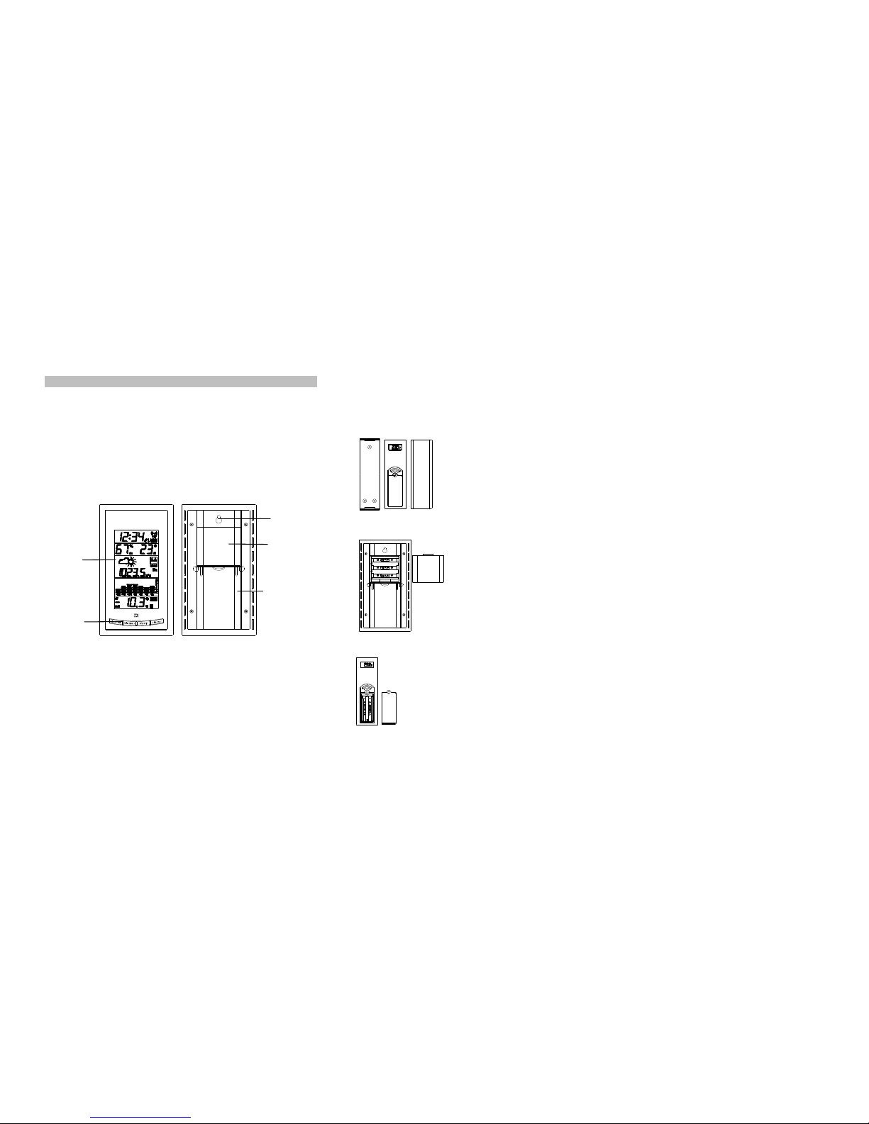
1. First, insertthe batteries into the Weather Station (see “How to install and replace
batteries in the Weather Station”above).Once the batteries are in place, all
segments of the LCD will lightup briefly and a short signal tone will sound. Then the
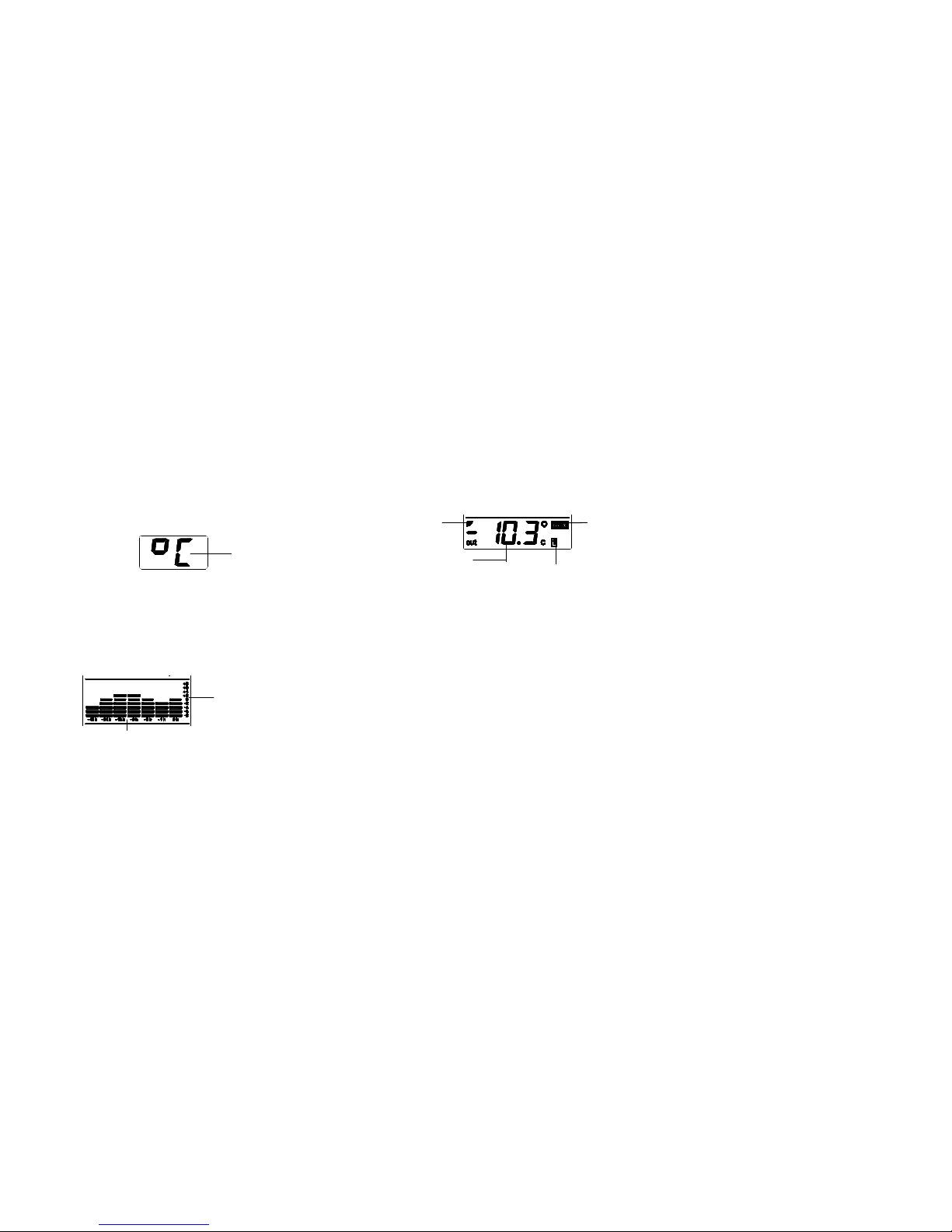
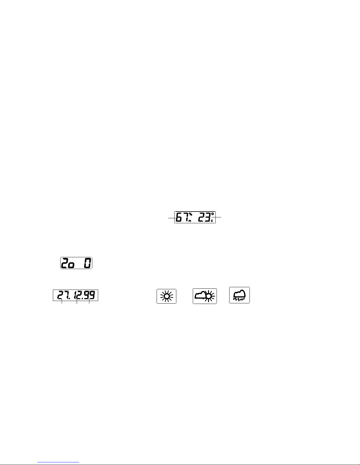
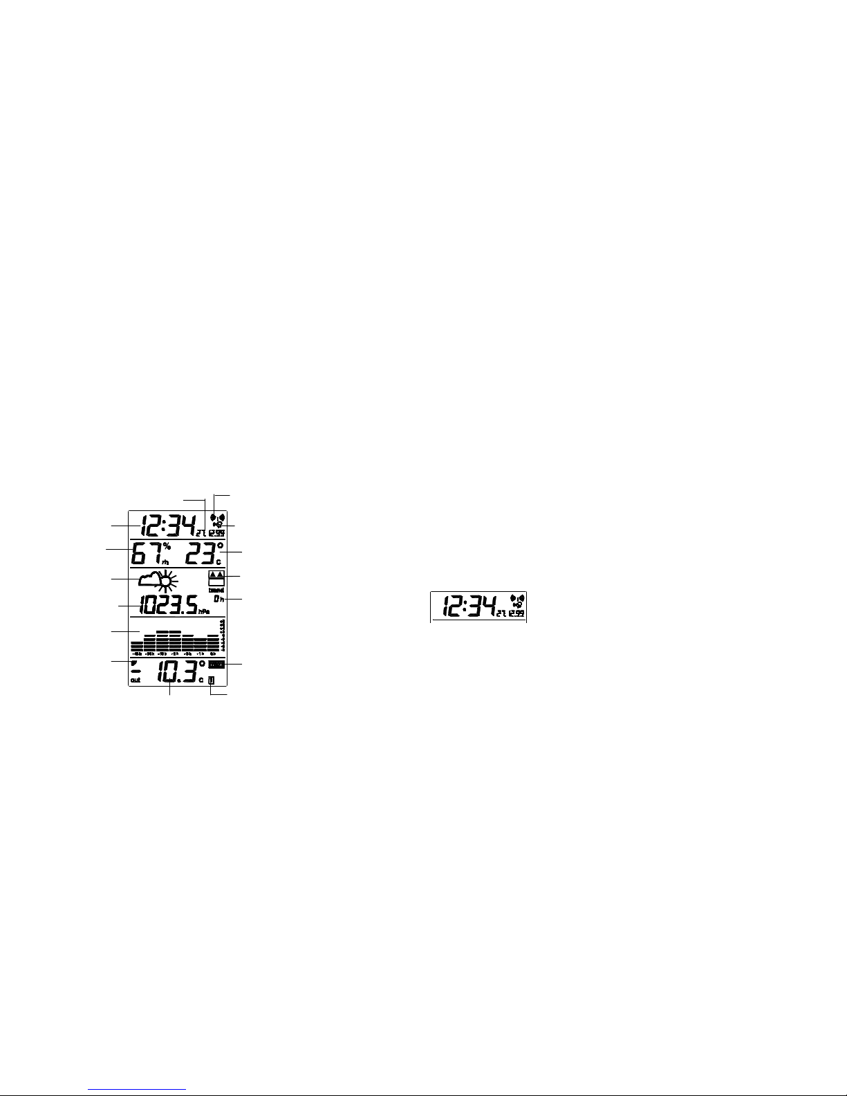
indoor temperature and humidity,the time as 0:00, the dateas 1.1.99 and the
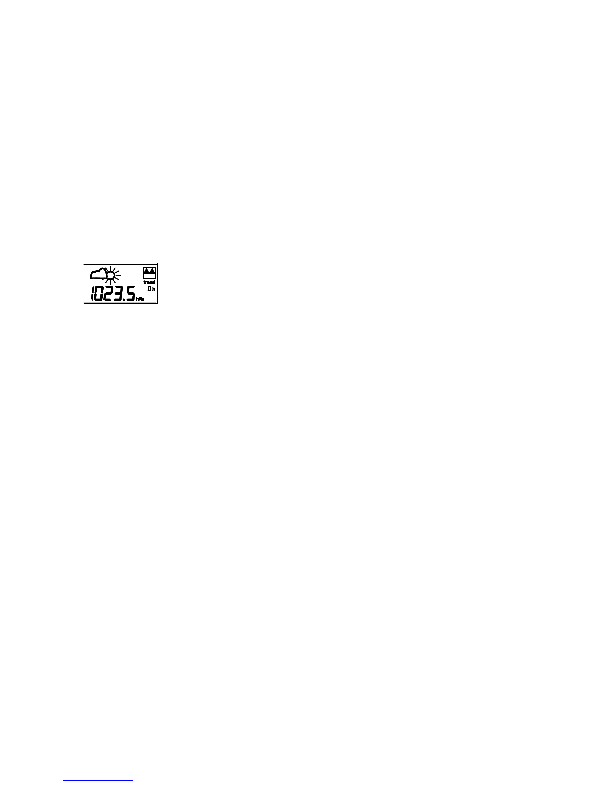
weather icons sun and clouds will be displayed. If the indoor temperature and indoor
humidityare not displayed after a few seconds,remove the batteriesand wait for at
least 10 seconds before reinserting them. Once the indoor data is displayed proceed
to step 2.
2. Within 2 minutes and 30 secondsof activating the Weather Station, place the
batteries into the transmitter (see “Howto install and replace batteries inthe
Outdoor Temperature transmitter“above).
3. After inserting the batteries into the transmitter, the Weather Station will start
receiving data from the transmitter.The outdoor temperature should then be
displayed on the Weather Station. Ifthis does not happen after 2 minutes and 30
seconds,the batteries will need to be removed from both units and reset from step 1.
4. The Weather Station can receive up to3 remote Outdoor Temperature transmitters.If
you have purchased additionaltransmitters,repeat from step 3 for all extra
transmitters. However, ensure that you leave 10 seconds in between the reception of
the last transmitter and the set-up of the following transmitter. The Weather Station
will number the transmitters in the order of set-up, i.e. the firsttransmitter willhave
the temperature displayed with the number 1 againstit and so on.
Note: totalallowed time for setting up of transmitters is2 minutes and 30 seconds from
inserting the batteries into the Weather Station.
5. When all the transmitters are set up, there is a testing period, during which the
reception of all transmittersis checked and the displayswitchesquicklybetween all
the received transmitters at random. Pressing anykeywill stop this process and the
displaywill showthe temperature for the first transmitter. The process also stops
automaticallyif no keys are pressed for 2 minutes and 30 seconds after inserting the
batteries in the Weather Station.
6. Once the outdoor temperature has been received and displayed on the Weather
Station, the DCF-77 time code reception is automaticallystarted. This takes typically
between 3-5 minutes in good conditions.
7. Ifafter 10 minutes, the DCF time has not been received, use the SET keyto manually
enter a time initially.The clock will automaticallyattempt each hour to receive the
DCF time. When DCF reception signal is successful, the received time will override
the manuallyset time.The date is also updated with the received time.(Please refer
also tonotes on “Radio controlled Time Reception” and “Manual Time Setting”).
Note:
In the event of changing batteries in anyof the units, all units need to be reset by
following the setting up procedures. This is because arandom securitycode is assigned
bythe transmitter at start-up and this code must be received and stored bythe Weather
Station in the first 2 minutes and 30 seconds ofpower being supplied to it.
BATTERY CHANGE:
Itis recommended to replace the batteries in all units on an annual basis to ensure
optimum accuracyof these units.
Please participate in the preservation of the environment. Return used
batteries to an authorised depot.
FUNCTION KEYS:
Weather Station:
The Weather Station has4 easyto use function keys and each keyhas twofunctions:
ALARM/SET key
Pressing the keyonce:
•To enter the alarm setting mode
•To stop the alarm during alarm ringing
Pressing the keyfor 3 seconds:
•To enter manual setting mode and each following press for: LCD contrast, time,
time zone, and calendar
MIN/MAX/+ key
Pressing the keyonce:
•To incrementthe alarm time in alarm setting mode
•To incrementthe values in manual setting mode
•To toggle between all MIN and MAX values with time and date recorded
•To stop the alarm during alarm ringing
Pressing the keyfor 3 seconds:
•To reset all indoor values and the selected outdoor values only
-/HISTORYkey
Pressing the keyonce:
•To displaythe relative air pressure figure for the past 0-12 hours
•To stop the alarm during alarm ringing
•To decrement the alarm time in alarm setting mode
•To decrement the values in manual setting mode
Pressing the keyfor 3 seconds:
•To enter the mode for reference air pressure value, and each following press for:
weather forecasting icon sensitivity,and ºC/ºF setting

1
Hanging hole
Battery
compartment
LCD Display
Function
Keys
Folding stand
WIRELESS WEATHER STATION 35.1018
Instruction Manual
INTRODUCTION:
Congratulations on purchasing thisstate-of-the-art Weather Station as an example of
innovative design and qualitypieceof engineering. Providing radio controlled time, indoor
temperature, relative humidity,relativepressure data, and outdoor temperature, this unit
will never keep you guessing on current and future weather conditions. Operation of this
product is simple and straightforward. Byreading this operating manual, the user will
however receive a better understanding ofthe Weather Station together with the optimum
benefit of all its features.
FEATURES:
The Weather Station
•DCF-77 Radio Controlled Clockwith manual setting option
•24 hour time display
•Time zone option ±9 hours
•Alarm setting
•Date,month, year calendar display
•Weather forecasting with 3weather icons
•Weather tendencyindicator
•Storm warning indicator
•Relative air pressure hPa withadjustable reference value
•Relative air pressure historyfor the past 48 hours(electronic barometer with
barometric pressure and trend)
•Indoor temperature reading in °C/ºF with minimum and maximum recording
•Indoor humidityreading displayed as RH% with minimum and maximum recording
•Outdoor temperature reading (for up to 3 transmitters) in °C/ºF with minimum and
maximum and time and date of recording
•Wall mountable or table standing
The OutdoorTemperature Transmitter
•Remote transmission of outdoor temperature to
Weather Station by433 MHz
•Rain proof casing
•Wall mounting case
HOW TO INSTALL AND REPLACE BATTERIES IN THE WEATHER
STATION The Weather Station uses3 x AA, IEC LR6, 1.5V
batteries. When batteries will need to be replaced,
the lowbatterysymbol will appear on the LCD.
To install and replace the batteries, please follow
the steps below:
1. Insert finger or other solid objectin the space
at the bottom center of the battery
compartmentand lift up to remove the cover.
2. Insert batteries observing the correct polarity
(see batterycompartment marking).
3. Replace batterycover.
HOW TO INSTALL AND REPLACE BATTERIES IN THE OUTDOOR
TEMPERATURE TRANSMITTER
The Outdoor Temperature transmitter uses 2 xAAA, IECLR3, 1.5V
batteries. To install and replace the batteries, please followthe steps
below:
1. Remove the batterycover at the front side with a small
screwdriver.
2. Insert the batteries,observing the correct polarity(see battery
compartmentmarking).
3. Replace the batterycover on the unit.
Table of contents
Other Eschenbach Weather Station manuals
Popular Weather Station manuals by other brands

La Crosse Technology
La Crosse Technology KCombo3 WS-9080U-IT WS-9640U-IT manual

La Crosse Technology
La Crosse Technology The Weather Channel WS-8500TWC-IT instruction manual

Delta-T
Delta-T WS-GP1 quick start guide

HomeMatic
HomeMatic HM-WDC7000 operating manual

Bresser
Bresser 7002530 instruction manual

Alecto
Alecto WS-4700 user guide