eschmann SES2000 User manual

SES2000
A UT O CLAVE
Service Manual
ST-SM8l
699215
Service Manual
Introduction
Description
Maintenance
Illustrated parts list
Read these Instructions before use
Keep these instructions in a safe convenient place for future reference. Read in conjunction
with the Publications detailed in Section 1.5.
This Service Manual applies to the following Autoclave REF numbers. (Note: In the parts list
section reference is also made to parts required for earlier versions) :-
SES 2000 STANDARD (from Serial Number - SCB8B0000, or SED8B0000 for non-CE)
without printer : 87-028-04 87-028-20 87-028-36 87-029-05 87-029-13 87-029-21
87-029-37 87-029-45 87-029-54 87-029-62 87-029-70 87-029-78
87-029-86 87-030-03 87-030-11 87-030-27 87-030-43 87-030-60
87-031-03 87-031-68
with printer : 87-028-12 87-028-28 87-028-44 87-029-26 87-030-65 87-031-11
87-031-76
SES 2000 LONG (from Serial Number - LSCB8B0000, or LSED8B0000 for non-CE)
without printer : 87-028-53 87-028-69 87-028-85 87-028-90 87-028-97 87-029-29
87-029-94 87-030-70 87-031-19 87-031-84 87-020-05 87-022-01
87-022-17 87-020-21 87-022-49 87-022-66
with printer : 87-028-61 87-028-77 87-030-75 87-031-27 87-031-92 87-020-13
87-022-09 87-022-25 87-020-29 87-022-58 87-022-74
(Note: The alpha parts of the SN are significant.)
Eschmann After Sales Service Department
The Eschmann After Sales Service Department is staffed and equipped to provide advice and
assistance during normal office hours.To avoid delays when making enquires, please quote the
Model and Serial Number of your Autoclave. Please ensure you include all alpha and numeric
digits of the Serial Number. (NOTE:The Serial Number Plate is located inside the door in the top
left hand corner).
For further information visit www.eschmann.co.uk
All correspondence relating to the after sales service of Eschmann Equipment to be addressed to :
UK Customers
Eschmann Equipment, Peter Road, Lancing,West Sussex BN15 8TJ, England.
Tel: +44 (0) 1903 765040. Fax: +44 (0) 1903 875711.
Overseas Customers
Contact your local distributor. In case of doubt contact Eschmann Equipment.
Patents and Trade marks
The ESCHMANN name and logo are trade marks of Eschmann Holdings Limited.
“Eschmann Equipment” is a trading name of Eschmann Holdings Limited.
“SES2000” is a trade mark of Eschmann Holdings Limited.
Patents : Patents Pending plus - Pat. US5090033 and Pat. GB2238407
Copyright © 2008 Eschmann Holdings Limited
All rights reserved. This booklet is protected by copyright. No part of it may be reproduced, stored in a
retrieval system or transmitted in any form or by any means, electronic, mechanical, photocopying,
recording or otherwise without written permission from Eschmann Holdings Limited.
The information in this publication was correct at the time of going to print. The Company, however,
reserves the right to modify or improve the equipment referred to.
The CE marking affixed to the product certifies that it complies with the
European Medical Devices Directive 93/42/EEC and related legislation.
ST-SM8l November 2008

ST-SM8l Page 3 of 43
SES 2000 AUTOCLAVE
CONTENTS
Page
Contents .. .. .. .. .. .. .. .. 3
Technical data .. .. .. .. .. .. .. 4
PART 1 INTRODUCTION
General .. .. .. .. .. .. .. .. 6
Associated publication .. .. .. .. .. 6
Servicing .. .. .. .. .. .. .. .. 6
PART 2 DESCRIPTION
General .. .. .. .. .. .. .. .. 7
Operating features .. .. .. .. .. .. 7
Operation cycle .. .. .. .. .. .. 9
Operation .. .. .. .. .. .. .. 9
Display messages .. .. .. .. .. .. 10
Error indication .. .. .. .. .. .. 11
General .. .. .. .. .. .. .. 11
Overheating .. .. .. .. .. .. 11
PART 3 MAINTENANCE
Fuses .. .. .. .. .. .. .. .. 15
Fault diagnosis and table .. .. .. .. 15
Parts replacement and adjustment .. .. 20
Removing cover .. .. .. .. .. .. 20
Refitting cover .. .. .. .. .. .. 20
Thermal fuse .. .. .. .. .. .. 20
Transformer.. .. .. .. .. .. .. 20
Controller board .. .. .. .. .. .. 20
Pressure door lock .. .. .. .. .. 20
Air valve .. .. .. .. .. .. .. 21
Door interlock switch .. .. .. .. .. 21
Solenoid door lock (CE only) .. .. .. 22
Heater cycling thermostat .. .. .. .. 22
Temperature sensors .. .. .. .. .. 22
Fill and Discharge valves .. .. .. .. 22
Solid state relay (Non-CE) .. .. .. 22
Solid state relay (CE only) .. .. .. 23
Mechanical relay (CE only) .. .. .. 23
Heating element .. .. .. .. .. .. 23
Printer interface board .. .. .. .. 23
Voltage regulators .. .. .. .. .. 23
Door seal .. .. .. .. .. .. .. 23
Pressure gauge .. .. .. .. .. .. 23
Discharge line filter .. .. .. .. .. 24
Printer .. .. .. .. .. .. .. 24
Special operating modes .. .. .. .. 24
Demonstration mode .. .. .. .. .. 24
Engineering mode .. .. .. .. .. 24
Set-up mode .. .. .. .. .. .. 25
Switch identities and function .. .. .. 25
Power-on modes .. .. .. .. .. 25
Page
Set-up procedure .. .. .. .. .. 26
Autoclave without printer .. .. .. 26
Autoclave with printer .. .. .. .. 26
Setting the Autoclave Serial Number 26
Entering the Autoclave Serial Number 27
Entering the date and time.. .. .. 27
Errors and error clearing .. .. .. .. 28
General .. .. .. .. .. .. .. 28
Control sensor selection .. .. .. .. 28
Autocheck .. .. .. .. .. .. .. 28
Routine Autoclave Calibration .. .. .. 28
General .. .. .. .. .. .. .. 28
Calibration procedure .. .. .. .. 29
Safety valve .. .. .. .. .. .. .. 29
Operational test .. .. .. .. .. .. 30
PART 4 ILLUSTRATED PARTS LISTS
Pipes and fittings, latest models .. .. .. 30
Illustrated parts list 1: Pipes and valves .. 31
Illustrated parts list 2: General spares .. 33
Illustrated parts list 3:
Heater and process controls .. .. .. .. 35
ILLUSTRATIONS
Fig. 1 SES 2000 Autoclave .. .. .. .. 6
Fig. 2 Autoclave General Arrangement .. 12
Fig. 3 Autoclave: Pipes and Valves .. .. 13
Fig. 4 Autoclave: Heater & Process Controls 14
Fig. 5 Door interlock microswitch .. .. 21
Fig. 6 Filter unit disassembly .. .. .. 24
Fig. 7 Switch identities and function .. .. 25
Fig. 8 Autoclave Controller boards .. .. 30
Fig. 9 Pipes and valves .. .. .. .. 32
Fig. 10 General spares .. .. .. .. .. 34
Fig. 11 Heater and process controls .. .. 36
Fig. A1-A5 Autoclave printer details .. .. 40
TABLE
Fault Diagnosis table .. .. .. .. .. 15
APPENDIX A
Autoclave printer .. .. .. .. .. .. 39
APPENDIX B
Schematic - Pipes and Valves .. .. .. 41
APPENDIX C
Schematic - Wiring .. .. .. .. .. 42
Page 4 of 43 ST-SM8l
SES 2000 AUTOCLAVE
TECHNICAL DATA
(Standard Version)
Electrical Data
Supply 220/230/240V a.c. at 50/60Hz
110V a.c. at 50/60Hz
Nominal Loading @ 230V - 2kW (8.7A)
@ 110V - 1.4kW (12.7A)
Fuses Chassis
230/240V 10A, Part No.380003, (x2)
400mA, Part No.696181, (x1)
220V 13A, Part No.380002, (x2)
400mA, Part No.696181, (x1)
110V 16A, Part No.111940, (x2)
800mA, Part No.380004, (x1)
Relay board
T2A, 250V (x1)
Safety standards
IEC 1010-1:1990
IEC 601-1:1977
BS5724:Part 1:1979
ESCHLE (Second Edition 1986)
IEC 601-1-2 (1993)
Sterilizing Data
Sterilizing time
At 134/137°C 3 mins 20 sec.
At 121/124°C 15 mins
Typical overall cycle 134°C : 13 minutes
time (D indicates 134°C : 30 minutes (D)
drying included) 121°C : 24 minutes
121°C : 41 minutes (D)
Note: Overall cycle times may vary depending
on machine and loading conditions.
Nominal Operating pressures:
134°C cycle - 3.14 bar abs
121°C cycle - 2.11 bar abs
Water reservoir
capacity 2.0 litres
Dimensions
Autoclave Width 460mm
Length 461mm
Height 360mm
Chamber Diameter 200mm
Length 348mm (max)
Capacity 10.6 litres
Trays Width 183mm
Length 282.6mm
Height l7mm
Tray Loading 1.5 kg per tray
Weight (approx.)
Net 27.5kg
Shipping 32.0kg
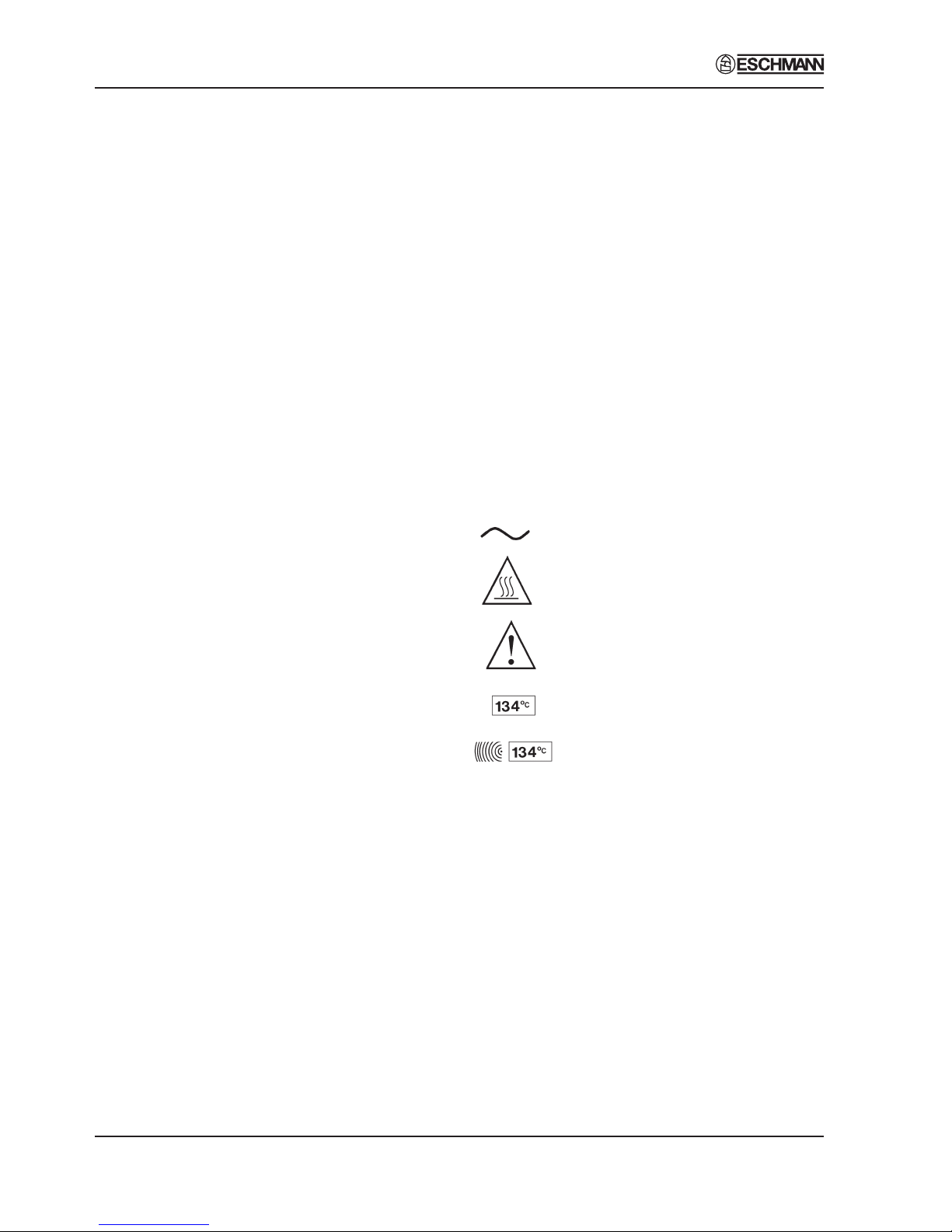
Symbols
For use with alternating current
Caution Hot Surface
Caution refer to accompanying
documents
Sterilising cycle without drying phase
(NB. temperature = cycle temperature)
Sterilising cycle with drying phase
(NB. temperature = cycle temperature)

ST-SM8l Page 5 of 43
SES 2000 AUTOCLAVE
Electrical Data
Supply 230Vac at 50/60Hz
Nominal Loading @ 230V - 2.75kW (12A)
Fuses Chassis
15A, 250V, (x2) Part No. 301871
400mA, Part No. 696181
Relay board
T2A, 250V (x1)
Safety standards
IEC1010-1 (1990)
IEC 601-1-2 (1993)
Sterilizing Data
Sterilizing time
At 134/137°C 3 mins 20 sec.
At 121/124°C 15 mins
Typical overall cycle 134°C : 13 minutes
time (D indicates 134°C : 30 minutes (D)
drying included) 121°C : 24 minutes
121°C : 41 minutes (D)
Note: Overall cycle times may vary depending
on machine and loading conditions.
Nominal Operating pressures:
134°C cycle - 3.14 bar abs
121°C cycle - 2.11 bar abs
Water reservoir
capacity 2.0 litres
Dimensions
Autoclave Width 460mm
Length 650mm*
Height 360mm
* Feet spaced to fit 600mm worktop
Chamber Diameter 200mm
Length 500mm (max)
Capacity 15.6 litres
Trays Width 180mm
Length 457mm
Height 24mm
Tray Loading 3.0 kg per tray
Weight (approx.)
Net 35.5kg
Shipping 40kg
Symbols
For use with alternating current
Caution Hot Surface
Caution refer to accompanying
documents
Sterilising cycle without drying phase
(NB.temperature = cycle temperature)
Sterilising cycle with drying phase
(NB.temperature = cycle temperature)
TECHNICAL DATA
(Long Version)
Other manuals for SES2000
1
Table of contents


