eschmann SES2000 User manual

SES2000 VAC(LS3)
VACUUM AUTOCLAVE
Service Manual
ST-SM45g
110258

Serial Number
Plate
This Service Manual applies to the followingAutoclaves:-
Note: The ‘E’ in the serial number below is the ‘modification state’ of the autoclave and is used
within this manual to identify availability of spare parts where some items on early models are
no longer available.
SES 2000 Vac (LS3) - Standard, from Serial Number SVE1A0000
without printer - REF 87-050-06
with printer - REF 87-050-14
SES 2000 Vac (LS3) - Long, from Serial Number SLVE1A0000
without printer - REF 87-050-22
with printer - REF 87-050-30
Service manual
Read these Instructions before use
Keep this ‘Service Manual’ in a safe convenient place for future reference. Read in
conjunction with the Publication detailed in Part 1.
Eschmann After Sales Service Department
The Eschmann After Sales Service Department is staffed and equipped to provide advice and
assistance during normal office hours. To avoid delays when making enquiries, please quote the
Model and Serial Number of your Autoclave which is shown on the Serial Number plate, the
location of which is shown below. Please ensure you include all alpha and numeric digits of the
Serial Number.
For further information visit www.eschmann.co.uk
All correspondence relating to the after sales service of Eschmann Equipment to be addressed to :
UK Customers
Eschmann Equipment, Peter Road, Lancing, West Sussex BN15 8TJ, England.
Tel: +44 (0) 1903 765040. Fax: +44 (0) 1903 875711.
Overseas Customers
Contact your local distributor. In case of doubt contact Eschmann Equipment.
Patents and Trade marks
The ESCHMANN logo is a registered trade mark of Eschmann Holdings Ltd.
“SES200” is a trade mark of Eschmann Holdings Ltd.
Patents : Patents Pending plus - Pat. US5090033 and Pat. GB2238407
Copyright © 2004 Eschmann Holdings Limited
All rights reserved. This booklet is protected by copyright. No part of it may be reproduced, stored in a
retrieval system or transmitted in any form or by any means, electronic, mechanical, photocopying,
recording or otherwise without written permission from Eschmann Holdings Limited.
The information in this publication was correct at the time of going to print. The Company, however,
reserves the right to modify or improve the equipment referred to.
The CE marking affixed to the product certifies that it complies with the
European Medical Devices Directive 93/42/EEC and related legislation.
ST-SM45g January 2005
Introduction
Description
Maintenance
Illustrated
Parts list

ST-SM45g Page 3 of 53
SES 2000 Vac (LS3) AUTOCLAVE
CONTENTS
Page
Contents .. .. .. .. .. .. .. .. 3
Technical data .. .. .. .. .. .. .. 4
PART 1 INTRODUCTION
General .. .. .. .. .. .. .. .. 6
Associated publications .. .. .. .. .. 6
Servicing .. .. .. .. .. .. .. .. 6
PART 2 DESCRIPTION
General .. .. .. .. .. .. .. .. 7
Operating features .. .. .. .. .. .. 7
Operation cycle .. .. .. .. .. .. .. 9
Display messages .. .. .. .. .. .. 11
Error indication .. .. .. .. .. .. .. 11
General.. .. .. .. .. .. .. .. 11
Overheating .. .. .. .. .. .. .. 12
PART 3 MAINTENANCE
Fuses .. .. .. .. .. .. .. .. 17
Fault diagnosis .. .. .. .. .. .. .. 17
Parts replacement and adjustment .. .. .. 23
Autoclave cover .. .. .. .. .. .. 23
Reservoir assembly .. .. .. .. .. 23
Transformer .. .. .. .. .. .. .. 23
Control board .. .. .. .. .. .. 24
Pressure door lock .. .. .. .. .. 24
Steam bleed solenoid valve .. .. .. .. 24
Door interlock microswitch .. .. .. .. 24
Solenoid door lock.. .. .. .. .. .. 25
Temperature sensors .. .. .. .. .. 25
Solenoid valves
Vacuum, steam bleed, water discharge .. 25
Air-Inlet Solenoid Valve Assembly .. .. 25
Water-Fill Solenoid Valve Assembly .. .. 26
Heatingelement .. .. .. .. .. .. 26
Door seal .. .. .. .. .. .. .. 26
Vacuum pump .. .. .. .. .. .. 26
Condenser .. .. .. .. .. .. .. 27
Cooling Fans.. .. .. .. .. .. .. 27
Bacterial air filter .. .. .. .. .. .. 27
Discharge line filter .. .. .. .. .. 27
Pressure transducer .. .. .. .. .. 27
Solid-state relay board .. .. .. .. .. 27
EMC board .. .. .. .. .. .. .. 28
Printer .. .. .. .. .. .. .. .. 28
Safety Valve .. .. .. .. .. .. .. 28
Band heater Temp. Sensor .. .. .. .. 28
Power switch .. .. .. .. .. .. 28
Float switch .. .. .. .. .. .. .. 28
Cooling ducts .. .. .. .. .. .. 28
Band heater .. .. .. .. .. .. .. 28
Chamber water level sensor .. .. .. .. 28
Manual reset cut-out .. .. .. .. .. 29
Reservoir water filter .. .. .. .. .. 29
Vacuum pump maintenance .. .. .. .. 29
Page
Display board .. .. .. .. .. .. .. 30
Special operating modes .. .. .. .. .. 30
Engineering mode.. .. .. .. .. .. 30
Machine Set-up mode .. .. .. .. .. 30
Set-up procedure .. .. .. .. .. .. 30
Setting the autoclave serial number .. 31
Setting the cycles in use.. .. .. .. 32
Setting the display language .. .. .. 32
Setting date and time .. .. .. .. 32
Setting cycle counter .. .. .. .. 32
Errors and error clearing .. .. .. .. .. 32
Leak test procedure .. .. .. .. .. .. 33
Autoclave Calibration .. .. .. .. .. .. 33
General.. .. .. .. .. .. .. .. 33
Calibrationprocedure .. .. .. .. .. 33
Pressure relief valve test .. .. .. .. 35
Band heater calibration .. .. .. .. .. 36
Functional test .. .. .. .. .. .. 36
PART 4 ILLUSTRATED PARTS LISTS
Illustrated parts list 1: General spares .. .. 41
Illustrated parts list 2: Pipes and valves .. .. 44
Illustrated parts list 3: Heater
and process controls .. .. .. 46
ILLUSTRATIONS
Fig.1 SES 2000 Vac (LS3) autoclave .. .. .. 6
Fig.2.1aAutoclave door handle .. .. .. .. 10
Fig.2.1bAutoclave control panel.. .. .. .. 10
Fig.2.2Autoclave: general arrangement .. .. 13
Fig.2.3Autoclave: pipes and valves .. .. .. 14
Fig.2.4Autoclave: heater and process controls .. 15
Fig.2.5 Sterilizing system schematic diagram .. 16
Fig.3.1 Door interlock microswitch .. .. .. 37
Fig.3.2 Discharge line filter.. .. .. .. .. 37
Fig.3.3 Control panel and switch identities .. .. 37
Fig.3.4 Control board adjustments .. .. .. 37
Fig.3.5 System circuit diagram .. .. .. .. 38
Fig.3.6 Piston vacuum pump .. .. .. .. 40
Fig.3.7 Replacement kit for piston pump .. .. 40
TABLE
Error code table .. .. .. .. .. .. .. 12
Fault Diagnosis table .. .. .. .. .. .. 17
APPENDIX A
Autoclave printer .. .. .. .. .. .. 50
Fig.A1-Fig.A4Autoclave printer .. .. .. .. 51
APPENDIX B
PCA424138 and RelayAssembly 112507
modification November 2004 .. .. .. .. 52
APPENDIX C
New fittings for EMC board .. .. .. .. 53

Page 4 of 53 ST-SM45g
SES 2000 Vac (LS3) AUTOCLAVE
TECHNICAL DATA
(Standard Version)
Electrical Data
Supply 230Vac at 50/60Hz
NominalLoading @ 230V - 2kW (8.7A)
Fuses Chassis
F10A, 250V, (x2)
Part No. 380003
Relay board
F5A, 250V (x1)
T2A, 250V (x1, was x 2 see Parts List 3)
T3.15A, 250V (x1)
Safety standards
EN61010-1:1993
EN61010-2-041:1996
Sterilizing Data (for software version 4.xx or later)
Sterilizing time
At 134/137°C 3 mins 15 sec.
At 121/124°C 15 mins
Typical overall cycle 134°C Unwrapped:
time (D indicates 20 minutes
drying included) 134°C Unwrapped:
35 minutes (D)
134°C Wrapped:
53 minutes (D)
134°C Porous:
63 minutes (D)
121°C Unwrapped:
28 minutes
121°C Unwrapped:
42 minutes (D)
121°C Wrapped:
62 minutes (D)
121°C Porous:
70 minutes (D)
Note: Overall cycle times may vary depending on
machine and loading conditions.
Nominal Operating pressures:
134°C cycle - 3.14 bar abs
121°C cycle - 2.11 bar abs
Water reservoir
capacity 3.5 litres
Dimensions
Autoclave Width 460mm
Length 650mm*
Height 360mm
* Feet spaced to fit 600mm worktop
Chamber Diameter 200mm
Length 348mm (max)
Porous Load Width 156mm (max)
basket Length 280mm
Height 93mm
Trays Width 183mm
Length 282.6mm
Height l7mm
Tray Loading 1.5 kg per tray
Chamber capacity 10.6 litres
Weight (approx.)
Net 45.7kg
Shipping 50.0kg
Symbols
For use with alternating current
Caution Hot Surface
Caution refer to
accompanying documents
"Porous load + Dry" cycle
"Wrapped + Dry" cycle
"Unwrapped+Dry" cycle
"Unwrapped" cycle

ST-SM45g Page 5 of 53
SES 2000 Vac (LS3) AUTOCLAVE
Electrical Data
Supply 230Vac at 50/60Hz
NominalLoading @ 230V - 2.75kW (12A)
Fuses Chassis
15A, 250V, (x2)
Part No. 301871
Relay board
F5A, 250V (x1)
T2A, 250V (x1, was x 2 see Parts List 3)
T3.15A, 250V (x1)
Safety standards
EN61010-1:1993
EN61010-2-041:1996
Sterilizing Data
Sterilizing time
At 134/137°C 3 mins 15 sec.
At 121/124°C 15 mins
Typical overall cycle 134°C Unwrapped:
time (D indicates 15 minutes
drying included) 134°C Unwrapped:
31 minutes (D)
134°C Wrapped:
46 minutes (D)
134°C Porous:
56 minutes (D)
121°C Unwrapped:
26 minutes
121°C Unwrapped:
41 minutes (D)
121°C Wrapped:
57 minutes (D)
121°C Porous:
67 minutes (D)
Note: Overall cycle times may vary depending on
machine and loading conditions.
Nominal Operating pressures:
134°C cycle - 3.14 bar abs
121°C cycle - 2.11 bar abs
Water reservoir
capacity 3.5 litres
Dimensions
Autoclave Width 460mm
Length 650mm*
Height 360mm
* Feet spaced to fit 600mm worktop
Chamber Diameter 200mm
Length 500mm (max)
Porous Load Width 156mm (max)
basket Length 450mm
Height 80mm
Trays Width 180mm
Length 450mm
Height 23mm
Tray Loading 3.5 kg per tray
Chamber capacity 15.6 litres
Weight (approx.)
Net 52kg
Shipping 58kg
Symbols
For use with alternating current
Caution Hot Surface
Caution refer to
accompanying documents
"Porous load + Dry" cycle
"Wrapped + Dry" cycle
"Unwrapped+Dry" cycle
"Unwrapped" cycle
TECHNICAL DATA
(Long Version)

Page 6 of 53 ST-SM45g
SES 2000 Vac (LS3) AUTOCLAVE
GENERAL (Fig. 1)
1 This Manual contains descriptive, maintenance
andsparepartsinformationfortheSES2000Vac (LS3)
autoclave units only.
2 The autoclave is a portable, electrically operated
steamunitdesignedforsterilizing wrapped, unwrapped
orporousloads. Adryingphaseisincluded intheporous
andwrappedcycles,whichisoptionalforanunwrapped
cycle.
3 Wrapped loads must be packed single-wrapped
in L.M.G. SMITH BROTHERS “VIEW-PACK SELF
SEAL” pouches, and sterilized using the special pouch
rack accessory. The autoclave will also take cassettes
using a cassette carrier. A wire basket is provided for
sterilizing porous loads.
4 Theautoclaveoperatesautomatically atthetouch
of a single programme selector touch button, and has
eight sterilization programmes.
5 The autoclave is available with short or long
chambers and with or without an integral printer for
recording details of the sterilizing cycle. Details of the
printer are given inAppendix Apage 50.
ASSOCIATED PUBLICATIONS
6 Separate installation and user instructions are
givenintheSES2000Vac (LS3) autoclave ‘Instructions
for Use’, ST-IM62.
SERVICING
WARNING
When replacing parts during maintenance
procedures ONLY use parts supplied by
Eschmann Equipment or the safety of the
autoclave may be affected.
7 Ensure that routine servicing is carried out at
regular intervals by either Eschmann trained personnel
orsuitablytrained engineersonly,otherwisethewarranty
could be infringed.
8 Keep the Instructions for Use and this Service
Manual readily accessible for reference purposes prior
to and during operation, cleaning and servicing of the
autoclave.
CAUTION
In common with other systems containing static
water reservoirs, water used in this unit can become
contaminated over a period of time, or following an
aborted cycle, and should be treated as a potential
risk of infection.
Note: When sterilizing lubricated dental handpieces,
the reservoir water should be changed every week to
preventcontaminationofthedoor seal, and otherrubber
components, used in the pressure system.
9 Eschmann recommend filling the reservoir with
‘SterileWaterforIrrigation’.Thisislow indissolvedsolids
andhasalowmicrobialcount.IntheU.K.theDepartment
ofHealthrecommendthat ‘Sterile Water for Irrigation’is
used in bench-topAutoclaves (NHS Estates document
HTM2031).
If ‘Sterile Water for Irrigation’ is not being used then
Eschmannstronglyrecommendtheuseofeitherdistilled
water, deionized water, purified water or water treated
by the reverse osmosis process. These types of water
are low in dissolved solids and can help reduce the
effects of tap water detailed below.
DO NOT USE TAP WATER, this is high in dissolved
solidsandcandepositlime scale, blockfiltersandcause
damage to the pressure vessel.
Eschmannalsorecommendthatthereservoirisdrained,
allowed to dry and is refilled on a weekly basis, with the
typeofwaterdetailed in‘a’(or‘b’)above.Ateveryservice
intervalthe reservoir must be removed, be thoroughly
cleaned and dried, and then refilled. This will reduce
thebuild-upofcontaminantsin the waterthatmaycause
blocked filters and/or damage to the pressure vessel.
YourlocalHealthAuthority may suggestthatyouchange
the reservoir water more frequently. Eschmann advise
you to follow your local Health Authority’s
recommendations (also see PART 3, MAINTENANCE
para. 5 to 7).
PART 1 INTRODUCTION
Fig. 1 SES 2000 Vac (LS3) autoclave
Part 1

SES 2000 Vac (LS3) AUTOCLAVE Part 2
ST-SM45g Page 7 of 53
PART 2 DESCRIPTION
GENERAL(Fig.1.1)
1 The autoclave is a portable steam unit heated by
electric elements. For sterilization of porous loads, a
vacuum is created in the chamber. The unit is supplied
tosuitthemainselectricalsupplyshowninTECHNICAL
DATA (pages 4 and 5).
2 The autoclave is electronically controlled and has
eightsterilizingprogrammes:
❑134°CPorousloadwithdrying
❑134°CWrappedloadwithdrying
❑134°CUnwrappedloadwithdrying
❑134°CUnwrappedload
❑121°CPorousloadwithdrying
❑121°CWrappedloadwithdrying
❑121°CUnwrappedloadwithdrying
❑121°CUnwrappedload
Fortypicalsterilizationcycletimes,refertoTECHNICAL
DATA.
3 Therequiredsterilizingprogramme is selectedand
startedbypressingtheappropriateprogrammebuttonon
thefrontpaneloftheunit,followingwhich,thesterilizing/
dryingcycleproceedsautomaticallyuntilcomplete. The
printer(iffitted)willstartautomaticallywhentheprogramme
button is pressed.
4 Indication of cycle status or error codes during a
cycleareprovidedbyadigitaldisplayandprinter(iffitted).
OPERATING FEATURES (Figs. 2.1, 2.2, 2.3 & 2.4)
5 The following equipment, designed for control or
protection, is incorporated in the autoclave:
❑Process Display Window (Fig. 2.2, item 1). The
digitaldisplayindicatesthetemperatureandpressure
insidethechamber. Italsoprovidessimplemessages
for the user which indicate the stages through the
cycle,andalso error conditions, should any occur.
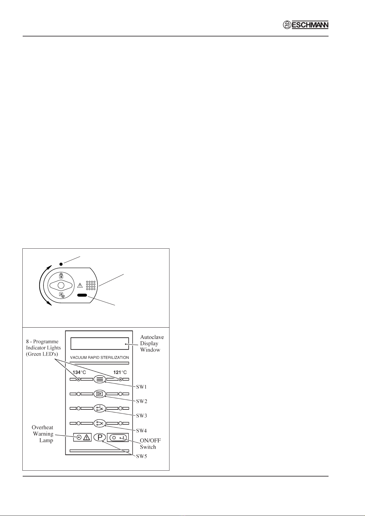
❑FourProgrammeSelectorButtons(Fig.2.1b,SW1
to SW4). These are used to select and start
particularcycles. Theycan alsobeusedtoput the
autoclave in the ‘Engineering’ mode as described
later.
❑Green Light Emitting Diodes (LED’s) (Fig. 2.1b).
There are eight LED’s which flash primarily to
indicate the cycles available for selection that can
bestartedand,whenthishasbeendone,toindicate
the particular cycle which is in progress.
❑Power On/Off Switch (Fig. 2.1b). This switch
controls the mains power supply to the autoclave.
❑OverheatWarningLamp(Fig.2.1b). Illuminationof
this lamp indicates that one of the two protective
overheatcut-outshasoperated.
❑DoorLatchingHandle(Fig.2.2,item3). Thishandle
operatesthedoormechanismtosecurethedoorin
the locked position against the chamber face.
❑Door Safety Latch (Fig. 2.2, item 5). Engages a
safety catch to ensure that the door does not fly
openshouldthereberesidualpressureinthechamber
when the door latching handle is operated. It can
alsobeusedtokeepthedoorslightlyajarwhenthe
autoclave is not in use.
❑Door Interlock Microswitch (Fig. 2.4, item 4). This
is used to signal the controller that the door is
properlyclosed. Itisoperatedbyasimple,adjustable
mechanism and should operate just as the door is
fully closed.
❑Pressure Door Lock (Fig. 2.3, item 14). This is a
safety device designed to ensure that the door
cannotbeopenediftheinternalchamberpressure
exceeds approximately 0.2 bar (3.0 lbf/in2). The
devicecomprisesaspring-loadedplungerdrivenby
thechamberpressureviaarubberdiaphragm.
❑Chamber Pressure Safety Indicator (Fig. 2.1a).
Fittedadjacenttothedoorlatching handle(Fig.2.2
item 3) and operated by the pressure door lock
(Fig.2.3 item 14), it indicates that the chamber is
pressurised(red)andit isunsafetoopenthedoor,
or unpressurised (green) and it is safe to open the
door.
❑Solenoid Door Lock (Fig. 2.4, item 12). The
solenoiddoorlockpreventsthedoorbeingopened
bytheoperatoroncethecyclehasstarted. Thelock
holds the door closed until the sterilizing cycle is
complete. Itwillalsokeepthedoorclosedunderall
fault conditions. As absence of power is also a
‘fault’ the unit power switch must be set to ‘on’ in
ordertoopenthedoor.
Note: Itisnecessarytooverridetheelectricaldoor
lock to clear an error code. This is done by setting
thepowerswitchto ‘off’,then,afterafew seconds,
setting it back to ‘on’ again while pressing and
holdingthe‘P’selector(SW5)onthefrontpanel(Fig
2.1b).
❑WaterReservoir(Fig.2.2,item16). Thisisusedto
holddistilledordeionizedwaterorwatertreatedby
reverseosmosiswhichisadmittedintothechamber
via the water fill valve. The water reservoir also
receives hot water and steam vapour discharged
fromthechambertowards theendofthecycle, via
the discharge valve. The vacuum pump (Fig. 2.3,
item 7) also discharges into the water reservoir.

Part 2 SES 2000 Vac (LS3) AUTOCLAVE
Page 8 of 53 ST-SM45g
PART 2 DESCRIPTION
❑Water Filter. The water filter is fitted on the end of
the water fill pipe in the water reservoir, and filters
thewaterenteringthechamber.
❑ReservoirFloatSwitch(Fig.2.3,item11). Thewater
reservoir is fitted with a float switch which will stop
the cycle being started if there is insufficient water
in the reservoir to complete a chamber fill. ‘Fill
Reservoir’ will be displayed should this occur.
❑Heating Element (Fig. 2.4, item 1). The heating
element consists of a single immersion element
insidethechamber.Theheatingelementiscontrolled
byasolidstaterelayandprotectedfromoverheating
byamanualreset thermostat.RefertoTECHNICAL
DATAforheaterelementloading.
❑Solid-State Relay Board (Fig. 2.4, item 14). See
AppendixB. Thereareanumberof keyfunctions
providedbytherelay board:
wSolid state relays (SSR) control the mains
supplytothewaterheaterelement(10A),band
heater(10A)andvacuumpump(2A).
wSSR status LEDs, give an indication of drive
status (On/Off).
wMechanical relay provides additional safety
for heater and pump circuits.
wFusesforprotectingthe20Va.c.supply(3.15A),
condenser fan (2A) and vacuum pump (5A)
see 'Parts List 3'.
wTwovoltageregulators.
wAutoclavebleeper.
wConnections for mains loom, signal loom,
temperature and pressure sensors, solenoid
valves,andtransformer.
wInterface for front panel, control board, and
printer.
❑ManualResetOverheat Cutout(Fig.2.4,item21).
Themanualresetoverheatcutoutisfittedattherear
oftheunitandisconnectedinserieswiththepower
supply switch, band heater overheat cutout,
mechanicalandSSrelayandheater element. The
manualresetoverheatcutoutisoperatedbyafluid-
filled capsule clamped to the heating element,
providingprotectionifthetemperature oftheheater
surfaceexceeds250°C.Itwillremakeelectricallyif
theresetbuttonattherearofthecabinetispressed,
after giving the heater element time to cool.
❑Band Heater Overheat Cutout (Fig. 2.4, item 24).
Thebandheatercutoutisfittedontheband heater
and is connected in series with the power supply
switch,ManualResetOverheatCutout,mechanical
and SS relay and Band Heater. It contains a bi-
metallic disc thermostat which operates if the
temperatureoftheheatersurfaceexceeds 250°C.
Thecutoutwillremakeelectricallyiftheresetbutton
is pressed when the heater has cooled.
❑Fuses. The unit has five fuses:
wTwo fuses (Fig. 2.4, item 2) on the rear panel
ofthecabinetratedasshowninTECHNICAL
DATA, which are connected in the ‘mains
supply’ to the unit.
wThreemorefuses are fitted on the solid-state
relayboard(seeTECHNICALDATA).
❑Transformer (Fig. 2.4, item 17). The transformer
convertstheincomingmainsvoltageto24Va.c. It
is rated at 50VA.
❑Water Fill Solenoid Valve (Fig. 2.3, item 4). The
waterfillvalvecontrolsthewaterfillsequence. Itis
electrically operated from the 24V d.c. supply
generatedandsignalledfromtheSSRboard.
❑WaterDischargeSolenoidValve(Fig. 2.3, item3).
Thewaterdischargevalveisusedattheendofthe
sterilizing cycle to allow water and steam vapour
from the chamber to pass back into the reservoir.
The valve is electrically operated from a 24V d.c.
supplygeneratedandsignalledfromtheSSRboard.
❑Discharge Line Filter (Fig. 2.3, item 12). Prevents
debris from the chamber entering and fouling the
waterdischargevalve.
❑SteamBleedSolenoidValve(Fig.2.3,item2). The
steambleedsolenoidvalveoperatesinconjunction
with the steam bleed valve.
❑Steam Bleed Valve (Fig. 2.3, item 15). The steam
bleed valve is connected in series with the steam
bleedsolenoidvalvetobleedsteamfromthechamber
during the 121°C cycles. It contains a ball and
spring which allows air displaced by the steam
generatedinthechambertopassintothereservoir.
Once steam starts to pass, the ball then lifts and
seals. A small ‘bleed’ remains, however, and it is
quitenormalforsmallquantitiesofsteamtoescape
into the reservoir throughout the cycle.
❑Safety Valve (Fig. 2.3, item 16). The safety valve
isfittedonthechambertee-pieceattherearofthe
chamber,andisfactorysettoreleasepressurefrom
withinthechamber. Itisaprimarysafetydeviceand
must not be readjusted.
❑AirInSolenoidValve(Fig.2.3,item5). Theairinlet
valve controls the admission of bacteriologically
filteredairto thechamberduringthedryingphase.
Anon-returnvalvepreventsflowfromthechamber
to the bacterial filter to keep it dry.
❑Vacuum Solenoid Valve (Fig. 2.3, item 1). When
open,thisvalveallowsthevacuumpumptosuckair
and steam from the chamber.

SES 2000 Vac (LS3) AUTOCLAVE Part 2
ST-SM45g Page 9 of 53
PART 2 DESCRIPTION
❑VacuumPump(Fig.2.3,item7). Thevacuumpump
isatwostagediaphragmpumpusedtosuckairand
steamfromthechamber.Somemodelswerefitted
withapistonpump(seeFig.3.6)whichisnolonger
available,incaseoffault,replaceitwiththecurrent
diaphragmpump.
❑Condenser (Fig. 2.3, item 6). The condenser pre-
cools air and steam from the chamber before it
enters the vacuum pump.
❑BacterialFilter(Fig.2.3,item10). Thebacterialfilter
filters the air entering the chamber.
❑ChamberTemperatureSensors(Fig.2.4,item16).
Theseareusedtosensethechambertemperature
andarefittedattherearofthechamber. Onesensor
controlsthetemperaturewithinthechamberandthe
other controls the displayed and the printed
temperatures.
❑Band Heater Temperature Sensor (Fig. 2.4, item
15). Thebandheatertemperaturesensorisusedto
control the band temperature during the drying
phase.
❑ThermocoupleEntryPort(Fig.2.4,item23). Thisis
used to insert a thermocouple into the chamber to
allow the operating temperature to be measured
and, if necessary, adjusted.
❑PressureTestPort(Fig.2.4,item22). Thepressure
test port is used to insert a pressure measuring
probetomonitorthechamberpressure.
❑ControlBoard(Fig.2.4,item19). Thecontrolboard
interfaceswiththerelayboardandfrontpanelboard
to control every aspect of management of the
autoclave. The main features are:
wTwomicrocontrollers(U1andU12Idents.onPCB)
whichreceiveinformationfromthefrontpaneland
allthesensors(temperature(3off),pressure,door
interlock,chamberwaterlevel,reservoirlevel). If
any errors are detected they are shown on the
display, and printed (if a printer is fitted) as error
codes(see Part 2, para. 28 and29).
wMessage memory (U13) in four variants
covering all the main languages spoken by
Eschmanncustomers.
wTrimmer potentiometers for calibration of the
band heater and temperature/pressure
channels.
wEngineering switch for set-up and calibration
modes(seespecialoperatingmodespage30).
wOutputs from the control board control the
heaters, pump, and solenoid valves via the
relayboardinterface.
❑Front Panel Board (Fig. 2.4, item 13). This board
incorporates the vacuum fluorescent display,
programme select and cancel switches, and
programme indicator LEDs. It interfaces with the
control and relay boards via a 10-way ribbon
connector.
❑PressureTransducer(Fig.2.4,item7). Thepressure
transducer monitors the pressure in the chamber
andgenerateschamberpressuresignalsforcycle
monitoring,control,anddisplay.
❑Printer(Fig.2.2,item21). Theprinter,iffitted,starts
automatically when a cycle button is selected and
will print out a hardcopy of the sterilization cycle.
DetailsoftheprinteraregiveninAppendixAtothis
Manual.
❑Fans(Fig.2.4,items10and11). Twofansarefitted
in the autoclave. One fan provides cooling for the
condenserandthePCB compartment (via a bleed
conduit). Theotherfandrawsairoverthechamber
for rapid cooling between cycles.
❑Band Heater (Fig. 2.4, item 18). The band heater
heats the chamber during the drying cycle.
❑EMC Board (Fig. 2.4, item 5). The EMC board
provideselectro-magneticcompatibility protection
for the autoclave.
OPERATIONCYCLE
6 Adetailedknowledgeoftheoperationoftheautoclave
is not necessary to be able to repair it effectively;
however,abasicunderstandingofthevariousprocesses
ofautoclaveoperationwhichoccurduringacycleisgiven
inthefollowingparagraphs.
CAUTION
EnsurethattheAutoclaveis switchedoffbefore
filling the reservoir. DO NOT USE TAP WATER.
Note:Whenfillingthereservoir,consultthe'Instructions
forUse'whichprovidesinformationonthetypesofwater
that should be used.
7 Powerisswitchedonbyselectingthepowerswitch
(O-I)toI(Fig.2.1b). Ifthechamberdoorisopentherenow
followsasingleaudibletoneaccompaniedbythedisplay
'SES Vacuum LS3+cycle count+version of software',
whichthenchangesto'CLOSE THEDOOR'.
8 Ifthedoorisclosed,whenpowerisswitchedon,the
displaywillshow'SESVacuumLS3+cyclecount+version
ofsoftware',whichthenchangesto'OPENTHEDOOR'.
9 After the work trays have been put in the chamber
and the door closed, a programme can be selected and
initiated by pressing one of the programme selector
buttons (Fig. 2.1b). If the autoclave has a printer it will
automaticallystartwhentheprogrammeselectorbutton
is pressed.
Part 2 SES 2000 Vac (LS3) AUTOCLAVE
Page 10 of 53 ST-SM45g
PART 2 DESCRIPTION
10 Whenthedoorisclosed,withthepowerswitchedon,
thisis sensed by the controlboardviathedoor interlock
switch. Ifanyattemptismadetoopenthedooroncethe
cyclehasbegun,thedisplay'ERROR2'will appear and
anaudiblesignalwillsound. Underthesecircumstances
itisnecessarytoswitchtheautoclaveoff,wait5seconds,
resettheerror(seePart3,para.54)andrestartthecycle.
11 Theautoclaveoperatesautomaticallyatthetouchof
asingleprogrammeselectortouchbutton(Fig.2.1b),and
haseightprogrammes:
❑134°CPorousloadwithdrying(SW1)
❑134°CWrappedloadwithdrying(SW2)
❑134°CUnwrappedloadwithdrying(SW3)
❑134°CUnwrappedload(SW4)
❑121°CPorousloadwithdrying(SW1)
❑121°CWrappedloadwithdrying(SW2)
❑121°CUnwrappedloadwithdrying(SW3)
❑121°CUnwrappedload(SW4)
12 Eachprogrammeselectorbuttononthecontrolpanel
(Fig. 2.1b) will select either the 134°C or 121°C cycles.
The programme indicator lights, at each side of the
programme selector buttons, will change to indicate a
changeofselectionbetween134°Cand121°Ceachtime
the appropriate selector button is pressed. In addition,
the display will show the appropriate programme
description to confirm the programme that has been
selected. Once the programme and the temperature
rangehasbeen selected,thesterilizationcyclewill start
automatically,afteradelayofapproximatelyfourseconds.
13 The printer, if fitted, will start printing and, as the
cycleprogresses,variousdisplaymessageswillappear
inthedisplaywindowtoindicatethe programme status.
Note: Ifaprogrammeisstartedinerror,itcanbecancelled
bypressingthe'P'selectorbutton(SW5),providedthatthe
cycle has not reached the water fill stage.
14 When a cycle is selected (SW1- SW4 pressed),
'CYCLE STARTED'willbedisplayed,quicklyfollowedby
'VACUUM ON', indicating that the vacuum pump has
started, and the vacuum solenoid valve has opened to
evacuate the air from the chamber.
15 Whenthepressureinthechamberhasdecreasedto
therequiredvaluefortheprogrammeselected,thewater
fillvalvewillopenand'FILLING'willbedisplayed,indicating
thatwaterisbeingsuckedfromthereservoirandintothe
chamber.
16 When the cycle has started, the door cannot be
openedduetotheelectricdoorlockandvacuumforceon
thedoor.
17 When the correct quantity of water has entered the
chamber, the water fill valve closes together with the
vacuum valve. The heater, controlled by the control
board,willswitchon,andthepressureinthechamberwill
increase. This phase is indicated by 'PULSING' being
shown on the display.
18 Theheateriscontrolledbyasystemwhichensures
that the operating temperature is reached with minimal
overshoot. Initially, the heater will be 'on' continuously
andthemeasured temperature will be displayed. Note,
however,thatthesystemdoesnotregistertemperatures
below92°C.
19 Temperatures are displayed with a resolution of
0.1°C,using signalaveragingtoensureastable,accurate
display.
20 Controlofthecycleisfullyautomaticwithtemperature
information being monitored by temperature sensors.
Timingiscontrolledbythecontrolboardandcycletimes
cannotbeadjusted. Bycomparingmeasuredvalueswith
knowntime/temperaturerelationships,thecontrolboard
is able to detect faults such as lack of water at the fill
stage,orlossofwaterandsteamduringtheprocess,and
Fig. 2.1b Autoclave control panel
Fig. 2.1a Autoclave door handle
Locked
Unlocked
Safety catch
behind door plate
Door lock position
indicator
Chamber pressure
indicator

SES 2000 Vac (LS3) AUTOCLAVE Part 2
ST-SM45g Page 11 of 53
PART 2 DESCRIPTION
itwillindicatesuchproblemsbydisplayingerrorscodes
suchas'ERROR3'or'ERROR4'respectively,whichwill
beaccompaniedbyanaudiblewarningsignal(seeError
CodeTablepage12).
21 The autoclave operates at temperatures slightly
abovethe usualrecommendedminimums.Theoperating
temperatureforthe121°Ccycleissetto122°C,andthe
134°C cycle is set for 135°C.
22 As the cycle enters the sterilization phase, the
displayshows'STERILIZING'. Attheendofthesterilizing
phasetheheateristurnedoffandthedischargevalveis
openedtodischargewaterandsteamfromthechamber.
Thisphaseisindicatedby'CONDENSING'beingshown
on the display.
23 Oncethecontrollerdetectsthatchambertemperature
and pressure have fallen to a safe level, the display
'CYCLE COMPLETE' will be shown to indicate that the
cycleiscomplete. Whenthechamberdoorisopenedthe
displaywillshow'CLOSETHEDOOR'.
Note: If the autoclave has a printer, the printout will
includethefollowing details:
❑Autoclavetype and serial number.
❑Date and time of sterilization cycle.
❑Counterindication(five digits with leading zeros).
❑Sterilization cycle type, e.g. 134°C without drying.
❑Sterilizationcycletime,temperature,andpressure.
❑Sterilization cycle ended message.
Operating information relating to the printer is given in
Appendix A to this Manual.
24 The overall time for the cycle is not fixed and
dependsonmanyfactorssuchasthesupplyvoltage,the
load,andtheambienttemperature. However,thecontrol
board will ensure a satisfactory sterilization cycle even
when these factors vary over wide ranges.
25 If a cycle employing a drying phase is selected,
operationtotheendofthesterilizingphaseisasdescribed
previously. Afterdischargeofsteamandwaterbackinto
the reservoir, however, the display 'DRYING' will be
indicated,togetherwiththetimeremainingtotheendof
the cycle. During the drying phase, operation of the
autoclave will alternate between vacuum pulses and
filtered air inlet pulses to achieve optimum drying.
26 Thelengthofthedryingphasewillvaryaccordingto
theprogrammeselected,andthechamberbandheater
will operate to promote drying. At the end of the drying
phase, the display 'CYCLE COMPLETE' will appear
indicatingthat the door can be opened.
DISPLAY MESSAGES
27 Throughout a selected cycle the following symbols
may appear on the digital display:
Display Meaning
OPENTHEDOOR Door was closed when the
autoclavewasswitched'on'.
PLEASE WAIT* The autoclave is measuring
atmosphericpressure
CLOSETHEDOOR Thedooris openandthecycle
cannot start.
READY FOR USE Waitingprogrammeselection.
CYCLESTARTED Programmeselectedandcycle
started.
VACUUMON Chamber air/steam discharge
inprogress.
FILLING Waterenteringchamberpriorto
steriliszation
PULSING Pre-sterilization steam
treatment.
STERILIZING Sterilizationinprogress.
CONDENSING Discharging water and steam
fromchamber.
DRYING Loadbeingdried(timeremaining
to the end of cycle will also be
shown).
CYCLECOMPLETE Cycle completedsuccessfully.
* Only applicable to software version 5.2 or above (as
shownbrieflyondisplaywhenautoclavefirstswitchedon).
ERRORINDICATION
General
28 Ifanerroroccursduringthecycle,an errorcodewill
bedisplayed(seetheErrorCodeTable on page 12).
29 Ifanerroroccursduringacycle,thecontrolboardwill
cancel the cycle (see Fault Diagnosis, and Errors and
ErrorClearingin Part3).
Note: Theseerrorcodeswillgenerallyrequireinvestigation
by an Eschmann trained engineer. If an error occurs
duringthecycle,theprinter(iffitted)willprintoutthedate
andtime,themessage'CYCLEFAILED'andtheappropriate
error code. Information relating to the printer, if fitted, is
given in Appendix A to this Manual.

Part 2 SES 2000 Vac (LS3) AUTOCLAVE
Page 12 of 53 ST-SM45g
PART 2 DESCRIPTION
ERRORCODETABLE
Display Meaning/Cause
POWERFAILURE Temporaryfailureinthe
(Error1notshown) mains supply to the unit.
Error2 Faulty or incorrectly adjusted
door switch, or door not fully
closed at start of cycle.
Error3 Water failed to enter chamber
fromreservoir.
Error4 Water level in chamber has
dropped during run-up to
sterilizing cycle.
Error5 Heater element not working
duringrun-uptosterilizingphase.
Error6 Controlchannellowtemperature.
Error7 Control channel high
temperature.
Error8 Display channel low
temperature.
Error9 Display channel high
temperature.
Error10 Insufficient first vacuum pulse.
Error11 Insufficient second vacuum
pulse.
Error12 No steam pulse.
Error13 (i) Before filling takes place
= Air Detector test failure
(ii)Atbeginningofsterilization=
Steamqualityerror.
Error14 Insufficient drying vacuum.
Error15 Sensor system failure.
Error16 Clock speed error during
sterilizingphase.
Error17 Band heater not achieving
setpoint temperature during
dryingphase.
FILLRESERVOIR Water level in reservoir has
droppedbelow'MIN'mark.
Overheating
30 Intheunlikelyeventofoverheating,theredoverheat
warning lamp (see Fig. 2.1b and Fig. 2.4 item 8 ) at the
frontoftheautoclavewillilluminate. Ifthishappens,first
allow10to15minutestoelapsefortheautoclavetocool,
then check the water level in the reservoir and top-up if
required. When the water level is correct, press the
'PRESSTORESET'buttonattherearofthecabinet(Fig.
2.4 item 21) and restart the cycle as normal. If the fault
persists,switchoff the autoclave and call an Eschmann
TrainedEngineer.
SES 2000 Vac (LS3) AUTOCLAVE Part 2
ST-SM45g Page 13 of 53
PART 2 DESCRIPTION
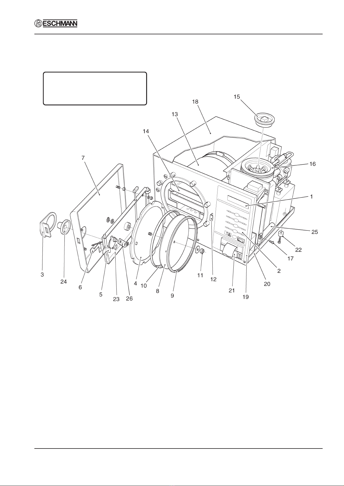
1 Processdisplaywindow 10 Sealretainingrim 19 Frontpanel
2 Controlpanel 11 Aerotightnut 20 Chassis
3 Doorlatchinghandle 12 Door safety catch 21 Printer
4 Pressuredoor 13 Pressurechamberassembly 22 Foot
5 Doorlatch 14 Worktray 23 Doorbeam
6 Pressure safety indicator 15 Reservoirlid 24 Doorknob
7 Doorcover 16 Reservoir 25 PCBcoolingconduit
8 Seal retaining disc 17 Coverscrew 26 Link
9 Doorseal 18 Unit cover
Fig.2.2 Autoclave:GeneralArrangement
Note: Some autoclaves will have a
different pump to that shown. See
maintenance section and parts list for
pumpreplacementdetails.

Part 2 SES 2000 Vac (LS3) AUTOCLAVE
Page 14 of 53 ST-SM45g
PART 2 DESCRIPTION
'A' - Stud coupling nut
1 Vacuum valve 9 Transducercoil
2 Steam bleedsolenoidvalve 10 Bacterial air filter
3 Waterdischargevalve 11 Reservoir float switch
4 Water fill valve 12 Dischargeline filter
5 Air in valve 13 Non-returnvalve
6 Condenser 14 Pressure doorlock
7 Vacuumpump 15 Steam bleed valve
8 Pump foot 16 Safety valve
Fig. 2.3 Autoclave: Pipes and Valves
Note:Someautoclaveswill
have a different pump to
that shown. See
maintenance section and
parts list for pump
replacementdetails.

SES 2000 Vac (LS3) AUTOCLAVE Part 2
ST-SM45g Page 15 of 53
PART 2 DESCRIPTION
1 Heatingelement 9 ON/OFF (O/I) switch 17 Transformer
2 Mains fuses 10 Enclosurefan 18 Bandheater
3 Mains cable 11 Condenserfan 19 Controlboard
4 Microswitch 12 Solenoiddoorlock 20 Printer
5 EMCboard 13 Frontpanelboard 21 Manualresetoverheatcut-out
6 Choke 14 Solid-staterelayboard* 22 Pressure test port
7 Pressuretransducer 15 Bandheatertemperaturesensor 23 Thermocoupleentryport
8 Overheatwarninglamp 16 Chambertemperaturesensors 24 Bandheateroverheatcut-out
25 Bulb(forManualReset21)
* see Appendix B
Fig. 2.4 Autoclave: Heater and Process Controls
Note: Some autoclaves will have a
different pump to that shown. See
maintenance section and parts list for
pumpreplacementdetails.

Part 2 SES 2000 Vac (LS3) AUTOCLAVE
Page 16 of 53 ST-SM45g
PART 2 DESCRIPTION
Fig. 2.5 Sterilizing System Schematic Diagram

SES 2000 Vac (LS3) AUTOCLAVE Part 3
ST-SM45g Page 17 of 53
PART 3 MAINTENANCE
FUSES (Fig. 2.4 )
1 The autoclave is protected by five fuses. Two mains supply fuses are fitted on the rear cover of the autoclave
(Fig.2.4item2). Threemorefusesarefittedtothesolidstaterelayboard(Fig.2.4.item14). Allfuseratingsaregiven
in the TECHNICAL DATA section.
FAULTDIAGNOSIS
2 Anumberoftypicalfaultswhichcouldoccur,theirpossiblecausesandhowtoremedythemarelistedbelow.For
maintenanceproceduresrefertoPartsReplacementandAdjustment.
Note: Cross references in the ‘Remedy’ column (e.g. para.10) refer to paragraphs in the Parts Replacement and
Adjustment section that follow later in Part 3.
WARNINGS
Switch-offanddisconnectmains power supplybeforeremovingthe autoclave cover,ordoing
maintenanceprocedures.Duringcertainprocedures mainsvoltagemay haveto bepresentwith the
cover removed and extreme care should be taken to avoid contact with mains voltage.
Checkthatchamber isatatmospheric pressurebeforeopening thedoor.
Should the door be opened beware of possible very hot water or steam escaping from the chamber.
FaultDiagnosisTable
Fault PossibleCause Remedy
(1) Nothinghappenswhenpower (a) Mains supply failure. (a) Check mains supply, also
switchedon(Nodisplay). plugand supply cable
forlooseconnections
orbreaks.
(b) Mainfusesblown (b) Replacefuse(s)*.
(rearpanel).
(c) Faulty power switch. (c) Replacepowerswitch
(para31).
(d) Solid-staterelayboard (d) Replacefuse*.
fuse blown or loose.
(e) Transformerfailed. (e) Checktransformersecondary
voltage (20V a.c. rms).
Replacetransformerif
output is zero (para 8).
(f) Short circuit on (f) Check sensor, fill valve, vent
24V circuit. valve etc. for short circuit
Replacewherenecessary.
(g) Short circuit on solid-state (g) Check SSR board is correctly
relayboard. fitted in bottom guide,
withcorrectclearancefrom
dividingpanel. Also see
AppendixB
*Note: Blown fuses can indicate further problems. Always investigate the reason for any fuse blowing,
but bear in mind that fuses can ‘age’ and blow for no other reason.
Continued

Part 3 SES 2000 Vac (LS3) AUTOCLAVE
Page 18 of 53 ST-SM45g
PART 3 MAINTENANCE
Fault PossibleCause Remedy
(2) Doorcannotbeopened. (a) Pressuredoorlockjammed. (a) Replacepressuredoorlock
(para.10). Toopenchamber
door,pushpressurelocking
bolt back with a thin blade
if spring faulty. If spring has
seized, disconnect body from
unit(para.10)andpullit
backwards so that the locking
bolt clears the door.
(b) Pressureinchamber. (b) Switch-onpowertorelease
pressureinchamber.
(c) Vacuum inchamber. (c) As (b) to open door then
check discharge filter and
bacteriologicalfilterfor
blockage.
(d) Solenoiddoorlock (d) Checkwiringtosolenoiddoor
inoperativewhenautoclave lock and check solenoid for
power is switched on. shorting or open circuit.
Replace solenoid door lock if
necessary(para.13).
(3) Chamber will not fill (a) Nowater inreservoir. (a) Fillreservoir.
(FILLRESERVOIRdisplayed). (b) Water in float switch. (b) Fit new float switch (para.32).
(4) Display shows ERROR3. (a) No waterinchamberdueto (a) Clean or fit new water filter
water fill valve or associated (para.37).Strippipework
pipes or filter blocked. and clean. Empty and clean
reservoir. Refill with
distilledwater(para.9part1).
(b) Sensornotdetectingwater (b) Ensurechamberwaterlevel
inchamber. sensor is clear of obstructions
Also, ensure sensor is not
dirtyorcorroded.
(5) Display still shows (a) Doorinterlock (a) Checkswitchoperating
‘OPENTHEDOOR’ microswitchjammed lever forfreedomof
afterdooris opened. in closed position. movement.
(b) Switch fault. (b) Check operation of switch.
(c) Doorinterlock (c) Adjust switch lever position,
microswitch out or fit new microswitch if
of adjustment.
adjustment is correct (para 12).
(6) Display shows‘ERROR2’ (a) Dooropenedafter (a) Switch power off, wait
after cycle started. cycle selected. 5 seconds, reset error (see
para (53) and restart cycle.
(b) Door switch out of (b) Adjust switch lever position,
adjustment. or fit new microswitch
(para12).
Continued

SES 2000 Vac (LS3) AUTOCLAVE Part 3
ST-SM45g Page 19 of 53
PART 3 MAINTENANCE
Fault PossibleCause Remedy
(7) Safety valve leaks (See also (a) Dirt on valve seat. (a) Withlowpressureinchamber
Fault(8)). carefullyoperatevalve
byhand(Warning:Beware
of risk of scalds from escap-
ing steam). If leakage per-
sists, fit new safety valve
(para.29).
(b) Checkpressureand (b) Re-calibratecontrolboard
temperature to see if (para.57onwards).
calibration is set too high.
(8) Safety valve operates even (a) Safety valve fault. (a) Fit new safety valve (para.29).
thoughtempisbelow136°C (b) Re-calibrationneeded. (b) SeeCalibrationProcedure
(SeealsoFault(7)). (para.57onwards).
(c) Chambertemperature (c) Fitnewtemperaturesensor
sensor fault. (para.14).
(d) Controlboardfault. (d) Fitnewcontrolboard
(para.9).
(9) Temperatureabove137°C (a) Failed solid state relay. (a) Fit new solid state relay
causing safety valve to board(para.26).Alsosee
operate. AppendixB
(10) ‘ERROR4’displayed (a) Water fill valve leaking. (a) Drainreservoirandfitnew
beforesterilizingtemp. waterfill valve(para.17).
reached. (b) Dischargevalveleaking. (b) Stripandcleanwater
discharge valve or fit a
newone(para.15).
(c) Chamberwaterlevel (c) Fitnewchamberwaterlevel
sensor fault. sensor(para.35)
(d) Wiringloomfault. (d) Checkterminations.
(e) Doorsealleaking. (e) Clean mating surfaceof
gasketarounddoorwitha
soapy cloth. If leakage
persists,replacedoor-
seal(para.19).
(11) ‘ERROR5’displayed. (a) Solid state relay (a) Fitnew relayboard
failed(Novoltage (para.26).Alsosee
acrossheater). AppendixB
(b) Heateropen-circuit. (b) Fit new heater if resistance
of element when cold is not
approx.30ohms(shortauto-
clave)or20ohms(longauto-
clave)(para.18).
(c) Controlboardfault. (c) Fitnewcontrolboard
(para.9).
Continued

Part 3 SES 2000 Vac (LS3) AUTOCLAVE
Page 20 of 53 ST-SM45g
PART 3 MAINTENANCE
Fault PossibleCause Remedy
(12) Temperaturediffersfrom (a) Recalibrationrequired. (a) Recalibrate(para.57onwards).
measuredvalueanddisplay
shows ‘Err 6, 7, 8, or 9’. (b) Chambertemperature (b) Check sensor fitted
sensor fault. correctly, or fit new
sensor(para.14)and
recalibrate(para.57onwards).
(13) No dischargeofsteam/water (a) Discharge valve fault. (a) Testvalve, using‘Engineering
at end of cycle. Mode’(para.40).Replaceif
faulty(para.15).
(b) Wiringfault. (b) Check connections to
dischargevalve.
(c) Blockageindischarge (c) Strippipeworkandclean.
line.
(d) Controlboardfault. (d) Replacecontrolboard
(para.9).
(e) Dischargeline (e) Cleanorreplacefilter
filter blocked. (para.24).
(14) Cycle time much longer (a) Lowmainsvoltage. (a) Check supply to autoclave.
thanusual. (b) Autoclaveoverloaded. (b) Avoidoverloading(seeTray
loadinginTechnicalData
section)
(c) Slowdischargeatend (c) SeeFault (13) (c) and (e).
of cycle.
(d) Faulty vacuum pump. (d) Repair or fit new vacuum
pump(para.20).
(e) Leak in pressure system. (e) Checkandrepair.
(15) Unusualdisplaywhen (a) Controlboardfailedto (a) Switch-off power, wait for
first switching on power. re-setproperly. approx. 5 seconds and switch
onagain.
(b) Controlboardfault. (b) Fitnewcontrolboard
(para.9).
(16) Displayshows (a) Temporarymains (a) Check local supply conditions.
‘POWERFAILURE’. failureduring cycle. (b) Checksupplyplug wiring and
powercableforbreaks.
(c) Carryouterrorcancellation
(para.53)thenremoveload
from chamber. Ensure load is
conditioned(dry)before
restartingappropriatecycle.
Continued
Other manuals for SES2000
1
This manual suits for next models
4
Table of contents
Other eschmann Laboratory Equipment manuals

Popular Laboratory Equipment manuals by other brands


Celestron
Celestron 44422 Quick setup guide

PIKE Technologies
PIKE Technologies GladiATR manual

bioMerieux
bioMerieux Air IDEAL 3P user manual

Sutter Instrument
Sutter Instrument MT-75 Series Assembly instructions

PASCO
PASCO PASCObot Gripper PS-3325 Product guide

Boekel
Boekel Slide Moat 240000 operating instructions

Hettich
Hettich MIKRO 200 operating instructions

Globe Scientific
Globe Scientific GCM-12 quick start guide

Biocomp
Biocomp GRADIENT MASTER 108 operating manual

Cole Parmer
Cole Parmer Stuart SB3/1 instruction manual

Parr Instrument
Parr Instrument 4560 Operating instructions manual

Integra
Integra DOSE IT operating instructions