ESCO Technologies ETS-LINDGREN SuiteSentry Specification sheet

SuiteSentry™ Single Screener
Operation and Installation Manual
September 2018 PNPNPNP Rev A

Page 2 of 34

Page 3 of 34
TABLEOFCONTENTSPAGE
TABLE OF CONTENTS 3
LIST of FIGURES 4
Acronyms used in this manual ..............................................................................................4
Symbols and Terms ...............................................................................................................4
Damage in Transportation .....................................................................................................4
Language Policy – Service Documentation...........................................................................5
1.0INTRODUCTION & OVERVIEW 6
1.1Background...................................................................................................................6
1.2The Current Situation ...................................................................................................6
2.0PRE-INSTALLATION CHECKLIST 7
2.1Product Identification and Shipping List.....................................................................7
2.2Tools Required for Assembly and Installation............................................................7
2.3Summary of Tasks........................................................................................................8
3.0SITE SELECTION & INSTALLATION GUIDELINES 9
3.1Overview .......................................................................................................................9
3.2Functional Siting Requirements-Location...................................................................9
3.3Operational Siting Requirements-Performance........................................................10
3.4Operational Considerations-Usage ...........................................................................10
4.0INSTALLATION, MOUNTING and POWER-UP 11
4.1Installation and Mounting of SuiteSentry Single Screener ......................................11
Reference Documents - Installation Wiring Diagram .........................................................14
4.2Power-Up and Diagnostic Instructions......................................................................18
5.0OPERATION PROCEDURES 19
5.1General Description of Operation of SuiteSentry Single Screener..........................19
5.2Operation and Usage of SuiteSentry Single Screener .............................................20
6.0CALIBRATION & DIAGNOSTIC PROCEDURES 23
6.1Sensitivity Adjustment................................................................................................24
6.2Motion Detector Adjustment ......................................................................................25
7.0ROUTINE MAINTENANCE and SERVICE 26
7.1Cleaning of SuiteSentry Single Screener..................................................................26
7.2Periodic Testing of SuiteSentry Single Screener......................................................26
8.0CUSTOMER SERVICE 26
9.0SPECIFICATIONS, CLASSIFICATION & REFERENCE DOCUMENTS 27
9.1Specifications .............................................................................................................27
9.2Device Classification..................................................................................................27
9.3Reference Documents - Installation Wiring Diagram................................................28
9.4Mounting Dimensions - SuiteSentry Single Screener ..............................................29
10.0 Typical Installation Pictures 30
WARRANTY POLICY 33
Revision Date Author Primary Reason for Change
A September
2018 MS Initial Release

Page 4 of 34
LISTofFIGURES
PAGE
Figure 1: Temporary set up in shipping crate ....................................................................................................12
Figure 2: Connect Power Supply to SuiteSentry Single Screener in Shipping Crate .....................................12
Figure 3: SuiteSentry Single Screener standing – Ready to TEST Location....................................................12
Figure 4: Drill Locations for Mounting Brackets ...............................................................................................14
Figure 5: Typical Installation ...............................................................................................................................14
Figure 6.1, 6.2, 6.3, 6.4 Fastening Wall Toggler to Wall ...................................................................................15
Figure 7: Fastening Wall Toggler through Mounting Block and into wall. ...................................................... 16
Figure 8: Exploded view of Mounting Block, toggle, screw and washer into wall...........................................16
Figure 9: a, b, c, d, Exploded views of Mounting Block+Mtg Block Extension over Rub Rail. ......................16
Figure 10: Fastening Mounting Block to SuiteSentry Single Screener ...........................................................17
Figure 11: Completed Installation.......................................................................................................................17
Figure 12: SuiteSentry Single Screener - 3 Modes of Operation......................................................................20
Figure 13: a., b., c. - SuiteSentry Single Screener Operation and Usage .......................................................22
Figure 14: SuiteSentry Single Screener Controls.............................................................................................23
Figure 15: SuiteSentry Single Screener top cap and PIR access/adjustment.................................................25
Figure 16: Typical Installation .............................................................................................................................28
Acronyms used in this manual
ACR: .........American College of Radiology
TJC: ..........The Joint Commission
Zone II: .....ACR definition of area immediately outside the MRI control room
Zone III: ....ACR definition of area immediately outside the MRI magnet room
Zone IV: ....ACR definition of area inside the MRI magnet room
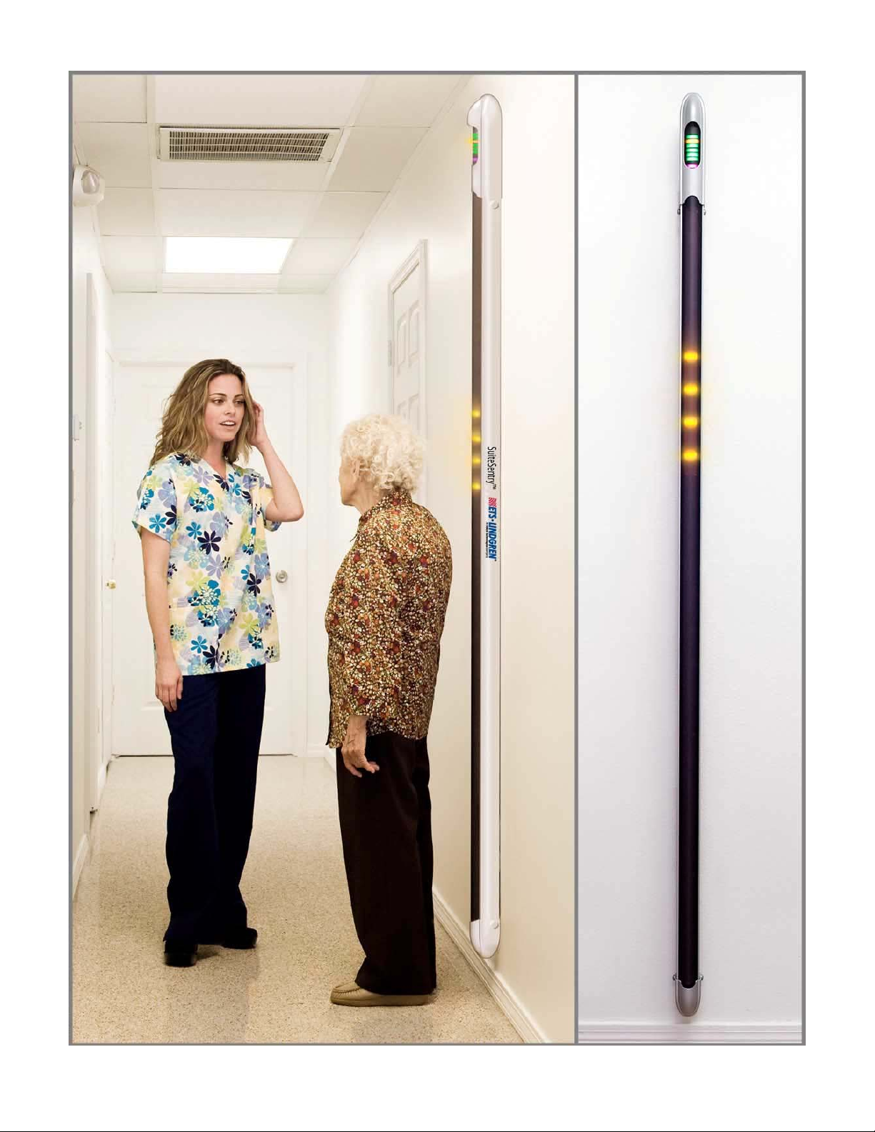
FMD: .........Ferromagnetic Detector
LED: ..........Light Emitting Diode; electronic replacement for lamp
PIR: ...........Passive Infra-Red-Detects body heat and motion and
...................enables SuiteSentry Single Screener to go into Active Mode
Symbols and Terms
NOTE: The following Symbols and Terms may be used in this manual:
Damage in Transportation
All packages should be closely examined at time of delivery. If damage to outer package is visible,
make certain the notation “damaged in shipment” was written on all copies of the freight or express
bill when delivery is accepted by your receiving agent. Whether noted or concealed, damage must
be reported to the carrier immediately upon discovery, or in any event, within 14 days after
receipt, and the contents and containers held for inspection by the carrier. Transportation
company will not pay a claim for damage if an inspection is not requested within this 14 day
period. Transport this product for a period not to exceed 4 weeks. The following environmental
conditions must be adhered to in order to avoid damage to the product.
Ambient Temperature: -34°C (-11°F) to +60°C (+140°F)
Relative Humidity: 15% TO 95% (Non-Condensing)
Atmospheric Pressure: 50 kPa (0.5 atm) to 127 kPa (1.25 atm)
WARNING!
Warning statements identify conditions or practices that could result in injury or death.
CAUTION!
Caution statements identify conditions or practices that could result in damage to the product or
other
p
ro
p
ert
y
.
TIP or HINT:
The following is a recommendation and may help simplfy efforts during the installation.

Page 5 of 34
Language Policy – Service Documentation
WARNING
This Service Manual is available in English only.
If a customer’s service provider requires a language other than English, it is the customer’s responsibility to
provide translation services.
Do not attempt to service the equipment unless this service manual has been consulted and is understood.
Failure to heed this Warning may result in injury to the service provider, operator or patient from electric
shock, mechanical or other hazards.
AVERTISSEMENT
Ce Manuel de maintenance n’est disponible qu’en anglais.
Si le technicien du client a besoin de ce manuel dans une autre langue que l’anglais, c’est au client qu’il
incombe de le faire traduire.
Ne pas tenter d’intervention sur les équipements tant que le manuel Service n’a pas été consulté et compris.
Le non–respect de cet avertissement peut entraîner chez le technicien, l’opérateur ou le patient des blessures
dues à des dangers électriques, mécaniques ou autres.
WARNUNG
Dieses Kundendienst-Handbuch existiert nur in englischer Sprache.
Falls ein fremder Kundendienst eine andere Sprache benötigt, ist es Aufgabe des Kunden für eine
entsprechende Übersetzung zu sorgen.
Versuchen Sie nicht, das Gerät zu reparieren, bevor dieses Kundendienst-Handbuch nicht zu Rate gezogen
und verstanden wurde.
Wird diese Warnung nicht beachtet, so kann es zu Verletzungen des Kundendiensttechnikers, des Bedieners
oder des Patienten durch elektrische Schläge, mechanische oder sonstige Gefahren kommen.
AVISO
Este Manual de Servicio sólo existe en inglés
Si algún proveedor de servicios ajeno a KDI solicita un idioma que no sea el inglés, es responsabilidad del
cliente ofrecer un servicio de traducción.
No se deberá dar servicio técnico al equipo, sin haber consultado y comprendido este manual de servicio.
La no observancia del presente aviso puede dar lugar a que el proveedor de servicios, el operador o el
paciente sufran lesiones provocadas por causas eléctricas, mecánicas o de otra naturaleza.
ATENÇÃO
Este Manual de Assistência Técnica só se encontra disponível em Inglês.
Se qualquer outro serviço de assistência técnica, que não a KDI, solicitar estes manuais noutro idioma, é da
responsabilidade do cliente fornecer os serviços de tradução.
Não tente reparar o equipamento sem ter consultado e compreendido este Manual de Assistência Técnica.
O não cumprimento deste aviso pode por em perigo a segurança do técnico, operador ou paciente devido a‘
choques elétricos, mecânicos ou outros.
AVVERTENZA
Il presente manuale di manutenzione è disponibile soltanto in inglese.
Se un addetto alla manutenzione esterno alla KDI richiede il manuale in una lingua diversa, il cliente è tenuto
a provvedere direttamente alla traduzione.
Si proceda alla manutenzione dell’apparecchiatura solo dopo aver consultato il presente manuale ed averne
compreso il contenuto.
Non tenere conto della presente avvertenza potrebbe far compiere operazioni da cui derivino lesioni
all’addetto alla manutenzione, all’utilizzatore ed al paziente per folgorazione elettrica, per urti meccanici od
altri rischi.

Page 6 of 34
1.0INTRODUCTION&OVERVIEW
SuiteSentry™ Single Screener is a revolutionary patented Ferromagnetic Detector (FMD) system
designed to help keep ferromagnetic material from accidentally entering the Magnetic Resonance
Imaging magnet room. The system primarily consists of an array of sensors and microprocessors
built into a walk-up Sensor Array Column.
This product is intended to reduce the risk from an ordinary object that might suddenly become an
unintended projectile due to its attraction to the magnetic field of the MR scanner magnet.
SuiteSentry Single Screener incorporates the following features:
Accurately and Rapidly Locates Ferromagnetic Hazards Anywhere on the Body
Uniform Sensitivity with Six (6) Sensor Zones placed equidistant in the Sensor Array
Column
No-Touch Activation for the ultimate in convenience and hygiene
Highly Sensitive - Can detect small items down to hairpin size
Used to Self-screen or for Supervised Screening
Variety of Simple Installation Options
1.1 Background
MR Super-Conducting Scanners generate an enormously strong magnetic field, typically 30,000 to
60,000 times the Earth’s magnetic field. Due to the significant technical and economic hurdles in
generating the magnetic field, it is never purposely turned off; it is always in the ‘ON’ condition, 24
hours a day, 7 days a week. This extremely powerful magnetic field, invisible but ever-present,
continuously attracts anything which is ferromagnetic (generally containing iron or steel). It can and
will attract and pull any ferromagnetic object such as hand tools, oxygen bottles, scissors, chairs,
IV stands, and even floor buffers toward the magnet.
1.2 The Current Situation
All personnel who may come in close proximity of the MR scanner, within the four (4) progressively
restricted zones of danger, are supposed to receive training about the risks the MRI magnetic field
presents, what kind of objects contain ferromagnetic material, and therefore the danger of bringing
these materials in close proximity to the magnet. Since the MR static fields is never shut down, this
must include maintenance and security personnel who may come in close proximity during non-
scanning hours.
The patient procedures adopted in operating these MR devices have evolved into a careful pre-
screening of patients to make sure they do not have anything on their person or active/passive
implants in their person, which would be attracted by the very strong magnetic field; and, in the case
of some heart pacemakers or defibrillators, potentially have their function changed by the scanner’s
magnetic field.
Even with training and copious use of warning signs, people forget or are unaware that an object
may contain ferromagnetic material, thereby increasing the risk of a disaster.
Even small ferrous objects pose a risk of injury. A hairpin, for example, can travel at 40 MPH into a
1.5T magnet. Larger objects have injured and even caused fatalities.
Even if no injury occurs, the financial costs from downtime and re-imaging can be very large.

Page 7 of 34
2.0PRE‐INSTALLATIONCHECKLIST
2.1 Product Identification and Shipping List
The SuiteSentry Single Screener hardware is shipped in one corrugated carton. This long carton
contains all the items required for assembly and installation of the SuiteSentry Single Screener
System. The contents are listed below.
Component Qty P/N
SuiteSentry Single Screener - Sensor Array Column Assembly 1 400151
Power Supply - Digital w/ 12’ output cable / connector 1 9910-A-01427-C
AC mains power cord – w/ 90° Plug - 3 ft long -- USA 1 6608-A-01497-A
Installation Hardware Kit - SuiteSentry Single Screener 1 9993-A-02760-A
Surface Conduit Accessory Kit – Ivory – SuiteSentry Single Screener 1 9993-A-02041-B
Document Package – SuiteSentry Single Screener 1 0550-A-02016-D
Spacer, Mounting Block Extension 2 2973-A-02778
Mat, Floor, Solo Instructive 1 0540-A-02050
Box, Return Materials, 14” x 8” x 5” (w/ UPS Return Label) 1 2840-A-02838
2.2 Tools Required for Assembly and Installation
1. #2 Phillips screwdriver 6 inches long (15 cm)
2. Box cutting knife with replacement blades
1. Medium duty electric or battery drill with at least 2 spare charged batteries
2. 1/4 inch nut driver/1/4 inch wrench (ratcheting wrench is best)
3. 3/8 inch nut driver/3/8 inch wrench (ratcheting wrench is best)
4. Drill bit index with at least two (2) 1/8 inch drill bits and ½ inch bit for wall togglers
5. Measuring tape up to 12 feet (4 meters)
6. Micro screwdrivers, flat head and Phillips
7. 6 inch (15 cm) bubble level
8. Heavy Duty PVC cutters for wire trim moldings (Sears 3-1 Accu-Cut Model 37310 recommended)
9. Painter’s tape (for detector) and clear packing tape (for parts return box)

Page 8 of 34
2.3 Summary of Tasks
The following steps are a general guideline and actual workflow may differ depending on the specific
site and installation area. This section is provided so the installer has a general outline of the steps in
the installation and training process.
.
1.
Select and verify the desired mounting location, method of attachment and
location of the power outlet. Always Ask!
(a dedicated outlet might have been put in specifically for the detector)
2.
Select method and routing for Power cables to Sensor Column
3.
Leave Sensor Column in shipping container for next step!
4.
Test Sensor Array Column in desired location before permanent mounting
5.
Mount Sensor Array Column
6.
Adjust final calibration of Sensor Array Column
7.
Mount laminated copy of Short Form Instructions near detector (SAP)
(Only if facility permits, ask first!)
8.
Clean area and remove installation debris
9.
Train the MRI staff and have them sign provided “Training Record” roster
*
10.
Take pictures of installed detector
*
11.
Complete “Quality Assurance Document”
*
12.
Complete ”Installation and Training Acceptance Document”
*
13.
Have responsible party sign all documents and provide copy to signee
*
14.
Send all documents and pictures to ETS-Lindgren
*
(Same day preferred, immediately following installation)
*These items are required for permanent warranty registration file!
Please make detailed notes on each document as they will be added to the device
TIP! Test SuiteSentry Single Screener in desired installation area prior to
permanent mounting to ensure it is viable for that installation location otherwise
you may have to relocate due to electromagnetic interference!!!
HINT: The installer should request that the SuiteSentry Single Screener be
brought to the installation area by the facility staff prior to arrival at the site.

Page 9 of 34
3.0SITESELECTION&INSTALLATIONGUIDELINES
3.1 Overview
The SuiteSentry Single Screener Ferromagnetic Detector consists of an array of sensors and
microprocessors built into a walk-up Sensor Array Column. The detector analyzes objects on
patients or personnel passing in front of the Sensor Array Column, screening for the object’s
potential risk as a ferromagnetic projectile.
If an object made of ferromagnetic material approaches the Sensor Array Column, the system
detects the object’s ferrous content, analyzes its ferromagnetic mass and threat potential; and, if
the mass exceeds the preset sensitivity threshold, an audible alarm is activated and ferrous object
indicator lights is illuminated in the vertical sensor array column of the portal.
Since the device detects only those materials that will be attracted to the magnet, items made of
aluminum, titanium, copper, brass and other non-ferrous materials will not trigger an alarm. Please
note, however, that seemingly non-ferrous materials may have enough ferrous properties to activate
the audible and visual alarms.
The detector only analyzes moving objects containing ferromagnetic material. Stationary
ferromagnetic objects will be ignored.
The SuiteSentry Single Screener is typically installed in Zone 2. The sensitivity should be set to
detect objects reliably without exhibiting “false positives”. The device is intended to detect and
alarm for smaller ferromagnetic objects approximately the size of a typical hair pin or larger when
the object is approximately 12 inches from the Sensor Array Column.
SuiteSentry Single Screener has no detection limitations with regard to locating ferromagnetic
material inside an object or human body. Therefore, if a ferrous non-superficial or subcutaneous
object is detected, further investigation is recommended following your facility’s standard practice.
Even if our product does NOT react, one should NOT automatically assume that there are no
ferromagnetic risks.
3.2 Functional Siting Requirements-Location
In order to ensure the system will provide detection and alert for ferromagnetic objects, the unit
should be positioned so that all equipment, patients, and personnel entering the magnet room have
been screened and can proceed directly to the magnet room. Do not screen patients and then have
them sit in waiting area as they may pick up a ferrous object that they did not possess during the
screening process. The Sensor Array Column should also be positioned to provide the most useful
opportunity for screening patients and staff, if that is your policy or desire.
Summary of Functional Siting Requirements:
The location should have a measured magnetic fringe field of less than 2 Gauss.
The preferred location to install SuiteSentry Single Screener is near the Zone 2 patient
changing area or another location before entry into Zone 3.
Keep detector away from magnet room (Unit CANNOT be above 2 Gauss)
Locate the detector within the area so as not to interfere with patient transport and to prevent
possible damage from patient transport impact.
If location is on wall with bumper rail guards; modify them to accommodate SOLO installation.
TIP! To ensure the unit is functional in the desired area of operation TEST unit
at the desired location PRIOR to permanent mounting!
WARNING!
This device has not yet been fully evaluated for its efficacy in detection of
ferromagnetic objects inside the body, such as IMPLANTS

Page 10 of 34
3.3 Operational Siting Requirements-Performance
Since SuiteSentry Single Screener is designed to detect moving ferrous objects passing near or
approaching the Sensor Array Column, the selected site should be away from extraneous moving
objects such as printers, office chairs, and file cabinet drawers. Special hardware and software
design reduces the sensitivity to moving ferromagnetic objects on the sides and behind the Sensor
Array Column, but separation of movable ferromagnetic masses from the sides of the Detector
System is also desirable.
Maintain separation from electrical devices, especially those which contain transformers, electrical
motors or other moving parts as these devices create magnetic fields which can mimic moving
ferromagnetic objects. Distance should be maintained from electrically locked or electrically
opening doors. Some doors have magnets mounted on them to activate switches used to indicate
that the door is closed. Plan your installation to maintain separation from these doors and devices.
Summary of Operational Siting Requirements:
Remove electrical devices 9 feet (3 meters) away from the installed detector to prevent false
positive alarms.
Ensure area of installation is free from electrical and electromagnetic interference when
possible.
If electronic equipment is within 9 feet (3 meters) the detector may very well exhibit false
positives. Determine the object/device that causes this condition and remove from immediate
vicinity of the detector and allow the detector to stabilize to the environment.
3.4 Operational Considerations-Usage
The highest sensitivity to moving objects occurs within 3 inches of the Sensor Array Column. All
efforts should be made to minimize traffic in the area of the Sensor Array Column during the
screening process as this traffic may have ferromagnetic objects which can cause unintended
alarms.
The change from standby to active mode is determined by adjusting the Passive Infrared (PIR)
motion sensor located in the Top Control Panel display. Even small ferromagnetic objects on a
person or staff member that routinely enter the magnet room may trigger an alarm as these ferrous
objects will be magnetized by exposure to the MRI’s magnetic field. Once magnetized, some small
objects will cause an alarm identical to a larger-in-mass object. To minimize these alarms, staff
should be trained to minimize wearing of ferrous objects; such as, underwire bras, shoes with steel
shanks or springs, belt buckles, pens, badges, eyeglasses, and hair clips.
Summary of Operational Considerations:
Staff wearing ferrous material in their clothing will cause the detector to alarm. REMOVE all
clothing that exhibits alarms to ensure consistent screening results.
The detector will alarm for attire such as watches, belts, shoes, and underwire bras. If you feel
it pull at or near the bore, the detector will alarm on the object within several feet (5’) or more.
The SuiteSentry Single Screener is to be used only as a prescreening device.
All staff should acknowledge the detector alarms and not enter zone III if an alarm is displayed
until offending ferrous object is removed.
CAUTION!
The SuiteSentry Single Screener detector MUST be placed in area that has LESS
than a 2 Gauss field strength. Ensure that it is functionally capable of performing
in the preferred area of operation prior to permanent mounting!

Page 11 of 34
4.0INSTALLATION,MOUNTINGandPOWER‐UP
4.1 Installation and Mounting of SuiteSentry Single Screener
Physical installation is simple and only requires a few basic tools. The key to a successful
installation is to adhere to the recommendations for installation location as set forth in Section 3.
Once the desired mounting location has been determined, and the SuiteSentry Single Screener
prescreening detector has been verified for function in the desired location, the mounting of the
detector can commence. Follow the steps below:
Step One: Set Unit in Trial Location: (Refer to Figures 1, 2 & 3.)
The SuiteSentry Single Screener comes mounted in rigid foam centered inside the cardboard
shipping box. It is meant to remain in the shipping box while still in foam support blocks and can
then be placed as a free standing functional detector to ensure functionality in the area where it is
to be mounted. This allows the installer to easily place and determine IF the detector can be
permanently installed in the desired location. It can easily be moved around as needed to ensure
the area is compatible with the detector.
The shipping carton and foam blocks are designed to support SuiteSentry Single Screener as a
free-standing fixture for initial installation process as well as protect while shipping.
(NOTE: DO NOT LEAVE DETECTOR UNATTENDED – Unit can fall over!)
To prepare SuiteSentry Single Screener from shipping carton, first remove all other equipment
placed inside shipping box. With those items out of the box:
Remove the power supply and power cable from the power supply cover
Plug in the power supply to the SuiteSentry Single Screener (Bottom Cap-Rear) and the line
cord into the outlet -slide SuiteSentry Single Screener away from shipping carton if you need
to plug the supply cable in to the bottom cap receptacle. (SEE Fig. 1, 2 and 3 in Sec.4.1)
After the unit automatically sequences through the self-test routine (approx. 35 seconds), it is
extremely important to monitor the detector and ensure it is STABLE to the electromagnetic fields in
the area. Leave it in this position for at least 5-10 minutes to allow the electronics to normalize to this
location. Very Important: If the blue LED’s at top do not stop illuminating, the detector should
not be mounted in this location! Move the detector away from the area incrementally to find a
stable location for permanent mounting.
If there are moving objects or other electromagnetic interferences too near which cause the blue
bar graph to indicate 1 bar segment or greater, lower the sensitivity or relocate the detector as this
location is not suitable. As gauss fields decrease at the cube of the distance, move the detector
incrementally away to find a more stable installation location. Sensitivity can be decreased from 1
beep (maximum) to 25 beeps (minimum) (factory setting) incrementally decreased to mid-scale if
the location does not allow for maximum sensitivity however the ability to detect smaller objects will
be diminished.
The object(s) causing the disturbance should be moved or the SuiteSentry Single Screener should
be moved to ensure stability.
If the location is acceptable, continue with the permanent installation steps outlined next.
TIP! Fully read Section 3 & Section 4 prior to starting Installation
CAUTION!
The SuiteSentry Single Screener is sensitive to large dynamic EM pulses as well
as strong static gauss fields. If the detector cannot stabilize in the preferred
locaiton a secondary location must be found!

Page 12 of 34
InstallationandMountingofSuiteSentrySingleScreener
(Continued)
F
igure
2
:
Temporary set up in shipping crate
Tilt the bottom end of SuiteSentry
Single Screener out about 1-2 inches to
more easil
y
attach
p
ower in
p
ut
Remove power supply and
main power cable to power up
the detector for operation
verification prior to permanent
mountin
g
.
Rigid Foam Support
Blocks for shipping and
initial installation
p
rocedure
F
igure
3
:
Connect Power Supply to SuiteSentry Single Screener in
Shipping Crate
F
igure
1
:
SuiteSentry Single Screener standing
–
R
eady to TEST Location

Page 13 of 34
Step Two: Remove SuiteSentry Single Snanner from the shipping/test carton:
Remove the SuiteSentry Single Screener and carefully place SuiteSentry Single Screener on
floor/horizontal surface out of the way. Carefully remove rigid foam blocks from body of
SuiteSentry Single Screener column.
Step Three: Wall Bracket Attachment:
There are two methods to attach the bracket to the wall surface. If not aligned with a stud, the “Wall
Toggler” method should be used. One toggle is used with each wall bracket. See method on next
two pages. If aligned over a stud, then use wall dog screws to attach bracket to wall.
NOTE: if there is more than 1”/2.5cm railing the mounting extension block kit can be used to bring
the detector another 1.5” off of wall face.
1.“Wall Toggler” anchor screw method
Be sure you are not over a wall stud !
Note: Pre-drill hole with 1/8” drill bit no more than 1.5” depth, then follow with ½” drill
Mounting Hole measurement and drilling
Mark the first hole location between studs at exactly 67 inches from the floor. Drill a 1/8”
hole and the use a ½” drill. The lower mounting hole must be exactly 41” below this hole and
aligned directly below it to assure the detector will be vertical and not crooked.
The strongest attachment to the wall is to use the Wall Toggler”. This is a heavy duty toggle
bolt kit included in the shipment; Part # 2186 A-02053. It requires a ½” drill bit (not provided)
and instructions are included. This is the recommended mounting when locating between wall
studs. You use the toggle bolt in the center hole of each wall bracket. See figures 6.1, 6.2,
6.3, 6.4 on Page 15.
Be precise with your measurements to ensure the brackets will line up with the side mounting
holes in SuiteSentry Single Screener column.
Wall dog(s) maybe used in addition to the togglers on the bracket if needed to ensure a tight
fit.
If toggler will not work in this location, as a last resort only, unit may be mounted with 4 wall
dog fasteners (included) on each bracket between wall studs.
2.“Wall Dog” anchor screw method (ONLY IF TOGGLER WILL NOT WORK!)
Be sure you ar e centered over a wall stud !
Mark a point at 67 inches from the floor. Drill into the wall/stud with a 1/8” drill and then attach
an anchor screw (Wall Dog) with a #10 flat washer through the bracket hole in the wall
bracket. Repeat for all four corners and then repeat for the bottom bracket. The lower
mounting hole must be exactly 41” below this hole and aligned directly below it to assure the
detector will be vertical and not crooked.
Install second bracket 41” directly below, be sure to stay plumb, and mount bracket same as
top.
TIP! Use the laminated short form instruction sheet to capture the dust
from drillin
g
the ½” hole;
y
ou will then not make a mess on the floor!

Page 14 of 34
Reference Documents - Installation Wiring Diagram
F
igure
5: Typical Installation
F
igure
4: Drill Locations for Mounting Brackets
FerromagneticDetector
MountedtoWall

Page 15 of 34
Wall Bracket Attachment: Wall Toggler Anchor Method
(continued)
Observe the following steps to install the Togglers into the drywall.
Drill a 1/2" (Ø13mm) hole. Hold metal channel flat alongside
plastic straps and slide channel through hole. Minimum
clearance behind wall: 1-7/8" (48mm)
TIP-Use the laminated short form sheet in paperwork packaging
to go flush to wall and catch the debris from drilling the large
hole!
Hold ends of straps between thumb and forefinger and pull
toward you until channel rests flush behind wall. Slide plastic cap
along straps with other hand until flange of cap is flush with wall.
Snap straps at wall by pushing side to side, snapping off straps
level with flange of cap.
Place item over flange. Insert bolt through item and tighten until
flush against item, then stop.
Use the supplied bolt with #10 flat washers in each of the
locations.
F
igure
6.1, 6.2, 6.3, 6.4 Fastening Wall Toggler to Wall

Page 16 of 34
Mounting of SuiteSentry Single Screener (Continued)
Wall Bracket Attachment: Wall Toggler Anchor Method (continued)
(9a.)
F
igure
8
:
Exploded view of Mounting
B
lock, toggle, screw and washer into
wall.
F
igure
9
a
, b, c, d: Exploded views of Mounting Block+Mtg Block Extension over
R
ub Rail.
NOTE: The togglers are very strong and DO require the use of the included washers to be used.
F
igure
7: Fastening Wall Toggler through Mounting Block and into wall.
(9c.)
(9d.)
(9b.)

Page 17 of 34
Mounting the SuiteSentry Single Screener Array Column into the Wall
Bracket
1. The Sensor Array Column slips inside the mount brackets in a channel. (see Fig. 10)
2. To fasten to the two brackets, insert the side screws through the two brackets and carefully and
gently thread into detector column.
NOTE: Do not use power tools; hand screw only so as not to cross
thread!
3. If the distance between the wall and rear bottom cap of the SuiteSentry Single Screener is tight,
before inserting the bottom side screws, pull the bottom of the SuiteSentry Single Screener
forward slightly and insert the Power Cable into the connector at the rear of the SuiteSentry
Single Screener.
4. Insert the bottom cross screw in the same manner.
5. Use the Digital Power Supply cover screws (with caps) to mount the Power Supply and Cover to
the wall near the power outlet (but within 6-8 feet of the array). Module should be mounted so the
green ON light is visible through the hole in the Cover using provided double sided tape and
leveled/not crooked.
6. Trim all excess cabling NEATLY in wire molding/surface conduit provided in shipping box.
7. Place floor mat and attach short form instructions with permission form the facility management.
F
igure
11
:
Fastening Mounting Block
to SuiteSentry Single Screener
F
igure
10
:
Completed Installation

Page 18 of 34
4.2 Power-Up and Diagnostic Instructions
There is no ON/OFF switch.
Plug in the power supply to the rear bottom connector on the Sensor Array Column and plug
the power cord into the wall socket. Verify that the green power indicator on the wall mounted
Power Supply is ON (as it is in Fig. 5) and the purple power on indicator light in the top display
window of the SuiteSentry Single Screener’s Sensor Array Column is ON.
Note: To ensure continuous protection, SuiteSentry Single Screener should be powered on at
all times. (Emergency Power Outlet is preferred)
The system will now automatically perform a Self-Test. The process takes approx. 35
seconds until the detector is functioning normally. By watching and verifying all 5 conditions
outlined below will demonstrate the detector is wired properly and all systems are working
correctly and to specification.
1. The Self-Test starts with the audio alarm in the Sensor Array Column beeping (the # of beeps
indicates sensitivity setting; the fewer # of beeps the higher the sensitivity setting.)
2. The purple power on LED indicator at top upper bar graph display illuminates.
3. Followed by the 6 green ready-to-scan lights in the vertical section of the Sensor Array Column
of the detector illuminating simultaneously for a short period, approximately 1 second.
4. Followed by the upper bar-graph’s 8 Red, then 8 Blue, then 8 Green lights.
5. The lights at the top extinguish and each of the 6 groups of 4 amber location lights in the
vertical section of the Sensor Array Column flash on briefly, one group at a time, from the
bottom to the top of the array and after that solid green LED’s come on for approximately 15
seconds.
The system then changes into Standby Mode and is ready for detection of ferrous objects.
Remember: when detector is in standby mode there are NO green lights illuminated!
The Top Cap of the detector will now be displaying a purple power light at the lowest point of
the top display window indicating that the detector is powered on and in Standby Mode. See
Figure 12 in Section 5.1 for how the lights operate.

Page 19 of 34
5.0OPERATIONPROCEDURES
5.1 General Description of Operation of SuiteSentry Single Screener
When SuiteSentry Single Screener is in operation, the device passively senses the magnet fringe
field of the specific environment it is placed in and “normalizes” to it. If an approaching object is
made of ferromagnetic material, the sensors in the vertical Sensor Array Column detect the
object’s ferromagnetic content, analyzes its ferromagnetic mass and threat potential and if it
exceeds the preset sensitivity threshold, the detector displays a visual alarm in the approximate
area of the offending ferromagnetic object as well as an audible alarm.
SuiteSentry Single Screener series detectors have three (3) distinct modes of
operation:
1. Standby Mode - Detector is passively scanning the ambient environment for threats or
ferromagnetic disturbance
2. Active Mode: Detector is now ready to scan – person is near enough to trigger the detector
from standby mode and now the Sensor Array Column is showing green LED’s
3. ALARM & LOCATION Mode – Detected object is above alarm threshold and is a projectile
threat in magnet room– Visual Location lights AND Audio Alarm
STANDBY Mode: No Green LED’s in Sensor Array Column, only the purple POWER ON
indicator in the top Display and nothing more. If a ferromagnetic object is brought in proximity
to the SuiteSentry Single Screener, an 8 segment blue LED light Ferromagnetic Disturbance
Level bar graph in the top display window will indicate the magnitude of the ferromagnetic
threat due to the approaching object. The more bar segments that are illuminated, the larger
the ferromagnetic disturbance is. The blue lights will indicate ferromagnetic material moving
near the detector even if the object or person has not come close enough to trigger the motion
detector and put the SuiteSentry Single Screener into the ACTIVE Mode.
ACTIVE Mode: will not be enabled until the object/person is within the adjustable “physical
presence” area, approx. 6-10” in front of the detector. As person moves in to the sensing area,
the PIR will detect your proximity and cause the system to automatically change into the
Ready-to-Scan or ACTIVE Mode and illuminate 6 green indicator lights in the Sensor Array
Column as long as motion is detected and for about 3 seconds after motion ceases.
ALARM & LOCATION Mode: If an object on the person is creating a magnetic disturbance
greater than the pre-set threshold, the system will then automatically change into the
ALARM Mode. The system will show the LOCATION of the offending ferromagnetic object on
the Sensor Array Column body through a series of 4 flashing Amber lights nearest to the
detected object. Additionally, the SuiteSentry Single Screener also displays the location in
the top bar graph with a flashing Amber light at the same relative height, allowing the
supervising screener to identify the area while standing back to observe the screening process
without causing alarms from the supervising screener’s personal attire. Refer to Figure 12 for
example.
The detected object(s) should then be removed.
The person should then be rescreened until no ferrous objects are detected by the SuiteSentry
Single Screener. Then the patient or staff can safely enter Zone III. Indicating the location of the
ferromagnetic object is vital. For example, if the bottom group of amber LEDs is activated, the
object is near the floor. There are 6 groups of 4 amber LOCATION indicator lights on the Sensor
Array Column with each group representing about 1 foot (30cm) of height. If multiple groups of
indicators are illuminated, a number of sensors have been activated, usually indicating a more
significant threat.
Nevertheless, if SuiteSentry Single Screener detector does NOT react/alarm, one should NOT
automatically assume that there are no ferromagnetic risks. Using this device is a
supplement to existing procedures.
WARNING!
This device has not yet been fully evaluated for its efficacy in detection of
ferromagnetic objects inside the body, such as IMPLANTS

Page 20 of 34
SuiteSentry Single Screener - 3 Modes of Operation
F
igure
12
:
FerrAlert Solo
-
3 Modes of Operation
Table of contents
Other ESCO Technologies Laboratory Equipment manuals
Popular Laboratory Equipment manuals by other brands

Delsys
Delsys Trigno Avanti quick start guide

Sigma
Sigma 2-7 operating manual

Excelitas Technologies
Excelitas Technologies OmniCure S1500 PRO user guide

Idexx
Idexx Filta-Max Quick Connect Kit Guide

Agilent Technologies
Agilent Technologies 53150A Service guide

NuAire
NuAire LabGard NU-540-300 Operation and maintenance manual

minipcr
minipcr bio mini8X user guide

Siemens
Siemens Healthineers ADVIA Quick reference guide

Glass Expansion
Glass Expansion D-Torch installation guide

Swegon
Swegon REACT Va Instructions for use

DH Lifelabs
DH Lifelabs AquaSolvo AAHE-120WH03Pro instruction manual

Sartorius
Sartorius Vivaspin 500 operating instructions