ESD ECX-PoE-PE User manual

ECX-PoE-PE
Manual • Doc.-No.: E.3020.21 / Rev. 1.0
Page 1 of 25
esd electronic system design gmbh
Vahrenwalder Str. 207 • 30165 Hannover • Germany
www.esd.eu • Fax: 0511/37 29 8-68
Phone: 0511/37 29 80 • International: +49-5 11-37 29 80
ECX-PoE-PE
Power-Extractor for InRailBus
Hardware Manual
to Product E.3020.02

Manual • Doc.-No.: E.3020.21 / Rev. 1.0
ECX-PoE-PEPage 2 of 25
N O T E
The information in this document has beencarefullychecked andis believed to be entirelyreliable. esd
makes no warranty of any kind with regard to the material in this document, and assumes no
responsibility for any errors that may appear in this document. esd reserves the right to make changes
without notice to this, or any of its products, to improve reliability, performance or design.
esd assumes no responsibility for the use of anycircuitryother than circuitry which is part of a product
of esd gmbh.
esddoes not conveyto the purchaser of the product described herein anylicense under the patent rights
of esd gmbh nor the rights of others.
esd electronic system design gmbh
Vahrenwalder Str. 207
30165 Hannover
Germany
Phone: +49-511-372 98-0
Fax: +49-511-372 98-68
E-mail: [email protected]
Internet: www.esd.eu
USA / Canada:
esd electronics Inc.
525 Bernardston Road
Suite 1
Greenfield, MA 01301
USA
Phone: +1-800-732-8006
Fax: +1-800-732-8093
E-mail: [email protected]om
Internet: www.esd-electronics.us
Trademark Notices
EtherCAT® is a registered trademark and patented technology, licensed by Beckhoff Automation GmbH, Germany.
All other trademarks, product names, companynames or companylogos used inthis manual are reserved by their respective
owners.

ECX-PoE-PE
Manual • Doc.-No.: E.3020.21 / Rev. 1.0
Page 3 of 25
Document-
File:
I:\Texte\Doku\MANUALS\ECX\ECX-PoE-PE\English\ECX-POE-PE_Hardware_en_10.wpd
Date of print: 2011-02-22
PCB version: from ECX-PoE-PE Rev. 1.0
Firmware version: from Rev. 2.6
Changes in the chapters
The changes in the document listed below affect changes in the hardware and firmware as well as
changes in the description of facts only.
Chapter Changes versus previous version
- First English version
- -
Technical details are subject to change without further notice.

Manual • Doc.-No.: E.3020.21 / Rev. 1.0
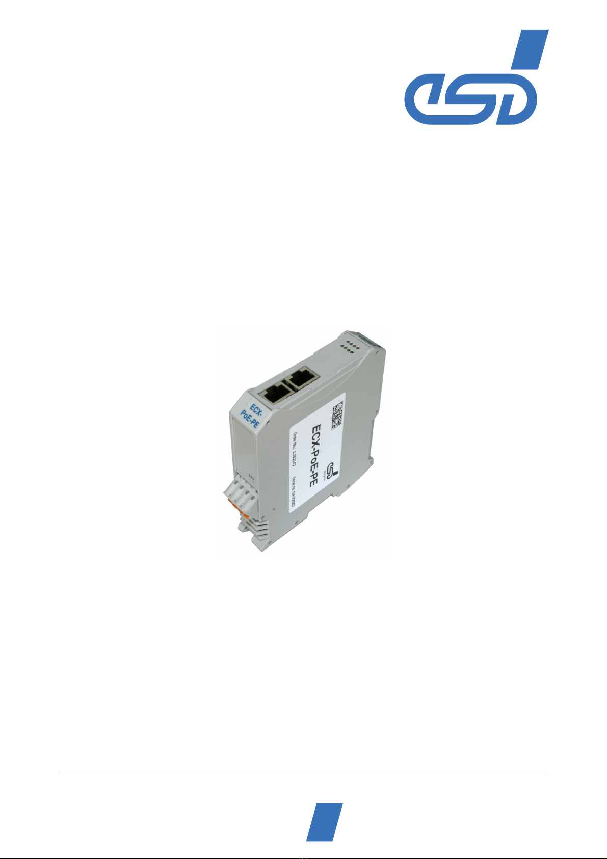
ECX-PoE-PEPage 4 of 25
Safety Instructions
!When working with ECX-PoE-PE follow the instructions below and read the manual carefully to
protect yourself and the ECX-PoE-PE from damage.
!Do not open the housing of the ECX-PoE-PE
!In order to prevent overvoltage damage due to thunder storm, unplug the ECX-PoE-PE beforehand.
!Never let liquids get inside the ECX-PoE-PE. Otherwise, electric shocks or short circuits may result.
!Protect the ECX-PoE-PE from dust, moisture and steam.
!Protect the ECX-PoE-PE from shocks and vibrations.
!The ECX-PoE-PE may become warm during normal use. Always allow adequate ventilation around
the ECX-PoE-PE and use care when handling.
!Do not operate the ECX-PoE-PE adjacent to heat sources and do not expose it to unnecessary thermal
radiation. Ensure an ambient temperature as specified in the technical data.
!Do not use damaged or defective cables to connect the ECX-PoE-PE.
Conformity
The ECX-PoE-PE is an industrial product and meets the demands of the EU regulations and EMC standards
for industrial environments printed in the conformity declaration at the end of this manual.
Warning: In a residential, commercial or light industrial environment the ECX-PoE-PE may cause radio
interferences in which case the user may be required to take adequate measures.
Qualified Personal
This documentation is directed exclusively towards qualified personal in control and automation engineering.
The installation and commissioning of the product may only be carried out by qualified personal, which is
authorized to put devices, systems and electric circuits into operation according to the applicable national
standards of safety engineering.
Intended Use
The intended use of the ECX-PoE-PE is the operation as a power extractor for InRailBus, applicable with ECX
and CBX units. The esd guarantee does not cover damages which result from improper use, usage not in
accordance with regulations or disregard of safety instructions and warnings.
!The ECX-PoE-PE is intended for indoor installation only.
!The operation of the ECX-PoE-PE in hazardous areas, or areas exposed to potentially explosive
materials is not permitted.
!The operation of the ECX-PoE-PE for medical purposes is prohibited.
Service Note
The ECX-PoE-PE does not contain any parts that require maintenance by the user. The ECX-PoE-PE does not
require any manual configuration of the hardware. Unauthorized intervention in the device voids warranty
claims.
Remove all cables before cleaning. Clean the device with a slightly moist, lint-free cloth. Cleaning agents or
solvents are not suitable.
Disposal
Devices which have become defective in the long run have to be disposed in an appropriate way or have to be
returned to the manufacturer for proper disposal. Please, make a contribution to environmental protection.

ECX-PoE-PE
Manual • Doc.-No.: E.3020.21 / Rev. 1.0
Page 5 of 25
Contents
1. Overview ....................................................................7
1.1DescriptionoftheModule ............................................7
2. Technical Data ...............................................................9
2.1General technicalData...............................................9
2.2Microcontroller ....................................................10
3. Hardware Installation ........................................................11
3.1ConnectingDiagram ................................................11
3.2LEDDisplay ......................................................12
3.2.1 Operation of the System LED S . . . . . . . . . . . . . . . . . . . . . . . . . . . . 12
3.2.2 Operation of the PoE LEDs P, + . . . . . . . . . . . . . . . . . . . . . . . . . . . 13
3.2.3 Operation of the Temperature LED T . . . . . . . . . . . . . . . . . . . . . . . . 13
3.2.4 Operation of the Current LEDs 1, 2, 3 and W . . . . . . . . . . . . . . . . . . 14
3.3 Power Derating Depending on the Mounting Position . . . . . . . . . . . . . . . . . . . . . . 15
3.4 Installation of the Module Using InRailBus Connector . . . . . . . . . . . . . . . . . . . . . 16
3.4.1 Connection of the Power Supply Voltage . . . . . . . . . . . . . . . . . . . . . 16
3.4.2 Module Installation Using a Mounting Rail Bus Connector . . . . . 17
3.4.3 Connecting Power Supply to InRailBus . . . . . . . . . . . . . . . . . . . . . . 19
3.5 Remove the ECX Module from the InRailBus . . . . . . . . . . . . . . . . . . . . . . . . . . . . 19
4. Connector Assignment ........................................................20
4.1 Power Supply Voltage 24 V (X201) . . . . . . . . . . . . . . . . . . . . . . . . . . . . . . . . . . . . 20
4.2ETH(X400) ......................................................21
4.3 Power Supply Voltage via InRailBus Connector (X200) . . . . . . . . . . . . . . . . . . . . 21
4.4Ethernet(X110,X120) ..............................................22
5. Quick Start Guide ...........................................................23
6. Declaration of Conformity ....................................................24
7. Order Information ...........................................................25

Manual • Doc.-No.: E.3020.21 / Rev. 1.0
ECX-PoE-PEPage 6 of 25
This page is intentionally left blank.

Overview
ECX-PoE-PE
Manual • Doc.-No.: E.3020.21 / Rev. 1.0
Page 7 of 25
+24 V=
+48 V=
LEDs
Photo
Coupler
InRailBus
Connector
MEMAX
Po er Connector
MSTBO 2,5/4-
G1L-KMGY
DC/DC
Converter
Module
OVP
Gigabit Ethernet
DATA&PoE
RJ45
RJ45
DATA
Microcontroller
(PIC16)
SW-PoE
-
+
I
OUT
24V
ϑ
1. Overview
1.1 Description of the Module
Fig. 1: Block circuit diagram of the ECX-PoE-PE module
The ECX-PoE-PE is a power extractor that provides 24 V power supply voltage for the InRailBus.
It can be used for ECX and CBX units.
The power supply voltage is fed via the Ethernet lines (PoE).
The module is designed for hat-rail mounting in a control enclosure. The connectors and status LEDs
are mounted in the front panel.
The ECX-PoE-PE supports IEEE 802.03at (PoE+, layer 1 only), and is compatible with IEEE 802.03af
(Class 4).
Ethernet data (10/100/1000BASE-T) is electrically passed through.
The ECX-PoE-PE comes with LEDs which indicate the state of operation and the states of the
temperature- and the output current control.

Übersicht
Manual • Doc.-No.: E.3020.21 / Rev. 1.0
ECX-PoE-PEPage 8 of 25
The following figure shows an example for the usage of the ECX-PoE-PE module.
Fig. 2: Exemplary installation of the ECX-PoE-PE
The ECX-PoE-PE receives the Ethernet data and the power supply for the InRailBus from the Power
Source Equipment (PSE). The 24 V power supply voltage is fed into the InRailBus and the Ethernet
data is electrically passed through to the Powered Devices (PD), e.g. to ECX-DIO8.

Technical Data
ECX-PoE-PE
Manual • Doc.-No.: E.3020.21 / Rev. 1.0
Page 9 of 25
2. Technical Data
2.1 General technical Data
Input voltage 36 - 57 V/DC
Output voltage 24 V ± 5%
Power output maximum 25 W
(Derating from approximately 33
/
C or 41
/
C, depending on the
mounting position, see page 15)
Connectors
ETH/PoE (8-pin RJ45 jack, X110) - Ethernet Data, Power over
Ethernet (PoE)
ETH (8-pin RJ45 jack, X120) - Ethernet Data
24V (4-pin COMBICON connector with spring-cage connection,
X201) - 24V-power supply voltage
InRailBus (5-pin ME-MAX-TBUS-connector, Phoenix Contact, X200)
- power supply voltage for InRailBus
Temperature range -20 ... + 60
/
C ambient temperature
Humidity max. 90%, non-condensing
Protection class IP20
Pollution degree maximum permissible according to DIN EN 61131-2:
Pollution Degree 2
Housing Plastic housing for carrier rail mounting NS35/7,5 DIN EN 60715
Dimensions width: 22.5 mm, length: 99 mm, constructional height: 114.5 mm
(dimensions without mating connectors)
Weight approx. 135 g
Table 1: General technical data

Technical Data
Manual • Doc.-No.: E.3020.21 / Rev. 1.0
ECX-PoE-PEPage 10 of 25
2.2 Microcontroller
Microcontroller PIC16, 8 MHz
Table 2: Microcontroller
2.3 EtherNet Data & Data/PoE
Ethernet data (10/100/1000BASE-T), electrically passed through
PoE supply according to IEEE 802.03at (PoE+, only layer 1 is supported),
and compatible with IEEE 802.03 af (Class 4)
Table 3: Data of analog inputs

Hardware Installation
ECX-PoE-PE
Manual • Doc.-No.: E.3020.21 / Rev. 1.0
Page 11 of 25
3. Hardware Installation
3.1 Connecting Diagram
Fig. 3: Connections of the ECX-PoE-PE module
The connector pin assignment can be found on page 20 and following.
Note: For the connection of the Ethernet interfaces use cables of type:
unshielded twisted-pair, minimum Cat 5 U/UTP cable

Hardware-Installation
Manual • Doc.-No.: E.3020.21 / Rev. 1.0
ECX-PoE-PEPage 12 of 25
S P + T
ETH
ETH/PoE
1 2 3 W
3.2 LED Display
Fig. 4: Position of the LEDs in the front panel
The ECX-PoE-PEmodule is equippedwith 8 LEDs. Theindicator states are described inthe following
chapters.
The system LED S indicates the state of the system power. All other LEDs only indicate, if the power
supply voltage is fed via the Ethernet lines (PoE).
3.2.1 Operation of the System LED S
LED indication Display function
LED-Name
in
Schmatics
Diagram
Label Name Colour Indicator
state Description
S System green off power off
LED320A
on System power on, supply via 24 V connector
or via PoE
Table 4: Indicator states of the system LED S

Hardware Installation
ECX-PoE-PE
Manual • Doc.-No.: E.3020.21 / Rev. 1.0
Page 13 of 25
3.2.2 Operation of the PoE LEDs P, +
LED indication Display function
LED-Name
in
Schmatics
Diagram
Label Name Colour Indicator
state Description
P PoE green off System power supply via 24 V connector
LED320B
on System power on, supply via PoE
+ PoE+ yellow off System power on, supply via PSE according
to 802.3af (PoE = 15 W)
LED320C
on System power on, supply via PSE according
to 802.3at (PoE+ = 30 W)
Table 5: Indicator states of the PoE and PoE+ LED
3.2.3 Operation of the Temperature LED T
The temperature LED only indicates, if the power supply voltage is fed via the Ethernet lines (PoE).
LED indication Display function
LED-Name
in
Schmatics
Diagram
Label Name Colour Indicator
state Description
T Temperature red
off Temperature OK
LED320D
blinking Temperature Warning
on Temperature Error
Table 6: Indicator states of the red temperature LED

Hardware-Installation
Manual • Doc.-No.: E.3020.21 / Rev. 1.0
ECX-PoE-PEPage 14 of 25
3.2.4 Operation of the Current LEDs 1, 2, 3 and W
LED indication
LED-Name in
Schmatics
Diagram
Label Name Colour Description
1 Current1 green In Combination, these LEDs indicate the current
load state as described in the following table.
The LEDs only indicate, if the power supply
voltage is fed via the Ethernet lines (PoE).
LED321A
2 Current2 green
LED321B
3 Current3 yellow
LED321C
W Current4 red
LED321D
Table 7: Indicators 1, 2, 3, W
Load
State LED 1 LED 2 LED 3 LED W Load (referred to I
Nom
)
0 - - - - 0% ... 5 %
1 B - - - 5 % ... 10 %
2 X - - - 10 % ... 25 %
3 X B - - 25 % ... 45 %
4 X X - - 45 % ... 70 %
5 X X B - 70 % ... 80 %
6 X X X - 80 % ... 90 %
7 X X X B 90 % ... 100 %
8 - - - X > 100 %
Table 8: Current load
Description
- ... LED off
B ... LED blinking
X ... LED on
Load referred to I
Nom
, I
Nom
depends on the standard used for the PSE
PSE according to 802.3at (PoE+ = 25 W), I
nom
= 1.042 A
PSE according to 802.3af (PoE = 12.5 W), I
Nom
= 0.520 A

Hardware Installation
ECX-PoE-PE
Manual • Doc.-No.: E.3020.21 / Rev. 1.0
Page 15 of 25
10 20 30 40 50 60
10
20
30
T
amb
[°C]
45
33
Power
[W]
14.6
24
10 20 30 40 50 60
10
20
30
T
amb
[°C]
45
41
Power
[W]
17.3
24
3.3 Power Derating Depending on the Mounting Position
ThepowerderatingoftheECX-PoE-PEdependsonthemountingpositionoftheECX-PoE-PE module
(EUT) and the neighbouring modules (P1, P2) on the mounting rail.
The following examples show the measured power derating depending on the mounting position.
Example H1: Neighbouring modules P1 and P2 on the left and on the right side, without space.
Example H2: Neighbouring modules P1 and P2 on the left and on the right side, with a space of
approximately 20mm.
In both cases no additional heat has been produced in the modules P1 and P2.
Examples for power derating depending on mounting position:
Mounting position H1 Mounting position H2
With mounting position H1 the power derates
from 24 W at 33
/
C
to 14.6 W at 60
/
C
With mounting position H2 the power derates
from 24 W at 41
/
C
to 17.3 W at 60
/
C

Hardware-Installation
Manual • Doc.-No.: E.3020.21 / Rev. 1.0
ECX-PoE-PEPage 16 of 25
!
3.4 Installation of the Module Using InRailBus Connector
3.4.1 Connection of the Power Supply Voltage
Attention!
Please note the safety instructions containing the requirements on power supply
current (see page 4).
The power supply voltage of the ECX-PoE-PE is supplied via the Ethernet lines. The ECX-PoE-PE
supplies the24 V powersupplyvoltage for the InRail Bus. Alternativelythe 24 Vpower supplyvoltage
can be supplied via the +24V power supply connector.
ECX-PoE-PE ECX-DIO8 ...
Fig. 5: ECX-Station

Hardware Installation
ECX-PoE-PE
Manual • Doc.-No.: E.3020.21 / Rev. 1.0
Page 17 of 25
Earthing of the Mounting Rail
Note: The functional earth contact (FE) has to be connected to the mounting rail. Please
note, that the impedance of the connector cable has to be kept as low as possible.
The functional earth contact is a current path of low impedance between circuits and earth, that is not
intended as protection measure, but improves the stability. It is not a protection against accidental
contact for persons.
Note: The EG conformity (see page 24) can only be warranted, if the earthing via the
mounting rail is made as described herein.
3.4.2 Module Installation Using a Mounting Rail Bus Connector
If the power supply voltage shall be fed via the InRailBus, please proceed as follows:
Figure 6: Mounting rail with bus connector
1. Position the InRailBus connector on the mounting rail and snap it onto the mounting rail using slight
pressure. Plug the bus connectors together to contact the communication and power signals (in
parallel with one). The bus connectors can be plugged together before or after mounting the ECX
module.
2. Place the ECX module with the DIN rail guideway on the top edge of the mounting rail (see
following figure).

Hardware-Installation
Manual • Doc.-No.: E.3020.21 / Rev. 1.0
ECX-PoE-PEPage 18 of 25
Figure 7 :Mounting ECX modules
3. Swivel the ECX module onto the mounting rail in pressing the module downwards according to the
arrow as shown in figure 7. The housing is mechanically guided by the DIN rail bus connector.
4. When mounting the ECX module, the metal foot catch snaps on the bottom edge of the mounting
rail. Now the module is mounted on the mounting rail and connected to the InRailBus via the bus
connector. Connect the bus connectors and the InRailBus if not already done.
Figure 8: Mounted ECX-module

Hardware Installation
ECX-PoE-PE
Manual • Doc.-No.: E.3020.21 / Rev. 1.0
Page 19 of 25
3.4.3 Connecting Power Supply to InRailBus
To connect the power supply via the InRailBus, a terminal plug (order no.: C.3000.02) is needed. The
terminal plug is not included in delivery and must be ordered separately (see order information).
Fig. 9: Mounting rail with InRailBus and terminal plug
Plug the terminal plug into the socket on the right of the mounting-rail bus connector of the InRailBus,
as described in Fig. 9. Then connect the power supply voltage via the terminal plug.
3.5 Remove the ECX Module from the InRailBus
If the ECX module is connected to the InRailBus please proceed as follows:
1. Disconnect the Ethernet lines ETH and ETH/PoE from the ECX-PoE-PE.
2. If applicable disconnect the +24 V power supply connector.
3. Release the module from the mounting rail in moving the foot catch (see Fig. 8) downwards
(e.g. with a screwdriver).
Now the module is detached from the bottom edge of the mounting rail and can be removed.

Connector Pin Assignment
Manual • Doc.-No.: E.3020.21 / Rev. 1.0
ECX-PoE-PEPage 20 of 25
4. Connector Assignment
4.1 Power Supply Voltage 24 V (X201)
Device connector: Phoenix-Contact MSTBO 2,5/4-G1L-KMGY
Line connector: Phoenix-Contact FKCT 2,5/4-ST, 5.0 mm pitch, spring-cage connection,
Phoenix-Contact order no.: 19 21 90 0 (included in the scope of delivery)
Pin Position:
Pin Assignment:
Labelling on Housing 24V
- +
Labelling on
connector - +
Pin No. 1 2 3 4
Signal P24
(+ 24 V)
M24
(GND)
M24
(GND)
P24
(+ 24 V)
Please refer also to the connecting diagram on page 11.
Signal Description:
P24... power supply voltage +24 V
M24... reference potential
Table of contents
Other ESD Network Hardware manuals
Popular Network Hardware manuals by other brands

United Technologies
United Technologies Interlogix TruVision NVR 22 S quick start guide

ZyXEL Communications
ZyXEL Communications IES-6000 - ANNEXE 749 Specifications

ATTO Technology
ATTO Technology FibreBridge 2370E Installation and operation manual

Juniper
Juniper CTP150 manual

DEWESOFT
DEWESOFT IOLITE V22-2 Technical reference manual

Cerio
Cerio CS-2000 Series user manual

Control Techniques
Control Techniques FM-3 Reference manual

Cabletron Systems
Cabletron Systems WPIM-SY Management guide

INSIGHT
INSIGHT DLP DIRECTOR 1100 Hardware installation guide

CES
CES VAD-1 installation manual

Extreme Networks
Extreme Networks ExtremeWireless AP510e installation guide

Crestron
Crestron NAT reference guide