esera automation 11134 User manual
Art. No. 11134
All rights reserved. Reproduction as well as electronic duplication of this user guide, complete or in part, requires the written consent of
ESERA GmbH. Errors and technical modification subject to change. ESERA GmbH, ESERA-Automation 2020
www.esera.de 11134 V2.0 R1.0 Manual Page 1 of 6
User Guide
Multisensor
Temperature, Humidity and Brightness
for 1-Wire Bus System
High-precision Temperature- and
precise Humidity Sensor
Connection via pressure connection terminals
and RJ45 plug connection (e.g. CAT5 network
cable)
Simple power supply (5V)
Integrated voltage monitoring
Mounting on flush-mounted sockets possible
White and discreet surface-mounted housing
with integrated ventilation slots
Application:
Heating control (individual room control)
Ventilation system control
.
1 Introduction
Before you start installing the living area sensor in order to put the device into operation, please read these
operating instructions carefully to the end, especially the section of the safety instructions.
2 Product description
With the Multisensor a simple monitoring and recording of the indoor climate is possible.
For heating systems (individual room control) and ventilation systems it is an important sensor to achieve a good
and stable control of temperature/ humidity.
The Multisensor is also optimal to warn of possible mould growth.
A calibration of the internal sensors is not necessary. The unit can be put into operation immediately without
waiting time. The Multisensor contains a 1-Wire module of type DS2438, to detect temperature, humidity,
brightness and operating voltage. The integrated humidity sensor has a high accuracy in the range of 10 - 85%
relative humidity.
A brightness sensor is used to measure twilight and brightness values within living spaces. The sensor can be
used, for example, to control roller shutters or venetian blinds on the basis of brightness. Constant lighting control
of living and working areas is also possible.
A special photodiode with a human-like detection light spectrum is used.
The 1-Wire Multisensor is designed to detect relative humidity, temperature, brightness and its own operating
voltage. The 1-Wire Multisensor has an individual 1-Wire serial number.
The sensor is intended for use in living areas.

All rights reserved. Reproduction as well as electronic duplication of this user guide, complete or in part, requires the written consent of
ESERA GmbH. Errors and technical modification subject to change. ESERA GmbH, ESERA-Automation 2020
www.esera.de 11134 V2.0 R1.0 Manual Page 2 of 6
For rooms with permanently high air humidity values, such as saunas, we recommend the
1-Wire outdoor Temperature-Humidity Sensor (Art.No: 11135).
The living area Sensor is integrated into a 1-Wire Network via screwless pressure clamps or RJ45 plug
connection (CAT cable).
The living area Sensor is designed for cable entry from the rear or side. The housing cut-outs must be adapted to
the cable entry.
3 Technical Data
1-Wire Interface: DS2438, Multisensor for temperature, humidity, brightness and operating voltage
Measuring range
Temperature: -30°C to +60°C (sensor element: -55°C to +125°C)
Accuracy Temperature: +/- 0.5° in the range from -10°C to + 85°C
Resolution: 9 bit, 0.03125°C/ bit depending on the selected resolution
Air humidity sensor: Capacitive sensor of the manufacturer Honeywell
Measuring range humidity: 0-100% rel. humidity
Humidity accuracy: +/-3.5 % (10-85% rH), +/-7% (<10% and >85% rH)
Brightness sensor: Sensor, adapted to the sensitivity of the human eye
Measuring range: 2 - 7000 Lux
Accuracy Lux: +/-25% in the range up to approx. 200 Lux, +/-15% in the range up to 7000 Lux
Operating voltage: 5 V= (+/-10%)
Power consumption: approx. 2 mA
Connection: push-in terminal and RJ45 modular socket
4 Ambient conditions
Protection system: IP20
Protection class: III
Temperature, Operation: -25°C to 80°C
Air humitidy: 10 - 90% (non condensing)
Dimensions (outside): 71 x 71 x 32mm (L x W x H)
5 Conformity
EN 50090-2-2
EN 61000-4-2, ESD
EN 61000-4-3, HF
EN 61000-4-4, Burst
EN 61000-4-5, Surge
EN 61000-6-1, Interference immunity
EN 61000-6-3, Interference radiation
RoHS
6 Software / Control
The living area sensor is read out via 1-Wire commands for DS18B20 and DS2438 devices and is supported by
many systems, such as ESERA 1-Wire Controller, ESERA 1-Wire Gateway, Loxone PLC, WAGO PLC (via
OWOS), OWFS, FHEM (Linux), IP-Symcon or microcontroller applications.
7 Control via 1-Wire Controller / 1-Wire Gateway
The control and data output of the 1-Wire outdoor sensor via the 1-Wire Controller / 1-Wire Gateway is very
simplified. The current sensor data is output continuously. No query of the data is necessary and available.
If you have assigned the article number (11134) of the OWD number of this sensor via ESERA Config Tool 3,
you will henceforth receive data sets adapted to the sensor. Thus, no further formulas are necessary.
7.1 Data output 1-Wire Controller / 1-Wire Gateway
The following data formats are output for the ESERA-Automation modules. If you divide the value by 100, you get
the data with two decimal places.
Data output
1_OWD1_1|2008 => Controller No._Module No._Data set|Temperature (°C) example: 20,08 °C
1_OWD1_2|511 => Controller No._Module No._Data set|Voltage VCC (V)
1_OWD1_3|850 => Controller No._Module No._Data set|Air humitidy (rF) example: 85,0%
1_OWD1_4|1200 => Controller No._Module No._Data set|Dew point (°C) example: 12,00 °C
1_OWD1_5|80000 => Controller No._Module No._Data set|Brightness (Lux) example: 800,00 Lux
Further information on the possibilities and commands can be found in the current programming manual of the 1-
Wire Controller /1-Wire Gateway, which can be found within Config Tool 3.

Art. No. 11134
All rights reserved. Reproduction as well as electronic duplication of this user guide, complete or in part, requires the written consent of
ESERA GmbH. Errors and technical modification subject to change. ESERA GmbH, ESERA-Automation 2020
www.esera.de 11134 V2.0 R1.0 Manual Page 3 of 6
8 Integration in IP-Symcon
On our website, we provide ESERA IP-Symcon software modules for easy integration of the sensor into IP-
Symcon via 1-Wire Controller / 1-Wire Gateway. This means that no scripts are required any more.
Details can be found on the ESERA website under "Compatible controllers / Centralized IP-Symcon integration".
https://www.esera.de/kompatible-steuerungen-zentralen/ip-symcon-integration/
A script for the conventional connection via 1-Wire Bus Coupler can be found in the article download area. Details
can be found in the example script.
9 Integration in Loxone
Via the shop we provide a sample project for reading of temperature, humidity, dew point, brightness and
operating voltage via 1-Wire Controller / 1-Wire Gateway.
Details see here:
https://www.esera.de/service-support/kompatible-steuerungen-zentralen/loxone-integration/
10 Integration in FHEM
For the integration into the open source automation software FHEM we provide a software module for easy
integration of the sensor into FHEM via 1-Wire Controller / 1-Wire Gateway. Thus no more evaluation scripts are
necessary.
Details can be found on the ESERA website at „Kompatible Steuerungen / Zentralen/FHEM-Integration“
https://www.esera.de/service-support/kompatible-steuerungen-zentralen/fhem-integration/
11 Manual calculation of sensor values
The following formula can be used to evaluate the humidity sensor.
VDD = operating voltage (5V), VAD = humidity sensor, analog value of DS2438, Xsense = light sensor, analog
value of DS2438.
Humidity calculation
Offset = 0.847847 (Zero Offset V), slope = 29.404604 (Slope: mV/ %RH)
Srh = (VAD_new - offset) / (slope / 1000)
rFH = (Srh + 2)/ ((1.0305 + (0.000044 * temperature) - (0.0000011 * temperature x 10²)))
For Loxone control:
I1 = VAD-value, I3 = Temperature
((((5/I2*I1)-0,847847)/(29,404604/1000))+2)/((1,0305+(0,000044*I3)-(0,0000011*I3^2)))
Brightness calculation
Xsense in Volt, Factor = 25600
Correction for operating voltage fluctuations: Xsense = (5 / VDD) * Xsense
Brightness (LUX) = (0,223V - Xsense) * Factor
Note on brightness measurement:
It should be noted that the placement of light sources in relation to the angle of incidence of the Multisensor may
cause considerable deviations in the brightness readings of hand-held brightness meters.
Brightness control:
In the case of illumination with fluorescent or LED lamps, the value may additionally fluctuate. A living room
brightness control is usually impaired by strongly changing lighting conditions, e.g. shadows cast by people in the
room and the resulting fluctuations in sensor light values, and a well-functioning control function is often difficult to
implement. This is largely due to the unfavourable positioning in the light switch area for measuring the brightness
of the Multisensor.
All rights reserved. Reproduction as well as electronic duplication of this user guide, complete or in part, requires the written consent of
ESERA GmbH. Errors and technical modification subject to change. ESERA GmbH, ESERA-Automation 2020
www.esera.de 11134 V2.0 R1.0 Manual Page 4 of 6
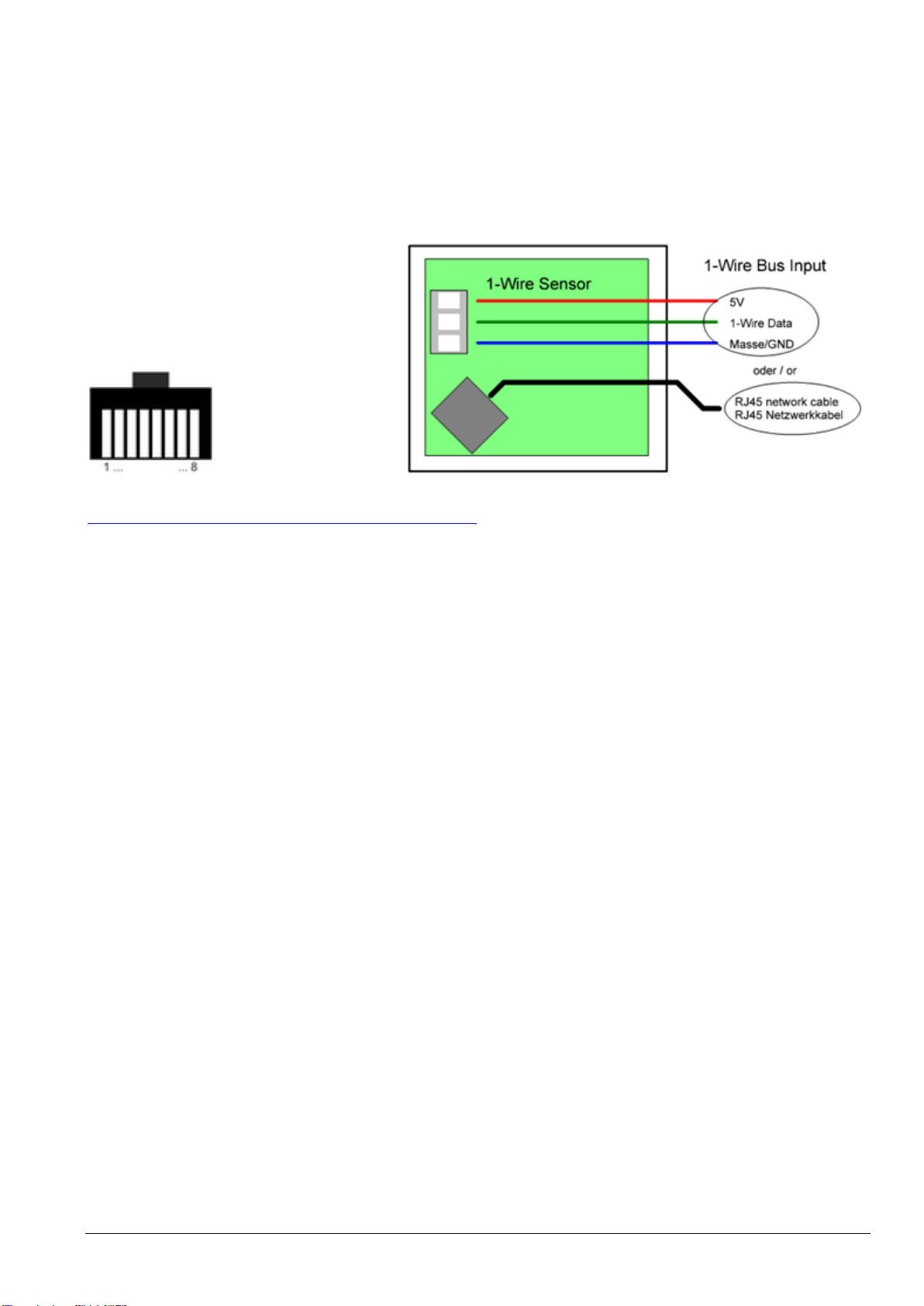
12 Pin assignment
The temperature and humidity sensor is connected via push-in terminals (screwless terminal) or RJ45 modular
socket. The connection terminal is intended for solid cables with a cross section of 0.2 to 2.5 sq. mm or fine
stranded cables with a cross section of 0.2 to 1.5 sq. mm.
The terminal assignment of the screw terminals is printed on the printed circuit board. The correct polarity must
be observed when connecting.
The Multisensor must be supplied with three cables (ground, 1-Wire Data and 5V). The parasitic mode is not
supported.
Pin assignment RJ45 socket
1 = GND 5= GND
2 = +5V 6 = not connected
3 = GND 7 = not connected
4 = 1-Wire 8 = GND
1-Wire primary and 1-Wire secondary
not connected
Note: Basics and tips for the 1-Wire bus system can be found on the ESERA website at
https://www.esera.de/service-support/1-wire-grundlagen/
13 1-Wire Network Cabling
For short connection lengths, no special requirements are placed on the cable used. With unshielded cable,
e.g. telephone cable J-Y(St)Y telephone line 4x2x0.8, 1-wire networks can be set up in star or tree wiring of
approx. 30 - 80m. We recommend the use of CAT 5-7 network cable for installation. For cable assignment
you will find a recommendation in the article download.
Shielded cable, e.g. CAT5 or CAT6 cable should be used in the Smart Home, in commercial buildings and in
industrial environments. This ensures a very good system stability of the entire system. Another advantage
of cabling with CAT cable is that a linear bus topology can be achieved despite star-shaped cable routing in
buildings. This is only possible due to the 8-wire cable structure of the CAT cable.
When using CAT7 cable, the maximum possible cable length of the entire 1-wire network is reduced due to
the stronger shielding and the resulting higher cable capacity.
With star or tree cabling with CAT cable, a total length of approx. 50-100m can be calculated, which
corresponds to 1-2 floors in a residential building.
In general, unnecessary cable connections, branches or cable extensions should be avoided. Each joint or
clamp connection reduces the maximum available network size.
The special feature of wiring multi-sensors with 1-Wire BUS technology is that all sensors are operated via a
three-wire cable. Both power supply and data communication take place via the bus line.
14 Operating conditions
The module may only be operated at the specified voltages and ambient conditions. The device can be
operated in any position. The device is intended for use in dry and dust-free rooms.
If condensation is formed, wait at least 2 hours for the unit to acclimatize.
Do not operate the module in an environment in which flammable gases, vapors or dusts are present or may
be present.
15 Assembly
The Multisensor should be mounted upright with the ventilation openings at the top and bottom. It is intended for
temperature and humidity measurement of air and gases in indoor areas, such as living rooms, offices,
workshops or public facilities. The measured values specified under technical data are limit data for the entire 1-
Wire Multisensor and must not be exceeded or fallen short of, as the Multisensor may otherwise be damaged.

Art. No. 11134
All rights reserved. Reproduction as well as electronic duplication of this user guide, complete or in part, requires the written consent of
ESERA GmbH. Errors and technical modification subject to change. ESERA GmbH, ESERA-Automation 2020
www.esera.de 11134 V2.0 R1.0 Manual Page 5 of 6
16 Disposal instructions
Do not dispose of the device in household waste! Electronic instruments are to be disposed
of according to the Directive on Waste Electrical and Electronic Equipment on local
Collection points for electronic waste must be disposed of!
17 Safety instructions
When using products that come into contact with electrical voltage, the valid VDE regulations must be
observed, especially VDE 0100, VDE 0550/0551, VDE 0700, VDE 0711 and VDE 0860
All final or wiring work must be carried out with the power turned off.
Before opening the device, always unplug or make sure that the unit is disconnected from the mains.
Components, modules or devices may only be put into service if they are mounted in a contact proof housing. During
installation they must not have power applied.
Tools may only be used on devices, components or assemblies when it is certain that the devices are disconnected
from the power supply and electrical charges stored in the components inside the device have been discharged.
Live cables or wires to which the device or an assembly is connected, must always be tested for insulation faults or
breaks.
If an error is detected in the supply line, the device must be immediately taken out of operation until the faulty cable
has been replaced.
When using components or modules it is absolutely necessary to comply with the requirements set out in the
accompanying description specifications for electrical quantities.
If the available description is not clear to the non-commercial end-user what the applicable electrical characteristics for
a part or assembly are, how to connect an external circuit, which external components or additional devices can be
connected or which values these external components may have, a qualified electrician must be consulted.
It must be examined generally before the commissioning of a device, whether this device or module is basically
suitable for the application in which it is to be used.
In case of doubt, consultation with experts or the manufacturer of the components used is absolutely necessary.
For operational and connection errors outside of our control, we assume no liability of any kind for any resulting
damage.
Kits should be returned without their housing when not functional with an exact error description and the
accompanying instructions. Without an error description it is not possible to repair. For time-consuming assembly or
disassembly of cases charges will be invoiced.
During installation and handling of components which later have mains potential on their parts, the relevant VDE
regulations must be observed.
Devices that are to be operated at a voltage greater than 35 VDC / 12mA, may only be connected by a qualified
electrician and put into operation.
Commissioning may only be realized if the circuit is built into a contact proof housing.
If measurements with an open housing are unavoidable, for safety reasons an isolating transformer must be installed
upstream or a suitable power supply can be used.
After installing the required tests according to DGUV / regulation 3 (German statutory accident insurance,
https://en.wikipedia.org/wiki/German_Statutory_Accident_Insurance) must be carried out.
18 Warranty
ESERA GmbH guarantees that the goods sold at the time of transfer of risk to be free from material and workmanship
defects and have the contractually assured characteristics. The statutory warranty period of two years begins from date of
invoice. The warranty does not extend to the normal operational wear and normal wear and tear. Customer claims for
damages, for example, for non-performance, fault in contracting, breach of secondary contractual obligations,
consequential damages, damages resulting from unauthorized usage and other legal grounds are excluded. Excepting to
this, ESERA GmbH accepts liability for the absence of a guaranteed quality resulting from intent or gross negligence.
Claims made under the Product Liability Act are not affected.
If defects occur for which the ESERA GmbH is responsible, and in the case of replacement goods, the replacement is
faulty, the buyer has the right to have the original purchase price refunded or a reduction of the purchase price.
ESERA GmbH accepts liability neither for the constant and uninterrupted availability of the ESERA GmbH or for technical
or electronic errors in the online offer.
We develop our products further and we reserve the right to make changes and improvements to any of the products
described in this documentation without prior notice. If you need documentation or information about older product
This manual suits for next models
1
Table of contents
Other esera automation Accessories manuals

esera automation
esera automation 11112 User manual

esera automation
esera automation Multisensor Pro I User manual

esera automation
esera automation Multisensor 11132 Gen2 User manual

esera automation
esera automation Windsensor Pro 200 User manual

esera automation
esera automation 11150 User manual

esera automation
esera automation 20002 User manual

esera automation
esera automation MS 100 User manual

esera automation
esera automation Multisensor Pro 11150 User manual


