esera automation 11112 User manual

Art. No. 11112
All rights reserved. Reproduction as well as electronic duplication of this guide, complete or in part, requires the written consent of ESERA-
Automation or E-Service GmbH. Errors and technical modification subject to change. ESERA-Automation, E-Service GmbH 2019
www.esera.de 11112 V1.0 R1.0 Manual Page 1 of 5
User Guide
Solar Multisensor V4
for 1-Wire bus system
Single beam sensor based on a photovoltaic cell
Separate brightness sensor
Detection of ambient brightness,
day / night detection
Integrated temperature sensor for temperature
measurement for "perceived temperature”or
outside temperature
Waterproof sensor housing (IP54)
Connection via Push In terminal for cable
up to 1,5qmm cross-section
Easy to assemble
1 Introduction
Before you start mounting the 1-Wire Solar Multisensor and putting the device into operation, please read these
mounting and operating instructions carefully until the end, especially the section on safety instructions.
2 Product description
The 1-Wire Solar Multisensor is a combination sensor for solar-radiation, brightness and perceived temperature
that combines the advantages of semiconductor and photovoltaic sensors in one device.
The brightness sensor measures brightness values in the range of 10 - approx. 7000 lux, the PV sensor covers the
range up to approx. 1200W/m² and the temperature sensor outputs the felt temperature in the sun.
Since the solar sensor is a power sensor, the output is in watts per square meter (W/m²). The solar and brightness
sensors with their supplementary properties cover the entire range of applications for recording solar-radiation and
day/night detection and are therefore ideally suited for central light-, shutter- and shade control.
The 1-Wire Solar Multisensor is designed for permanent outdoor operation. The entire sensor is designed for a
temperature range of -40 to +85°C.
To ensure maximum reliability, the 1-Wire Solar Multisensor has an integrated monitoring of the supply voltage.
The sturdy plastic housing is designed for IP54 operating conditions. The cable entry is made by screw strangling
nipples. For wall mounting, a special mounting bracket is available for purchase as an accessory at our shop.
2.1 Photovoltaic sensor (solar sensor)
The photovoltaic sensor is designed to measure the solar-radiation in W/m². This makes the solar Multisensor very
suitable for controlling shading- or awning systems. The solar sensor covers an enormously large dynamic range
up to approx. 1200 W/m², which corresponds to approx. 1,000 up to 70,000 lux.
The sensor can be used well for estimating the expected performance of PV systems and finding a location.
Existing PV systems can be monitored by comparison measurements. Due to its design, the output voltage of the
sensor does not run with a linear characteristic curve and is subject to a certain temperature influence.
The measured solar-radiation power of the solar cell is output in watts per square meter (W/m²) by formula,
(evaluation script) and a variable for controlling a shading system is output.
The solar sensor is typically mounted on a mounting bracket (Art. No. 20003) at an inclination of approx. 45° with
orientation to the south. This allows a comparative measurement for PV systems. Rain and snow will also slide
faster from the top of the sensor.

All rights reserved. Reproduction as well as electronic duplication of this guide, complete or in part, requires the written consent of ESERA-
Automation or E-Service GmbH. Errors and technical modification subject to change. ESERA-Automation, E-Service GmbH 2019
www.esera.de 11112 V1.0 R1.0 Manual Page 2 of 5
2.2 Brightness sensor
The brightness sensor is used for the measurement of low light values and for sunrise and sunset detection. For
example, blinds can be opened or closed in the morning and evening.
A special photodiode, with a human-like detection light spectrum, converts the ambient brightness to an analog
voltage value.
The evaluation script converts the output voltage value to the current brightness value in lux and outputs a variable
for day / night control, e.g. for roller shutter control.
2.3 Temperature sensor
The solar Multisensor contains a temperature sensor that measures the temperature felt in the sun. Depending on
the weather conditions, the temperature values can deviate greatly from those measured near the ground. By
mounting the temperature sensor inside the housing, short-term falsifications of measured values due to draughts
or gusts of wind are greatly reduced.
With the temperature sensor, comparative temperature values for mounted PV modules can be easily recorded and
used to calculate the possible power reduction and plausibility check.
Depending on the installation location, the sensor can also be used as an outdoor temperature sensor. For the
exact recording of the normal outdoor temperature we recommend our 1-Wire temperature sensor waterproof, Art.
No. 11111 or the 1-Wire Multisensor Temperature, Humidity and Brightness, Art. No. 11135.
3 Technical data
1-Wire chip/device 1 x DS2438 (Multisensor)
Solar sensor Measuring range up to approx. 1200 W/m2 (converted approx. 1,000 - 70,000 lux)
PV measuring cell is a high-quality monocrystalline glass PV cell
Detection range: +/-50° (for half sensitivity)
Functions DS2438: XSens, 0mV = darkness, resolution 10mV, 10 Bit
Brightness sensor Measuring range 10 - approx. 7000 Lux,
Peak sensitivity 570 nm, light sensitivity similar to the human eye
Detection range: +/-50° for half sensitivity
Functions DS2438: VAD, brightness value (5V = darkness), 0 - 5V, resolution 10mV, 10 Bit
Temperature sensor Measuring range -50°C to +125°C, resolution 0.03125°C, 13 Bit
Interface: 1-Wire Bus (5V, Data and Ground)
Operating voltage: 5 V= (+/-10%), resolution 10mV, 10 Bit
Current consumption: max. 2mA @ 5V (light sensor full scale)
Connection: Screwless pressure terminals for cables up to 1.5qmm cross-section
4 Ambient conditions
Protection type: IP54
Protection class: III
Temperature, Operation:-40°C to +85°C
Humidity: 10 - 92% (non-condensing)
Dimensions: 82 x 80 x 57mm (L x W x H) without cable gland
Housing color: Light grey
Housing material: ABS plastic (acrylonitrile-butadiene-styrene)
5 Conformity
EN 50090-2-2,
EN 61000-4-2 ESD,
EN 61000-4-3 HF,
EN 61000-4-4 Burst,
EN 61000-4-5 Surge,
EN 61000-6-1 Fault-free operation,
EN 61000-6-3 Stray radiation,
RoHS
6 Software
The solar multisensor is read by 1-Wire commands for DS2438 device and supported by many software programs
and devices, such as Loxone SPS, WAGO SPS (via OWOS), OWFS, FHEM (Linux), IP-Symcon or microcontroller
applications.
Assignment of DS2438 inputs: VDD = operating voltage (Volt), VAD = brightness (Volt), XSENS = irradiation (Volt).
Evaluation brightness sensor:
Brightness (Lux) = (VDD-VAD) * 700, example: (5V-1.25 V) * 700 = 2625 lux
Note: it should be noted that the sensor has a negative evaluation, which means approx. 5V equals darkness and
approx. 0V equals full lighting.

Art. No. 11112
All rights reserved. Reproduction as well as electronic duplication of this guide, complete or in part, requires the written consent of ESERA-
Automation or E-Service GmbH. Errors and technical modification subject to change. ESERA-Automation, E-Service GmbH 2019
www.esera.de 11112 V1.0 R1.0 Manual Page 3 of 5
Evaluation solar sensor:
Basis for the reference measurements are 800W/m².
Solar-radiation (W/m²) = (XSENS * 5040), example 0.047 V * 5040 = 236.88 W/m²
7 Control via 1-Wire Controller / 1-Wire Gateway
The 1-Wire interface of the 1-Wire PV solar-, brightness- and temperature sensor is controlled by standard
commands for the DS2438 module. The 1-Wire Controller / 1-Wire Gateway has already stored a suitable formula
for converting the raw data of the 1-Wire module. All you have to do is assign the article number 11112 to the
corresponding OWD number using the Config Tool.
7.1 Data output 1-Wire Controller / 1-Wire Gateway
The following data is output for the ESERA-Automation 1-Wire PV solar, brightness and temperature sensor 11112.
If you divide the value by 100, you receive the data with two decimal places.
Data output:
1_EVT|10:29:35
1_OWD1_1|2401 => Controller No._device No._data record | Temperature (°C) example: 20,08 °C
1_OWD1_2|501 => Controller No._device No._data record | Operating voltage (V) example 5,01 V
1_OWD1_3|741000 => Controller No._device No._data record | Brightness (Lux) example: 7410,00 Lux
1_OWD1_4|7676 => Controller No._device No._data record | Solar radiation (W/m2) example: 76,76 W/m2
Further information on the possibilities and commands can be found in the current documentation 1-Wire Controller
/1-Wire Gateway.
8 Integration in IP-Symcon / ESERA-Station
At our website we provide ESERA IP-Symcon software modules for reading the 1-Wire Multisensor into IP-
Symcon via 1-Wire Controller / 1-Wire Gateway. No scripts are necessary. Details can be found on the
ESERA website under "Compatible control systems/central control systems/IP-Symcon integration".
https://www.esera.de/kompatible-steuerungen-zentralen/ip-symcon-integration/
For the conventional connection via 1-Wire Bus Coupler, the sensor values must be calculated according to
the specified formulas.
9 Integration in Loxone
Via the shop we provide an example project for reading the 1-Wire Multisensor via 1-Wire Controller 1/1-Wire
Gateway. Details see here: https://www.esera.de/kompatible-steuerungen-zentralen/loxone-integration/demo-1-
wire-controller-1-loxone-integration/
10 Integration in FHEM
For the integration into the open source automation software FHEM we provide a software module for reading the
1-Wire Multisensor via 1-Wire Controller / 1-Wire Gateway. This eliminates the need for evaluation scripts.
Details can be found on the ESERA website under "Compatible Controls - Central Units / FHEM
Integration".https://www.esera.de/kompatible-steuerungen-zentralen/fhem-integration/
11 Assembly and application instructions
The sensor should be attached to a vertical or inclined surface, e.g. with the mounting bracket (Art. No. 20003) at
an angle of 45°. The inlet for the supply cable should point downwards. This is to avoid back pressure caused by
rain or snow on the cable gland.
As connection cable we recommend our PUR sensor cable (Art. No. 11114).
The maximum cable length is 100 m. The device is intended for installation as a stationary device.
If the 1-Wire PV solar, brightness and temperature sensor is operated on a 1-Wire network, we recommend
termination of the cable end with the 1-Wire Term 1 (Art. No. 11355).

All rights reserved. Reproduction as well as electronic duplication of this guide, complete or in part, requires the written consent of ESERA-
Automation or E-Service GmbH. Errors and technical modification subject to change. ESERA-Automation, E-Service GmbH 2019
www.esera.de 11112 V1.0 R1.0 Manual Page 4 of 5
12 Connection plan
The 1-Wire solar sensor is connected via Push In terminals. The connection terminal is intended for solid wires
or finely stranded cables of 0.2 to 1.5qmm cross-
section.
The pin assignment is printed on the printed
circuit board.
The correct polarity of the connection must be
observed.
The Multisensor is equipped with three cables
(ground, 1-Wire Data and 5V).
Parasitic mode is not supported.
Note: Basics and tips for the 1-Wire bus system
can be found on the ESERA website at
https://www.esera.de/1-wire-grundlagen/
13 Assembly
If the sensor is used to control shades or roller shutters, the sensor should be oriented to the south. If room lighting
is to be controlled, orientation to the north is preferable. Ensure that the sensor is not shaded by trees or chimneys.
14 Operating conditions
The module may only be operated at the specified voltages and ambient conditions. The device can be
operated in any position. The sensor is designed for continuous operation outdoors or in rooms with high
humidity.
If condensation forms inside the sensor, an acclimatization time of at least 2 hours must be waited for.
Do not operate the module in an environment in which flammable gases, vapors or dusts are present or may be
present.
15 Disposal note
Do not dispose of the device within the household waste!
According to the directive concerning old electrical and electronic appliances,
electronic devices must be disposed of via the collecting points for old electronic
appliances!
16 Safety instructions
When using products that come into contact with electrical voltage, the valid VDE regulations must be observed, especially VDE
0100, VDE 0550/0551, VDE 0700, VDE 0711 and VDE 0860
All final or wiring work must be carried out with the power turned off.
Before opening the device, always unplug or make sure that the unit is disconnected from the mains.
Components, modules or devices may only be put into service if they are mounted in a contact proof housing. During
installation they must not have power applied.
Tools may only be used on devices, components or assemblies when it is certain that the devices are disconnected
from the power supply and electrical charges stored in the components inside the device have been discharged.
Live cables or wires to which the device or an assembly is connected, must always be tested for insulation faults or
breaks.
If an error is detected in the supply line, the device must be immediately taken out of operation until the faulty cable has
been replaced.
When using components or modules it is absolutely necessary to comply with the requirements set out in the
accompanying description specifications for electrical quantities.
If the available description is not clear to the non-commercial end-user what the applicable electrical characteristics for
a part or assembly are, how to connect an external circuit, which external components or additional devices can be
connected or which values these external components may have, a qualified electrician must be consulted.
It must be examined generally before the commissioning of a device, whether this device or module is basically
suitable for the application in which it is to be used.
In case of doubt, consultation with experts or the manufacturer of the components used is absolutely necessary.
For operational and connection errors outside of our control, we assume no liability of any kind for any resulting
damage.
Kits should be returned without their housing when not functional with an exact error description and the accompanying
instructions. Without an error description it is not possible to repair. For time-consuming assembly or disassembly of
cases charges will be invoiced.
During installation and handling of components which later have mains potential on their parts, the relevant VDE
regulations must be observed.
Devices that are to be operated at a voltage greater than 35 VDC / 12mA, may only be connected by a qualified
electrician and put into operation.
Commissioning may only be realized if the circuit is built into a contact proof housing.
If measurements with an open housing are unavoidable, for safety reasons an isolating transformer must be installed
upstream or a suitable power supply can be used.

Art. No. 11112
All rights reserved. Reproduction as well as electronic duplication of this guide, complete or in part, requires the written consent of ESERA-
Automation or E-Service GmbH. Errors and technical modification subject to change. ESERA-Automation, E-Service GmbH 2019
www.esera.de 11112 V1.0 R1.0 Manual Page 5 of 5
After installing the required tests according to BGV A3 / Betriebssicherheitsverordnung must be performed.
17 Warranty
ESERA-Automation (E-SERVICE GmbH) guarantees that the goods sold at the time of transfer of risk to be free from
material and workmanship defects and have the contractually assured characteristics. The statutory warranty period of two
years begins from date of invoice. The warranty does not extend to the normal operational wear and normal wear and tear.
Customer claims for damages, for example, for non-performance, fault in contracting, breach of secondary contractual
obligations, consequential damages, damages resulting from unauthorized usage and other legal grounds are excluded.
Excepting to this, ESERA-Automation accepts liability for the absence of a guaranteed quality resulting from intent or gross
negligence. Claims made under the Product Liability Act are not affected.
If defects occur for which the ESERA-Automation is responsible, and in the case of replacement goods, the replacement is
faulty, the buyer has the right to have the original purchase price refunded or a reduction of the purchase price. ESERA-
Automation accepts liability neither for the constant and uninterrupted availability of the ESERA-Automation or for technical
or electronic errors in the online offer.
We develop our products further and we reserve the right to make changes and improvements to any of the products
described in this documentation without prior notice. If you need documentation or information about older product versions,
18 Trademarks
All mentioned designations, logos, names and trademarks (including those which are not explicitly marked) are trademarks,
registered trademarks or other copyright or trademarks or titles or legally protected designations of their respective owners
and are hereby expressly recognized as such by us. The mention of these designations, logos, names and trademarks is
made for identification purposes only and does not represent a claim of any kind on the part of ESERA-Automation, E-
Service GmbH on these designations, logos, names and trademarks. Moreover, from their appearance on ESERA-
Automation webpages it cannot be concluded that designations, logos, names and trademarks are free of commercial
property rights.
ESERA is a registered trademark of E-Service GmbH.
19 Contact
ESERA-Automation, E-Service GmbH
Adelindastrasse 20
87600 Kaufbeuren
GERMANY
Tel.: +49 8341 999 80-0
Fax: +49 8341 999 80-10
www.esera.de
WEEE-Number: DE30249510
Table of contents
Other esera automation Accessories manuals
esera automation
esera automation 20002 User manual
esera automation
esera automation Multisensor Pro I User manual
esera automation
esera automation MS 100 User manual
esera automation
esera automation Multisensor Pro 11150 User manual
esera automation
esera automation Multisensor 11132 Gen2 User manual
esera automation
esera automation 11150 User manual
esera automation
esera automation Windsensor Pro 200 User manual
esera automation
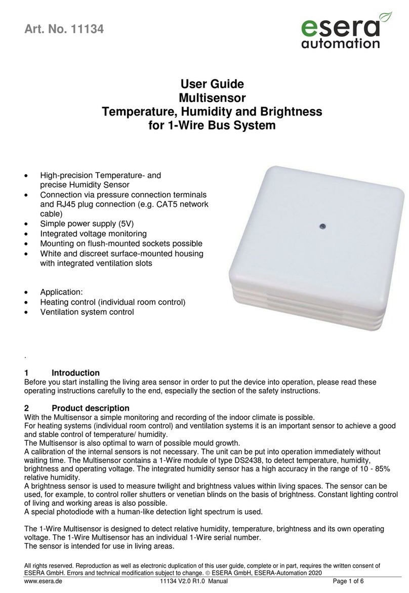
esera automation 11134 User manual

