esera ECO 501 PRO User manual

Art. No. 11607-24
*If the sensor or actuator supports Auto-E-Connect. For details, refer to the operating instructions of the sensor or actuator.
All rights reserved. Reprinting, including excerpts, not permitted without the express consent of ESERA GmbH.
Subject to technical changes. ESERA GmbH 2023
www.esera.de 11607-24 V1.0 R1.2 Manual Page 1 from 21
OPERATING INSTRUCTIONS
ECO 501 PRO
INDUSTRIAL SENSOR GATEWAY
of the 3rd generation for the 1-Wire bus system
HIGHLIGHTS
Fully automatic PLUG and PLAY
system for up to 30 sensors
⎯
Web server and access point
for configuration, debug and firmware
updates
⎯
Data interface for
Modbus/TCP, MQTT and ASCII
⎯
Auto-E-Connect Plug and Play
Level I to III
⎯
Fast readout of all devices
in 5 seconds cycle
⎯
Low maintenance industrial unit,
because without Linux. Native
programmed without unknown
libraries
⎯
LAN interface
for data, configuration, debug
and firmware updates
⎯
Extended temperature range
-5°C to 50°C
⎯
Rugged industrial design
⎯
Extensive protection circuits and good
device protection
⎯
Simple assembly

*If the sensor or actuator supports Auto-E-Connect. For details, refer to the operating instructions of the sensor or actuator.
All rights reserved. Reprinting, including excerpts, not permitted without the express consent of ESERA GmbH.
Subject to technical changes. ESERA GmbH 2023
www.esera.de 11607-24 V1.0 R1.2 Manual Page 2 from 21
1PRODUCT DESCRIPTION ...................................................................................................................3
2INDUSTRIAL ENVIRONMENT FOR THE ECO 501 SENSOR GATEWAY.........................................3
3ECO GATEWAY SYSTEM....................................................................................................................4
4THE ECO GATEWAY CONCEPT HAS THE FOLLOWING KEY POINTS..........................................4
5INTERFACE / INTERFACE AND 1-WIRE SECTION...........................................................................4
6ECO GATEWAY CONSTRUCTION......................................................................................................4
7AUTO-E-CONNECT® SUPPORT.........................................................................................................6
8AUTO-E-CONNECT SYSTEM ..............................................................................................................6
9TECHNICAL DATA...............................................................................................................................7
10 ENVIRONMENTAL CONDITIONS........................................................................................................8
11 CONFORMITY.......................................................................................................................................8
12 DISPLAY LED .......................................................................................................................................8
13 CONNECTION PLAN............................................................................................................................9
14 CONNECTION EXAMPLE ..................................................................................................................10
15 ACTIVATE ACCESS POINT...............................................................................................................11
16 SELECT ACCESS POINT...................................................................................................................12
17 CALL WEB SERVER VIA WIFI ..........................................................................................................12
18 CALL WEBSERVER VIA LAN............................................................................................................13
19 WEBSERVER, LOGIN ........................................................................................................................13
20 CONNECTION EXAMPLE 1-WIRE MULTISENSORS...FEHLER! TEXTMARKE NICHT DEFINIERT.
21 DATA INTERFACE, ASCII PROTOCOL............................................................................................14
22 ESERA ASCII TEXT PROTOCOL ......................................................................................................14
23 MODBUS /TCP PROTOCOL ..............................................................................................................15
24 MQTT PROTOCOL .............................................................................................................................17
25 YOUR PROTOCOL NOT THERE?.....................................................................................................17
26 1-WIRE NETWORK CABLING ...........................................................................................................18
27 FIRMWARE UPDATE .........................................................................................................................18
28 RECOVERY FUNCTION.....................................................................................................................19
29 RESET BUTTON.................................................................................................................................19
30 EXAMPLES FOR CODESYS / WAGO INTEGRATION .....................................................................19
31 EXAMPLES FOR SIEMENS SPS INTEGRATION.............................................................................19
32 OPERATING CONDITIONS................................................................................................................19
33 ASSEMBLY.........................................................................................................................................20
34 DISPOSAL...........................................................................................................................................20
35 SAFETY INSTRUCTIONS...................................................................................................................20
36 WARRANTY........................................................................................................................................20
37 WARNING ...........................................................................................................................................20
38 CONTACT ...........................................................................................................................................21
NOTE
Before you start installing the ECO 501 PRO and put the device into operation, read this operating
manual through to the end at your leisure, especially the section on safety instructions.
Supplementary documents and software:
•You perform many settings and configurations of the gateway with the help of the
Config Tool 3 software.
•Interface manual
•Modbus Interfaces Manual
All supplementary information can be found on our website (www.esera.de), under Download Area /
Technical Downloads.

Art. No. 11607-24
*If the sensor or actuator supports Auto-E-Connect. For details, refer to the operating instructions of the sensor or actuator.
All rights reserved. Reprinting, including excerpts, not permitted without the express consent of ESERA GmbH.
Subject to technical changes. ESERA GmbH 2023
www.esera.de 11607-24 V1.0 R1.2 Manual Page 3 from 21
1 PRODUCT DESCRIPTION
The ECO 501 gateway represents a powerful sensor interface of the latest generation for machine, plant and
system monitoring. The gateway has an access point and web server.
Up to 30 sensors can be connected to the ECO 501 fully automatically via Industrial 1-Wire Bus using the
Auto-E-Connect Plug and Play system.
The ESERA Auto-E-Connect system, which is an extension of the 1-Wire Bus standard, has been registered
as a European patent by ESERA GmbH.
A wide range of sensors is available, such as temperature, humidity, dew point, air quality (CO2, VOC or fine
dust), digital alarm signalling contacts, glass breakage and smoke detectors.
The ECO 501 provides for configuration, software updates, sensor and production data of the connected
sensors conveniently via web server. The web server is accessible via LAN and the access point (activation
at the push of a button).
This system represents a low maintenance industrial device as no Linux is used. The gateway has been
programmed natively for many years and no unknown libraries are used.
Each of the maximum 30 sensors can supply up to 5 measured values and a total of up to 150 sensor data
to your control system or PLC.
Extensive software support
is available free of charge via Config Tool and ECO Dashboard 100.
Via WLAN and LAN interface it is possible to communicate with up to 3 data connections via Modbus/TCP,
MQTT, ASCII text protocol.
For reliable operation in an industrial environment, the gateway is supplied with 9-30VDC DC voltage.
2 INDUSTRIAL ENVIRONMENT FOR THE ECO 501 SENSOR GATEWAY

*If the sensor or actuator supports Auto-E-Connect. For details, refer to the operating instructions of the sensor or actuator.
All rights reserved. Reprinting, including excerpts, not permitted without the express consent of ESERA GmbH.
Subject to technical changes. ESERA GmbH 2023
www.esera.de 11607-24 V1.0 R1.2 Manual Page 4 from 21
3 ECO GATEWAY SYSTEM
Many sensors, powerful interface and access point
4 The ECO Gateway concept has the following key points
•A large number of sensors can be
taught-in fully automatically via Industrial 1-Wire Bus
using Auto-E-Connect.
•Up to 30 sensors with a maximum of 150 sensor values can be connected.
•In addition, there are direct analog and digital inputs of the ECO Gateway.
•Furthermore, there is a housing interior climate monitoring system with limits and alarm system
•Extremely powerful data interface for up to 5 simultaneous data connections to control rooms and
PLC controllers
•Modern settings of the device via web server
•Connectable access point for independent access by mobile devices such as smartphones, tablets
or laptops.
5 INTERFACE / INTERFACE AND 1-WIRE SECTION
The basic structure of all ESERA ECO gateways is such that the devices consist of two sections.
These sections consist of an I/O section / gateway (1-Wire bus, eBus and/or sensor unit) and a very powerful
interface, hereinafter referred to as Maxi Interface.
The two sections communicate with each other internally.
These two sections are built into separate, electronic units on a gateway basis.
The advantage is that each of the sections is specially optimized for its task. This gives you an extremely
powerful, robust unit with low energy consumption. The
ECO Gateway are designed
for years of use.
No Linux is used in either section. These sections are natively programmed and
thus very low-maintenance. The advantage here is clearly the years of use without updates.
Depending on the ECO gateway, different I/O functions, e.g. 1-Wire or eBus and different
interfaces, e.g. Ethernet, WLAN, NB-IoT, LoRaWAN, are available.
6 ECO GATEWAY CONSTRUCTION
DATA INTERFACE
The ECO Gateway has an Ethernet interface with 10/100Mbit speed.
Various data protocols are supported via TCP/IP or UDP.
Up to 3 data connections and protocols + web server can be used simultaneously.
MODBUS PROTOCOL
The Modbus/TCP addressing of the gateway is clearly structured comparable to many other Modbus
systems. Addresses for system and device data are available.
We provide an address overview with all available data points via the download area of our website and
within the configuration software ESERA Config Tool 3.
MQTT PROTOCOL

Art. No. 11607-24
*If the sensor or actuator supports Auto-E-Connect. For details, refer to the operating instructions of the sensor or actuator.
All rights reserved. Reprinting, including excerpts, not permitted without the express consent of ESERA GmbH.
Subject to technical changes. ESERA GmbH 2023
www.esera.de 11607-24 V1.0 R1.2 Manual Page 5 from 21
An MQTT data connection is provided for OT and IoT applications. MQTT data is sent and received to a
broker.
You can set the send interval via web server. The sensor name is taken from the name field of the 1-Wire
sensors. If these are empty, default names are used. If you do not want an MQTT protocol, an additional
Modbus data connection can be provided via firmware update. Please ask for this at supp[email protected].
ASCII TEXT PROTOCOL The ECO 501 gateway outputs the 1-Wire sensor data ready prepared, e.g.
for temperature sensors
in C° cyclically. It is only necessary to divide by 100.
In addition, the article number for ESERA modules can be entered, the calculation and output is
adapted to the function of the module.
SENSORS AND ACTUATORS
Up to 30 sensors can be connected to the ECO 501 sensor gateway fully automatically via industrial 1-Wire
bus using the Auto-E-Connect Plug and Play system. Each of the maximum 30 sensors can supply up to 5
measured values and a total of up to 150 sensor data to your control system or PLC.
SELF-SUFFICIENT MANAGEMENT
The Sensor Gateway is intended for the autonomous management of a 1-Wire network. You no longer
need to worry about 1-Wire commands or formulas for evaluating the 1-Wire devices. The ECO 501
PRO gateway independently scans the 1-Wire network for new 1-Wire devices, reads their Auto-E-
Connect data, automatically adapts the device libraries* and outputs the adapted data in plain text,
adapted to the scanned 1-Wire devices.
DESIGNED FOR ALL 1-WIRE NETWORKS
The 1-Wire interface of the ECO 501 PRO is specially designed to
safely operate small to very large
1-Wire networks with long cable distances. 1-Wire devices can be operated simultaneously in mixed
parasitic or normal mode.
The strongest 1-Wire interface currently available has been developed for maximum data security,
even for complex network structures.
VOLTAGE SUPPLY
For power supply the ECO 501 has a wide range input of 12-24VDC (9-30 VDC) and is thus intended
for worldwide voltage system supplies.
Suitable DIN rail or plug-in
power supplies can be found in our webshop.
COMMISSIONING
Support videos for commissioning and configuration can be found on our website www.esera.de under
"Service and Support", Support Videos.
NOTE
Basics and tips on the 1-Wire bus system can be found in the ESERA Online Shop at
1-Wire Basics or please refer to our eBook in the store under Training/Documentation.

*If the sensor or actuator supports Auto-E-Connect. For details, refer to the operating instructions of the sensor or actuator.
All rights reserved. Reprinting, including excerpts, not permitted without the express consent of ESERA GmbH.
Subject to technical changes. ESERA GmbH 2023
www.esera.de 11607-24 V1.0 R1.2 Manual Page 6 from 21
7 AUTO-E-CONNECT® SUPPORT
The ECO 501 PRO 1-Wire gateway supports Auto-E-Connect Level I, II and III.
8 AUTO-E-CONNECT SYSTEM
With the launch of ECO Gateway, the ESERA Auto-E-Connect® 1-Wire Plug and Play system for the
1-Wire bus is now introduced and supported.
This means that fully automatic configurations of the 1-Wire devices* (sensors and actuators) are now
possible on the
1-Wire bus possible. It is optimized for commercial and industrial applications and enables significant
added value beyond sensor and chip data.
The Auto-E-Connect function is built up in three levels. The following levels are currently available
Level I, Level II and Level III are available.
With Auto-E-Connect Level III, fully automatic configurations of the 1-Wire devices on the
1-Wire bus is possible. It is optimized for industrial and IoT applications and enables significant added
value beyond sensor and chip data.
The Auto-E-Connect function automatically detects ESERA devices, starts suitable libraries and outputs
ready-formatted data.
The Auto-E-Connect functionality will be available for the ECO Gateway and ESERA-Station 200 Pro
from 2021.
Auto-E-Connect Level I
OWD Detect: Detect new sensors* and actuators* and automatically start customized libraries
Auto-E-Connect Level II
Visualization of product data: Readout and visualization of Auto-E-Connect and manufacturer data of
sensors* and actuators*, such as part number, date of manufacture, firmware and hardware version.
Auto-E-Connect Level III
Advanced Plug and Play System for 1-Wire Bus
oPRE CONFIGURATION
The OWD number for the next installation can be written to the 1-Wire device*.
oAUTOMATIC POSITIONING
The device* logs on to each ECO gateway with Auto-E-Connect III with the new desired OWD number.
This automatic login works up to the maximum possible OWD number of the ECO gateway.
oSENSORFINDER FUNCTION
The ECO 501 PRO can activate a status LED within the ESERA 1-Wire Pro sensors*. The status LED
flashes or lights up permanently for a certain time. This makes the detection of a device in a 1-Wire
network much easier. A faster detection saves a lot of time and therefore money when searching for a
1-Wire device.
oCLASSES ASSIGNMENT
ESERA 1-Wire Devices are assigned to OWD classes with the same properties. This assignment
enables fully automatic visualization and data evaluation in control systems. A class list is available from
ESERA.
For further information on the ESERA Auto-E-Connect system, please refer to the ESERA website and
the ESERA Config Tool 3.
Auto-E-Connect is registered as a German and European patent by ESERA GmbH.
Art. No. 11607-24
*If the sensor or actuator supports Auto-E-Connect. For details, refer to the operating instructions of the sensor or actuator.
All rights reserved. Reprinting, including excerpts, not permitted without the express consent of ESERA GmbH.
Subject to technical changes. ESERA GmbH 2023
www.esera.de 11607-24 V1.0 R1.2 Manual Page 7 from 21
9 TECHNICAL DATA
Feature
•Web server for configuration of data connections
•Internal access point available via pushbutton for 30 minutes
•High performance Ethernet interface
•WLAN antenna internal
Data interfaces
•Ethernet (LAN): TCP/IP, UDP
•Industrial 1-Wire Bus (5V, 1-Wire Data and Ground (GND))
•Modbus/TCP (Ethernet 10/100MBit)
•Text protocol according to ASCII standard
Plug and Play System,
Auto E-connect
functions
- Automatic Positioning: Advanced Plug And Play system for fully
automatic positioning of the sensor / actuator in the ECO
Gateway
- Automatic library assignment: The appropriate library is
assigned fully automatically for the sensor
- Classes Assignment: Output OWD sensor class via ECO
gateway
- Electronic nameplate: output of part number, year of
manufacture, software version, software revision, hardware
version, OWD position, sensor finder function
- Pre Configuration: Programming of the desired OWD at the next
ECO gateway, storage of the OWD number.
- Sensorfinder Function: LED display for sensor identification. Let
the status LED on the sensor / actuator flash for identification.
Data, Firmware Update
and configuration
ESERA Config Tool 3
Software Support
Config Tool 3, ECO Dashboard 100
Supply voltage
Wide range 9-30VDC, universal 12VDC / 24VDC supply
Current consumption
max. 5W at 230VAC
Power supply RTC
Goldcap, buffering of the internal clock (RTC) in case of supply
voltage failure for approx. 2 days. In the event of a longer failure,
the RTC must be reset.
The Goldcap is charged after approx. 2 hours.
1-Wire interface
•Advanced 1-Wire bus functions with Plug and Play feature,
Auto-E-Connect system
•max. 30 1-Wire sensors or actuators
•Output voltage 5V, max. 500mA
Protection circuits
ESD, overvoltage and reverse polarity protection,
1-Wire Protector for 1-Wire interface (overvoltage protection up to
28VDC)
Connection
Push In plug-in terminals (up to 2.5qmm cable cross-section)
Voltage
Power supply, wide range, univ.l 12VDC / 24VDC (9-30VDC)
Isolation
Galvanic isolation between Ethernet and 1-Wire interface
Supported 1-Wire
devices
DS2401, DS1963, DS1990, DS1820, DS18S20, DS18B20, DS2413,
DS2438, DS2450, DS2408, DS2405, DS2406 (only423,
other chips on request.
We will be happy to support additional modules as an OEM product for
you.

*If the sensor or actuator supports Auto-E-Connect. For details, refer to the operating instructions of the sensor or actuator.
All rights reserved. Reprinting, including excerpts, not permitted without the express consent of ESERA GmbH.
Subject to technical changes. ESERA GmbH 2023
www.esera.de 11607-24 V1.0 R1.2 Manual Page 8 from 21
10 ENVIRONMENTAL CONDITIONS
Operating temperature
-5°C to +50°C, standard temperature range
Storage temperature
-5°C to +50°C, standard temperature range
Relative humidity
10% to 92% (non-condensing)
Room classification
Operate only in dry rooms
Protection class
IP20
Protection class
III
Dimensions
2TE, 32 x 90 x 70mm (WxHxD)
11 CONFORMITY
EN 50090-2-2
EN 61000-4-2, ESD
EN 61000-4-3, HF
EN 61000-4-4, Burst
EN 61000-4-5, Surge
EN 61000-6-1, Noise immunity
EN 61000-6-3, Interference radiation
RoHS
12 DISPLAY LED
The module has different display LEDs. The function of the displays is as follows
Display
Designation
Function
LED Green
PWR
Display for supply voltage
LED Green
DATA
•After switching on the device, the LED flashes 3x
•Flashes during 1-wire activity
•Flashes when sending data via the data interface
•Flashes very quickly when "KAL Receive" has been
activated and the "KAL messages" from the control
system are absent.
LED Green
LAN
LAN - network status LED
Lights up when LAN network connection
is established
Flashes when the interface is not activated
LED Green
WLAN
WLAN - Network Status LED
Lights up when WLAN network connection is established
Flashes when the WLAN access point is activated and a direct
connection is possible

Art. No. 11607-24
*If the sensor or actuator supports Auto-E-Connect. For details, refer to the operating instructions of the sensor or actuator.
All rights reserved. Reprinting, including excerpts, not permitted without the express consent of ESERA GmbH.
Subject to technical changes. ESERA GmbH 2023
www.esera.de 11607-24 V1.0 R1.2 Manual Page 9 from 21
13 CONNECTION PLAN
Module bottom
1-Wire Bus Interface
1 = Ground 1-Wire
2 = 1-Wire Data
3 = 5V output
Module top side power supply 10-
30VDC
12 = Minus supply voltage
21 = Plus supply voltage
Notice:
5 = Reset Button
NOTE
The module may only be operated at the voltages and under the ambient conditions specified for it. The
operating position of the device is arbitrary.
The modules may only be commissioned by a qualified electrician.
Carry out all work of the electrical connection without current!
For further information on the operating conditions, see the following instructions under "Operating
conditions".
NOTE
The FE connection of the ECO 501 PRO should be connected to ground potential (PE). This establishes a
functional ground.

*If the sensor or actuator supports Auto-E-Connect. For details, refer to the operating instructions of the sensor or actuator.
All rights reserved. Reprinting, including excerpts, not permitted without the express consent of ESERA GmbH.
Subject to technical changes. ESERA GmbH 2023
www.esera.de 11607-24 V1.0 R1.2 Manual Page 10 from 21
14 CONNECTION EXAMPLE
Connection example of the ECO 501 Sensor Gateway with many sensors
Art. No. 11607-24
*If the sensor or actuator supports Auto-E-Connect. For details, refer to the operating instructions of the sensor or actuator.
All rights reserved. Reprinting, including excerpts, not permitted without the express consent of ESERA GmbH.
Subject to technical changes. ESERA GmbH 2023
www.esera.de 11607-24 V1.0 R1.2 Manual Page 11 from 21
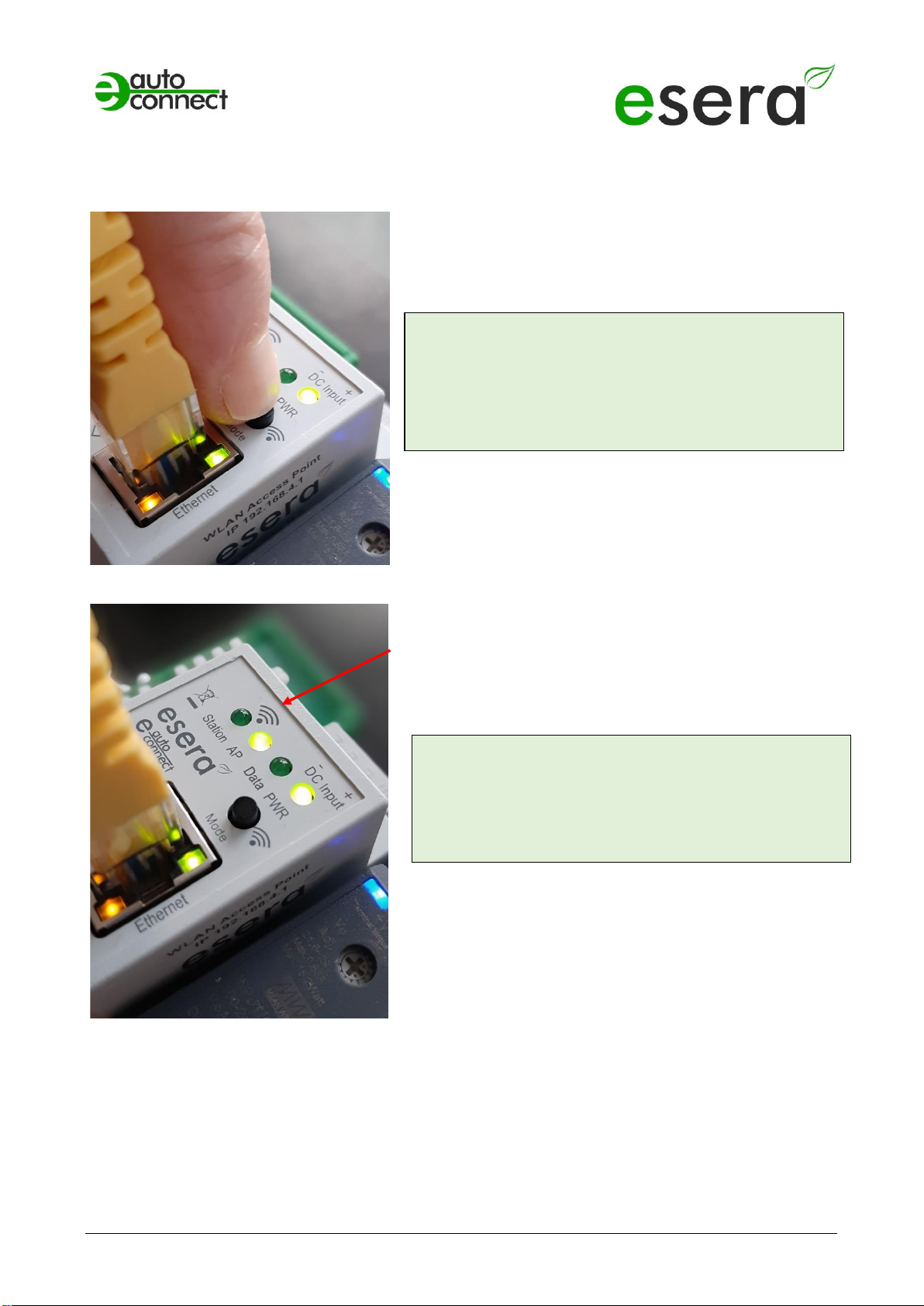
15 ACTIVATE ACCESS POINT
The ECO gateway with Maxi interface has a connectable WiFi (WLAN) access point.
This means that you can access the device via a mobile
device such as a smartphone, tablet or laptop. This is possible
directly - without additional devices via WiFi (WLAN), access
point (e.g. Fritzbox).
What is an access point? With an access point (wireless LAN
AP mode), mobile end devices such as laptops, tablets,
smartphones, etc. can be connected directly to the ECO
Gateway. No additional wireless LAN access point is required.
When the access point is activated, we talk about the AP
mode of the WLAN interface of the ECO Gateway.
(See figure, LED "AP" is on, LED "Station" is off)
If you no longer need the access point, switch it off by
pressing the button again for at least 5 seconds.
Push button to activate the Access Point
NOTE
You activate the access point by pressing (for 5 seconds)
the button on the top.
The access point is active for approx. 30 minutes. After
that, it deactivates automatically for security reasons.
You can switch off the access point by pressing it again
for at least 5 seconds.
NOTE
The web server is continuously available via the
Ethernet interface. You can reach it via the
IP address of the device.
The IP address of the ECO Gateway can be found on
the "Ethernet Interface Settings" web page
Access Point is activated

*If the sensor or actuator supports Auto-E-Connect. For details, refer to the operating instructions of the sensor or actuator.
All rights reserved. Reprinting, including excerpts, not permitted without the express consent of ESERA GmbH.
Subject to technical changes. ESERA GmbH 2023
www.esera.de 11607-24 V1.0 R1.2 Manual Page 12 from 21
16 SELECT ACCESS POINT
The ECO gateway with Maxi interface registers as a WLAN access point with the identifier "ESERA". In the
delivery state, the Ethernet interface is set to "DHCP".
The access point is open, executed without access password.
17 CALL WEB SERVER VIA WIFI
If you have connected to the WLAN network "ESERA", the web browser starts directly on many
smartphones.
If this is not the case, switch to your web browser (e.g. Firefox, Chrome, etc.) and enter
enter the IP address of the ECO Gateway. Now the web server of the ECO Gateway should be visible,
comparable to the following picture.
The configuration of the device is currently only possible via
the web server of the ECO Gateway.
NOTE
The IP address of the ECO Gateway via Access
Point is: 192.168.4.1
The IP address of the access point is printed on the
right side of the gateway housing.
Important:
Enter the IP address without "https://".
Select "ESERA" Access Point
NOTE
The ECO WLAN access point can be found as a
WLAN network at the identifier "ESERA".

Art. No. 11607-24
*If the sensor or actuator supports Auto-E-Connect. For details, refer to the operating instructions of the sensor or actuator.
All rights reserved. Reprinting, including excerpts, not permitted without the express consent of ESERA GmbH.
Subject to technical changes. ESERA GmbH 2023
www.esera.de 11607-24 V1.0 R1.2 Manual Page 13 from 21
18 CALL WEBSERVER VIA LAN
You can also connect the web server of the ECO Gateway at any time via LAN interface using the set
Reach IP address.
The IP address of the ECO Gateway is shown on the device display (if the device has a display). If the
device does not have a display, you can
also read out the current IP address (not the
IP address of the access point) via your router/DHCP server.
19 WEBSERVER, LOGIN
Password, LogIn
To be able to log into the web server of the ECO
Gateway, use for the first login the
Startup/default password: eserapwd
For security reasons, the password is not displayed in
plain text, but with dots.
After entering the password, click on the "Login"
button to open the main menu (hereinafter referred to
as the main menu).
Please change the password after the first login,
otherwise unauthorized persons can also
make settings on the
ECO Gateway.
Please enter a new and secure password via the
main menu/"Change Password".
Advice on how to assign secure passwords can be
found on the Internet.
Software version Ethernet interface/LogOut
Display of the software version of the Ethernet
interface installed on the device. The version of the 1-
Wire firmware can be seen via the Config Tool 3.
Click on the "LogOut" button to exit the web interface.
NOTE
The startup/default password for login is: eserapwd
IMPORTANT
Please change the password after the first login.
For more details about functions of the web server, please refer to the document
"Interface Manual" that you can find via our website www.esera.de, download area/technical-
downloads.
*If the sensor or actuator supports Auto-E-Connect. For details, refer to the operating instructions of the sensor or actuator.
All rights reserved. Reprinting, including excerpts, not permitted without the express consent of ESERA GmbH.
Subject to technical changes. ESERA GmbH 2023
www.esera.de 11607-24 V1.0 R1.2 Manual Page 14 from 21
20 DATA INTERFACE, ASCII PROTOCOL
You configure the Ethernet interface with the help of the Windows ESERA program Config Tool 3. You
find this program in the download area of the ESERA Onlineshop Tool 3 software.
21 ESERA ASCII TEXT PROTOCOL
The ASCII protocol is a standard protocol for the transmission of data via serial interfaces between a
computer and another device, such as an ECO Gateway and a controller.
The abbreviation "ASCII" stands for "American Standard Code for Information Interchange" and refers to the
code used to represent letters, numbers and other characters in digital form.
The ASCII protocol sends data in the form of ASCII strings, which can consist of a number of characters,
including letters, numbers, punctuation marks, and control characters. These strings are usually divided into
specific fields or segments to represent different types of data, e.g. measured values, status messages or
commands.
The ASCII protocol is relatively simple and easy to implement because it relies on standardized ASCII
characters and allows data to be transmitted in plain text.
Overall, the ASCII protocol is frequently used in applications that require simple, reliable and easy-to-
understand data transmission, such as our EC and ECO gateways that provide sensor and actuator data for
measurement and control technology or industrial automation.
The ECO 501 PRO provides two protocols. For configuration and analysis, the ESERA text protocol in ASCII
format can be used very easily. Here, special emphasis was placed on good readability and traceability. The
ESERA text protocol works with "GET" and "SET" commands, which probably every programmer has
already used in his own projects.
The ESERA text protocol is disclosed and documented. The current version of the ESERA protocol
description can be found in the programming manual in the download area of the article and the ESERA
Config Tool 3.
By default, port 5000 is preset for the ASCII protocol.
Art. No. 11607-24
*If the sensor or actuator supports Auto-E-Connect. For details, refer to the operating instructions of the sensor or actuator.
All rights reserved. Reprinting, including excerpts, not permitted without the express consent of ESERA GmbH.
Subject to technical changes. ESERA GmbH 2023
www.esera.de 11607-24 V1.0 R1.2 Manual Page 15 from 21
22 MODBUS /TCP PROTOCOL
Modbus/TCP is a protocol for communication between devices in a network, based on the Modbus protocol
and the TCP/IP protocol.
Modbus is a serial-based protocol that is widely used in industrial automation to transmit measurement data,
control commands, and status messages.
It is also widely used in computer network technology and is used to connect devices in a network.
Modbus/TCP provides a way to integrate Modbus-based devices into Ethernet-based networks by
embedding Modbus data packets into TCP/IP data packets. It uses the standard port number 502 for this.
The protocol works with two types of packets: Requests and responses. A request is sent from one device to
another to retrieve data or send commands. The response contains the data or confirmation that the
command has been executed.
It also supports various functions, including reading and writing data registers, reading input registers, and
reading and writing lock bits.
Modbus/TCP provides an effective and reliable way to exchange data between different devices on a
network and is used in many different applications in industrial automation, building automation and other
fields.
You can communicate with the ECO 501 PRO simultaneously via several data connections using the
Modbus TCP protocol.
For the Modbus TCP data connections the ports 502, 503, 504, 505 and 506 are preset.
Up to 10 simultaneous data connections are possible per port. In total, the number is to be limited to 20 data
connections. The IP address is preset to DHCP operation.
The Modbus protocol has a standardized structure. The following is a small excerpt of the addressing
overview.
The complete Modbus addressing overview can be found in the programming manual in the download area
of the ECO 501 PRO and within the Config Tool 3 software.
Excerpt Modbus address description
Description
Reading address
Word count
(16bit)
Data type
Gateway no.
60000
1
Word
Item no.
60001
1
Word
Firmware version
61000
5
String
Hardware version
61010
3
String
Serial number
61020
9
String
Time
61030
4
String
Date
61035
4
String
...
NOTE
Per Modbus TCP up to 10 connections are allowed per port, but in total the number is to be limited to
max. 20 connections.
The IP address is preset to DHCP operation.
NOTE
The configuration options for the Modbus/TCP protocol of the ECO501 can be found in the document
"Interface Manual", which you can find via our website www.esera.de, download area/technical
downloads

*If the sensor or actuator supports Auto-E-Connect. For details, refer to the operating instructions of the sensor or actuator.
All rights reserved. Reprinting, including excerpts, not permitted without the express consent of ESERA GmbH.
Subject to technical changes. ESERA GmbH 2023
www.esera.de 11607-24 V1.0 R1.2 Manual Page 16 from 21
1-Wire Bus Sensors
and Actuators
OWD 1, 1-Wire module
40100
1
Integer
40101,40102
2
Dword 1
40103,40104
2
Dword 2
40105,40106
2
Dword 3
40107,40108
2
Dword 4
40109,40110
2
Dword 5
40111,40112
2
Dword 6
40113,40114
2
Dword 7
40115,40116
2
Dword 8
OWD 2, 1-Wire module
40200
1
Integer
40201,40202
2
Dword 1
40203,40204
2
Dword 2
...

Art. No. 11607-24
*If the sensor or actuator supports Auto-E-Connect. For details, refer to the operating instructions of the sensor or actuator.
All rights reserved. Reprinting, including excerpts, not permitted without the express consent of ESERA GmbH.
Subject to technical changes. ESERA GmbH 2023
www.esera.de 11607-24 V1.0 R1.2 Manual Page 17 from 21
23 MQTT PROTOCOL
MQTT (Message Queuing Telemetry Transport) is a protocol for the transmission of messages between
devices in a network. MQTT is particularly suitable for transmitting data over a poor or intermittent network
connection, such as NB-IoT* (4G data radio), as it requires very little network bandwidth and resources.
The operation of MQTT is based on the publish-subscribe
pattern. A device (e.g., ECO gateway) can publish (publish) a message to a specific topic, and other devices
interested in that topic can receive (subscribe) that message.
A topic is a hierarchical system of names separated by slashes (/).
An example of a topic might be "home/livingroom/temperature", where "home" is the main topic, "livingroom"
is a subtopic of "home", and "temperature" is a subtopic of "livingroom".
MQTT uses a broker** that acts as an intermediary between devices. When a device publishes a message,
it is sent to the broker. The broker then checks which other devices are interested in that topic and sends the
message to all subscribers.
MQTT is a very efficient protocol because it requires minimal overhead communication between devices.
The
connection between devices is maintained by the device periodically sending
a "heartbeat" message to the broker to indicate its availability.
Overall, MQTT is a very flexible and scalable solution for transmitting data on a network, especially for IoT
(Internet of Things) applications.
Further details on MQTT can be found, for example, on Wikipedia, https://de.wikipedia.org/wiki/MQTT.
MQTT, data output via broker and clients
A broker is basically required for the operation of the MQTT protocol.
24 YOUR PROTOCOL NOT THERE?
The ECO 501 PRO is extremely powerful due to the Maxi data interface used. We can also integrate other
interface protocols on request. We would be happy to provide you with a quotation for this. Contact us via
technical support, support@esera.de.
MQTT Broker
for example Mosquitto
MQTT Client
Dashboard or MQTT
Explorrer
NOTE
The configuration options for the MQTT protocol of the ECO501 can be found in the document
"Interface Manual", which you can find via our website www.esera.de, download area/technical
downloads.
*If the sensor or actuator supports Auto-E-Connect. For details, refer to the operating instructions of the sensor or actuator.
All rights reserved. Reprinting, including excerpts, not permitted without the express consent of ESERA GmbH.
Subject to technical changes. ESERA GmbH 2023
www.esera.de 11607-24 V1.0 R1.2 Manual Page 18 from 21
25 1-WIRE NETWORK CABLING
The special feature of the 1-Wire system is the "BUS technology". All devices (sensors and actuators) are
operated in parallel on a three-wire cable, which is used for both power supply and data communication. The
1-Wire bus system joins the list of other successful bus systems, such as CAN or Modbus RTU. All of the
installation principles recommended for these are also applicable and applicable for 1-Wire.
The maximum size of a 1-Wire network is determined by various factors. These are mainly:
- Cable length in total and cable type
- Number of 1-Wire Devices
- Installation type of cable laying (topology)
- Number and design of cable connectors (unnecessary connection transitions are to be avoided)
All factors in total are summarized and designated as 1-Wire bus load. Each increase in a factor increases
the total 1-Wire bus load for the 1-Wire gateway and thus reduces the maximum network size.
According to our many years of experience and a lot of feedback from customers, the following conservative
recommendation can be made:
- Cable distances maximum 50 -120m
- Number of 1-Wire Devices not more than 20 -22 pieces
- As linear a topology as possible without T-junctions
The topology in particular plays a major role. If possible, it should be installed in linear topology. The linear
topology can be compared like pearls on a pearl necklace. The data line should be laid from one device to
the next without T-joints.
Furthermore, you can also name the type of cable used here. We recommend for the cabling
CAT5 or CAT6 network cable to be used. It is also possible to use J-Y(St)Y telephone cables and KNX
cables. Longer cable runs are possible with CAT5 versus CAT7 cables.
With twisted-pair cable, a greater connection length can be achieved in an undisturbed environment, since
the capacitive bus load is lower. A total length of 50 m and more can be easily achieved without additional
measures.
In disturbed, commercial and industrial environments, the cable should always be shielded to increase the
"robustness" or interference sensitivity of the system.
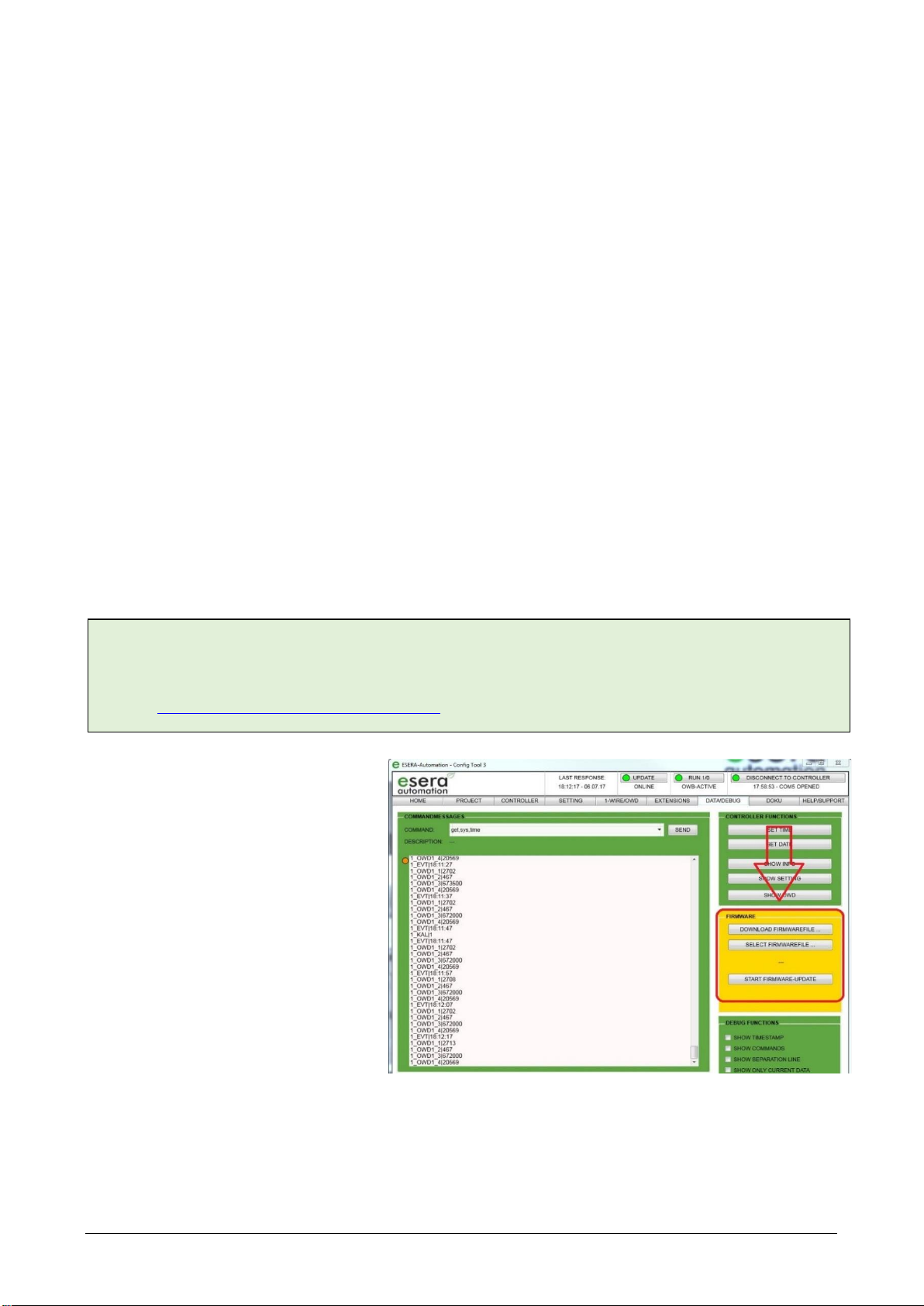
26 FIRMWARE UPDATE
The current device software (firmware)
can be found in the download area of
Config Tool 3.
When commissioning the ECO 501 PRO,
please check for a new firmware version.
Please always use the latest version.
You can update the firmware via the
web server.
Alternatively, you can also perform a
firmware update via Config Tool 3.
However, the update via web server is
preferred.
Please refer to the operating instructions
for Config Tool 3, which can be
found within Config Tool 3
under the "HELP/SUPPORT" tab.
NOTE
The above statements about 1-Wire are hints and tips and do not describe any product feature or represent
any guaranteed product feature of the ECO 501 PRO.
Information on basic principles and tips on the 1-Wire bus system can also be found in the ESERA Online
Shop at https://www.esera.de/1-wire-grundlagen/.

Art. No. 11607-24
*If the sensor or actuator supports Auto-E-Connect. For details, refer to the operating instructions of the sensor or actuator.
All rights reserved. Reprinting, including excerpts, not permitted without the express consent of ESERA GmbH.
Subject to technical changes. ESERA GmbH 2023
www.esera.de 11607-24 V1.0 R1.2 Manual Page 19 from 21
You can find a video about the firmware update on our website under "Service and Support, Support
Videos".
27 RECOVERY FUNCTION
If the update is faulty, e.g. due to a power failure during the update,
you can use the recovery function. To do this, press and hold the
reset button (this is located under hole 5 on the top of the module),
start the update in ConfigTool 3 and release the reset button after
approx. 1 second after starting in ConfigTool -3. Now the update
should start.
If you have any problems with the installation, we will be happy to
help you. Simply contact our support team by e-mail at
28 RESET BUTTON
The restart or also called RESET is performed via the RESET button of the system. When the button is
pressed, the device is restarted. The permanently stored data is retained, but all connections are
interrupted.
This keystroke does not correspond to an interruption (also called cold start) of the power supply.
29 EXAMPLES FOR CODESYS / WAGO INTEGRATION
We will be happy to provide you with test software for integrating the ECO 501 PRO into the PLC software
Codesys/WAGO. For this purpose, please contact our technical support at support@esera.de.
30 EXAMPLES FOR SIEMENS SPS INTEGRATION
Since many years the Modbus TCP protocol is also available in the programming environment of Siemens
PLCs. The used Modbus addresses of the ECO 501 PRO were adapted to the requirements of the Siemens
programming environment. Therefore, this combination is also possible and has already been implemented
by many customers.
31 OPERATING CONDITIONS
The module may only be operated at the voltages and under the ambient conditions specified for it. The
operating position of the device is arbitrary. The device is intended for use in dry and dust-free rooms. Do not
operate the module in an environment where flammable gases, vapors or dusts are or could be present.
If condensation forms, wait for an acclimatization period of at least 2 hours.
The modules may only be commissioned by a qualified electrician.
NOTE
Please also refer to the operating instructions for Config Tool 3, which can be found within Config
Tool 3 under the "HELP/SUPPORT" tab.
Furthermore you can find a video about the firmware update on our website under "Service and Support,
Support Videos".
NOTE
After performing a firmware update, we recommend
disconnecting the gateway from the power supply for approx. 30
seconds and restarting it.

*If the sensor or actuator supports Auto-E-Connect. For details, refer to the operating instructions of the sensor or actuator.
All rights reserved. Reprinting, including excerpts, not permitted without the express consent of ESERA GmbH.
Subject to technical changes. ESERA GmbH 2023
www.esera.de 11607-24 V1.0 R1.2 Manual Page 20 from 21
32 ASSEMBLY
The mounting location must be protected from moisture. The device may only be used in dry rooms. The
device is intended for mounting inside a control cabinet as a stationary device.
33 DISPOSAL
Do not dispose of the device in household waste! Electronic devices are to be disposed of
according to of the Directive on Waste Electrical and Electronic Equipment on the local
Collection points for electronic waste to dispose of!
34 SAFETY INSTRUCTIONS
When handling products that come into contact with electrical voltage, the applicable VDE regulations
must be observed, in particular VDE 0100, VDE 0550/0551, VDE 0700, VDE 0711 and VDE 0860.
•All connection and wiring work may only be carried out when the device is de-energized.
•Before opening a device, always disconnect the power plug or ensure that the device is de-energized.
•Components, assemblies or devices may only be put into operation if they have previously been installed in a
housing so that they are safe to touch. They must be de-energized during installation.
•Tools may only be used on devices, components or assemblies if it has been ensured that the devices are
disconnected from the supply voltage and that electrical charges stored in the components located in the device
have been discharged beforehand.
•Live cables or lines to which the device, component or assembly is connected must always be inspected for
insulation faults or breaks.
•If a fault is detected in the supply line, the device must be taken out of operation immediately until the defective
line has been replaced.
•When using components or assemblies, attention must always be drawn to strict compliance with the
characteristic data for electrical variables specified in the associated description.
•If it is not clear for the non-commercial end user from an existing description which electrical characteristic values
apply to a component or an assembly, how external wiring is to be carried out or which external components or
additional devices may be connected and which connection values these external components may have, a
qualified electrician must be consulted.
•Before commissioning a device, it must generally be checked whether this device or the assembly is
fundamentally suitable for the application for which it is to be used.
•In case of doubt, it is essential to consult specialists, experts or the manufacturer of the assemblies used.
•We do not accept any liability for operating and connection errors that are beyond our control.
•Kits should be returned with a precise description of the fault and the associated assembly instructions without
housing in the event of malfunction. Without error description a repair is not possible. We have to charge extra
for time-consuming assembly or disassembly of housings.
•It is essential that the relevant VDE regulations are observed during installations and when handling parts that
will later carry mains voltage.
•Devices that are operated at a voltage greater than 35 VDC/ 12mA may only be connected and commissioned
by qualified electricians.
•Commissioning may only be carried out if the circuit is installed in a housing so that it is safe to touch.
•If measurements are unavoidable with the housing open, a safety isolating transformer must be connected
upstream or a suitable power supply unit must be used for safety reasons.
•After installation, the required test must be performed in accordance with DGUV Regulation 3.
35 WARRANTY
ESERA GmbH warrants that the goods sold are free from material and manufacturing defects at the time of transfer
of risk and have the contractually warranted characteristics. The statutory warranty period of two years from invoicing
applies. The warranty does not cover normal wear and tear. Claims of the customer for damages, e.g. due to non-
performance, culpa in contrahendo, breach of ancillary contractual obligations, consequential damages, damages in
tort and other legal grounds are excluded. ESERA GmbH shall be liable, however, in the absence of a warranted
characteristic, in the case of intent or gross negligence. Claims from the product liability law are not affected by this. If
defects occur for which ESERA GmbH is responsible, and if in case of exchange of the goods also the replacement
delivery is defective, the purchaser has the right to rescission or reduction of the purchase price. ESERA GmbH
assumes no liability neither for the constant and uninterrupted availability of ESERA GmbH nor for technical or
electronic errors of the online offer.
We are constantly developing our products and reserve the right to make changes and improvements to any of the
products described in this documentation without prior notice. If you need documentation or information on older
36 WARNING
All listed designations, logos, names and trademarks (including those that are not explicitly marked) are trademarks,
registered trademarks or other designations protected by copyright or trademark or title law of their respective owners
and are expressly recognized by us as such. The mention of these designations, logos, names and trademarks is for
Other manuals for ECO 501 PRO
1
Table of contents
Other esera Gateway manuals


Popular Gateway manuals by other brands

Fortinet
Fortinet FortiSandbox 1000D quick start guide

Vertiv
Vertiv Avocent Installer/user guide

lushSensor
lushSensor LS-GW-00-000W-01 user manual

FIBRO
FIBRO 2480.00.91.42 operating instructions

Iskratel
Iskratel Innbox V50-U Management guide

Lucent Technologies
Lucent Technologies PacketStar PSAX 20 user guide


