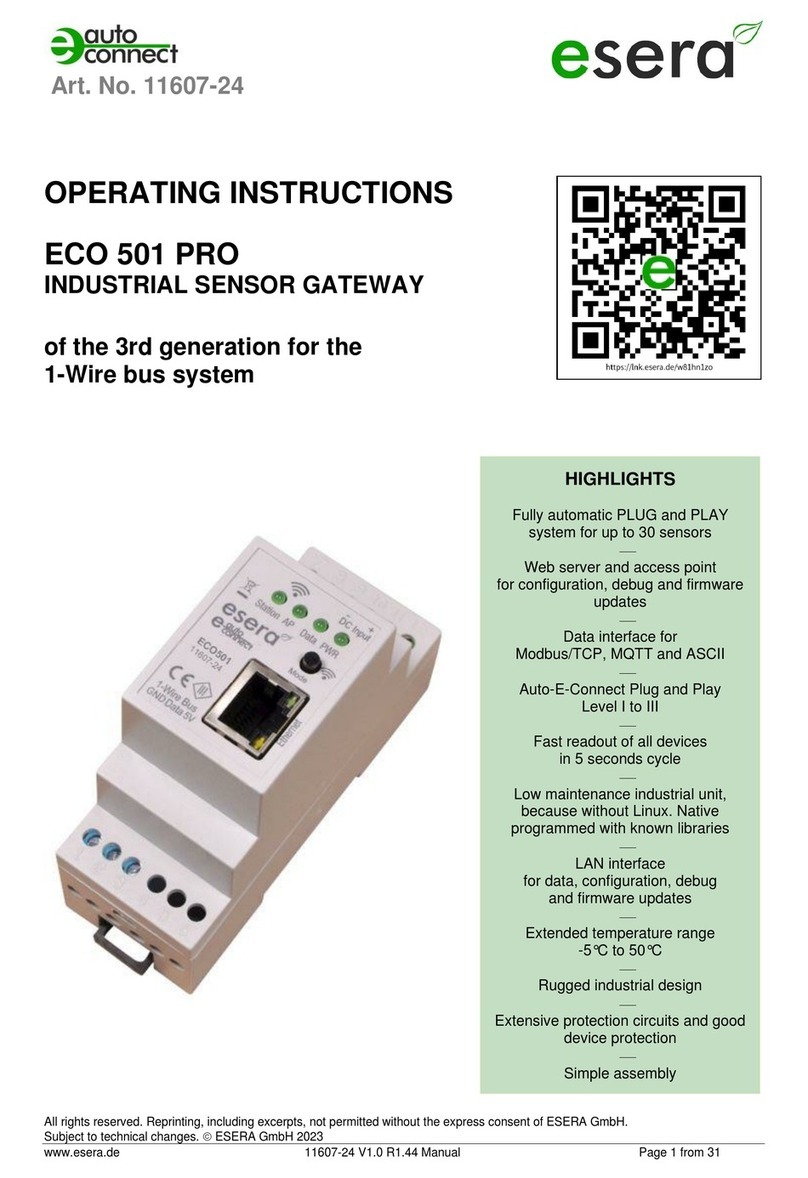
esera STATION 200 V2 User manual

All rights reserved. Reprinting, including excerpts, not permitted without the express consent of ESERA GmbH.
Subject to technical changes. ESERA GmbH, 2023
www.esera.de Interface-Manual Modbus V2.0 Page 1 from 26
Modbus/TCP, Modbus/RTU
INTERFACE MANUAL
ECO GATEWAYS AS OF YEAR OF MANUFACTURE 2023
WITH WEBSERVER
ESERA STATION 200 V2
ECO 110 SENSOR GATEWAY PRO
ECO 501 SENSOR GATEWAY PRO
ECO 502 SENSOR GATEWAY PRO
ECO 503 IT/IOT SWITCH
ECO 608 SENSOR GATEWAY 1-WIRE
UMS2205 ENVIRONMENTAL MONITORING STATION
V2.0 R1.2

All rights reserved. Reprinting, including excerpts, not permitted without the express consent of ESERA GmbH.
Subject to technical changes. ESERA GmbH, 2023
www.esera.de Interface-Manual Modbus V2.0 Page 2 from 26
1. CONTENTS
1. CONTENTS.........................................................................................................................................2
2. PRODUCT OVERVIEW ECO AND EC GATEWAYS ........................................................................3
3. MODBUS/TCP GENERAL .................................................................................................................4
4. MODBUS COMMUNICATION ECO GATEWAY ...............................................................................4
5. ECO GATEWAY SYSTEM .................................................................................................................5
6. THE ESERA ECO GATEWAY CONCEPT.........................................................................................5
7. INTERFACE (MAXI INTERFACE) - AND I/O SECTION....................................................................5
8. CONFIGURATION MODBUS INTERFACE.......................................................................................7
8.1. ACTIVATE ACCESS POINT...............................................................................................................7
8.2. SELECT ACCESS POINT...................................................................................................................8
8.3. CALLING THE WEB SERVER VIA WIFI.............................................................................................8
8.4. CALLING THE WEB SERVER VIA LAN..............................................................................................9
8.5. WEBSERVER, SIGN IN/LOG IN .........................................................................................................9
8.6. HOME/MAIN PAGE...........................................................................................................................10
9. MODBUS TEST SOFTWARE ..........................................................................................................11
10. MODBUS FUNCTION CODES.........................................................................................................12
11.MODBUS ADDRESSES...................................................................................................................14
11.1. MODBUS READ ADDRESSES, SYSTEM VARIABLES...................................................................14
11.2. MODBUS READ ADDRESSES 1-WIRE SENSORS /OWD.............................................................16
11.3. MODBUS READ ADDRESSES 1-WIRE TEMPERATURE SENSORS ............................................18
11.4. MODBUS READ ADDRESSES 1-WIRE ACTUATORS....................................................................19
11.5. MODBUS WRITE ADDRESSES.......................................................................................................21
11.6. MODBUS WRITE ADDRESSES 1-WIRE SENSORS.......................................................................22
11.7. MODBUS WRITE ADDRESSES 1-WIRE ACTUATORS ..................................................................24
12. CONCLUSION AND FEEDBACK ....................................................................................................26
13. WARRANTY .....................................................................................................................................26
14. WARNING.........................................................................................................................................26
15. CONTACT.........................................................................................................................................26

All rights reserved. Reprinting, including excerpts, not permitted without the express consent of ESERA GmbH.
Subject to technical changes. ESERA GmbH, 2023
www.esera.de Interface-Manual Modbus V2.0 Page 3 from 26
2. PRODUCT OVERVIEW ECO AND EC GATEWAYS
The ESERA EC and ECO gateways of the latest generation are divided into different series.
We offer the right device for different requirements and areas of application, such as private, commercial and
industrial use.
The following is an overview of the ECO and EC gateways.
All gateways have an access point and web server. Only the gateways with this equipment will be discussed
in this manual. In the following overview, the devices for this manual are marked in green.
For the gateways without web server and access point use the manual version 1.0.
ECO GATEWAY WITH MAXI INTERFACE,
MODBUS interface
AND ACCESS POINT AND WEBSERVER
Described below in this manual.
EC and ECO GATEWAY STANDARD
INTERFACE,
WITHOUT WEBSERVER
Not described in this manual
•ECO 110 Sensor Gateway 1-Wire Interface
•ECO 501 Pro, Sensor Gateway Modbus/TCP
MQTT, with 1-Wire Interface
•ECO 502 Pro, Sensor Gateway Modbus/RTU with
1-Wire Interface
•ECO 503, IT/IoT Switch Gateway, Modbus/TCP,
MQTT, 8-channel switching module 10/16A and
dig. inputs
•ECO 608 Pro, Security Sensor Gateway,
Modbus/TCP, MQTT, with 1-Wire Interface,
digital I/O
•UMS 2206 Pro, Smart City environmental
measurement system, wall mount, 8 environmental
sensors, UPS,
1-Wire interface, digital I/O
•1-Wire Gateway 10,
Smart Home Sensor Gateway,
with 1-Wire Interface
•1-Wire Gateway 20,
Smart Home Sensor Gateway,
with 1-Wire Interface Relay + analog Out
•ECO 100,
Smart Building Sensor Gateway with
1-Wire Interface

All rights reserved. Reprinting, including excerpts, not permitted without the express consent of ESERA GmbH.
Subject to technical changes. ESERA GmbH, 2023
www.esera.de Interface-Manual Modbus V2.0 Page 4 from 26
3. MODBUS/TCP GENERAL
Modbus/TCP is a protocol for communication between devices in a network, based on the Modbus protocol
and the TCP/IP protocol.
Modbus is a serial-based protocol that is widely used in industrial automation to transmit measurement data,
control commands, and status messages. It is
also widely used in computer network technology and is used to connect devices in a network.
The Modbus/TCP protocol allows to connect controllers and gateways in Ethernet networks by embedding
Modbus data packets into TCP/IP data packets. It uses the standard port number 502.
The protocol works with two types of packets: Requests and responses. A request is sent from one device to
another to retrieve data or send commands. The response contains the data or confirmation that the
command has been executed.
It also supports various functions, including reading and writing data registers, reading input registers, and
reading and writing lock bits.
Modbus/TCP provides an effective and reliable way to exchange data between different devices on a
network and is used in many different applications in industrial automation, building automation and other
fields.
4. MODBUS COMMUNICATION ECO GATEWAY
Modbus is de facto the common bus standard for communication between PLC machine controllers and the
machine-related environment in industry.
No PLC controller on the market can do without this bus interface. The success story of the Modbus
standard was initiated in 1979 by Gould-Modicon for communication with its programmable logic controllers.
In the industry, Modbus has become a standard because it is an open protocol. Since 2007, the Modbus
TCP version has been part of the IEC 61158 standard. (Source: https://de.wikipedia.org/wiki/Modbus)
ESERA has Modbus/TCP and Modbus/RTU as an integral part of the data interfaces of the ECO Gateway
product series, and can thus connect various industry standards, such as Modbus, MQTT, LoRaWAN, NB-
IoT and 1-Wire, via gateways.
During the development of the ECO sensor gateways, special emphasis was placed on user-friendliness and
many automatic functions. This is additionally supported by a configuration software,
Config Tool 3, which combines all desirable functions up to the documentation and an installation report.
By the ESERA gateways are intended for a wide range of applications, even far outside the industry
attractive. The application areas include all commercial applications, such as smart home, smart building,
data center, OT and IoT systems.

All rights reserved. Reprinting, including excerpts, not permitted without the express consent of ESERA GmbH.
Subject to technical changes. ESERA GmbH, 2023
www.esera.de Interface-Manual Modbus V2.0 Page 5 from 26
5. ECO GATEWAY SYSTEM
Many sensors, a powerful interface, a web server and access point, and a fully automated plug and play
system.
6. The ESERA ECO Gateway Concept
•A large number of sensors can be connect fully automatically via Industrial 1-Wire Bus
using Auto-E-Connect.
•Up to 30 sensors with a maximum of 150 sensor values can be connected.
•In addition, there are direct analog and digital inputs of the ECO Gateway.
•Furthermore, there is a housing interior climate monitoring system with alarm system.
•Extremely powerful data interface for up to 5 simultaneous data connections to control rooms and
PLC controllers
•Modern settings of the gateway via web server
•Connectable access point for independent access by mobile devices, such as smartphones, tablet or
laptop.
7. INTERFACE (MAXI INTERFACE) - AND I/O SECTION
The basic structure of all ESERA ECO gateways is such that the devices consist of two sections.
The first section consists of an I/O gateway (1-Wire bus, eBus and/or sensor unit) and
the second section consists of a very powerful interface. This very powerful interface is referred to below as
the Maxi Interface.
The two sections communicate with each other internally.
These two sections are built into separate, electronic units on a gateway basis.
The advantage is that each of the sections is specially optimized for its task. This gives you an extremely
powerful, robust device with low energy consumption. The
ECO gateways are designed for years of use.
No Linux system is used in either of the sections. All sections of the devices are natively programmed and
thus very low-maintenance.
The advantage here is clearly the years of use without any update.
Depending on the ECO gateway, different I/O functions, e.g. 1-Wire or eBus and different
interfaces, e.g. Ethernet, WLAN, NB-IoT, LoRaWAN, are available.

All rights reserved. Reprinting, including excerpts, not permitted without the express consent of ESERA GmbH.
Subject to technical changes. ESERA GmbH, 2023
www.esera.de Interface-Manual Modbus V2.0 Page 6 from 26
For the above reason, there are two firmware update buttons. Please avoid confusing the firmware versions.
Illustration:
Extract from the main page of the web
server

All rights reserved. Reprinting, including excerpts, not permitted without the express consent of ESERA GmbH.
Subject to technical changes. ESERA GmbH, 2023
www.esera.de Interface-Manual Modbus V2.0 Page 7 from 26
8. CONFIGURATION MODBUS INTERFACE
NOTE
The following description is intended for ECO Sensor Gateways from year of manufacture 2023 with
web server and access point. If you have a 1-Wire gateway without web server, please use the
interface manual Modbus V1.0
8.1. ACTIVATE ACCESS POINT The ECO Gateways with Maxi interface have a connectable
WiFi (WLAN) access point.
This means that you can access the device via mobile end
device, such as smartphone, tablet or laptop. This is possible
directly - without additional devices via WiFi (WLAN), access
point (e.g. Fritzbox).
What is an access point?
With an access point (wireless LAN AP mode), mobile end
devices such as laptop, tablet, smartphone, etc. can be
connected directly to the ECO Gateway. No additional
wireless LAN access point is required.
When the access point is activated, we talk about the AP
mode of the WLAN interface of the ECO Gateway.
(See figure, LED "AP" is on, LED "Station" is off)
If you no longer need the access point, switch it off by
pressing the button again for at least 5 seconds.
Push button to activate the Access Point
NOTE
You activate the access point by pressing
(of 5 seconds length) on the button on the top.
The access point is active for approx. 30 minutes. After
that, it deactivates automatically for security reasons.
You can switch off the access point by pressing the
button again for at least 5 seconds.
NOTE
The web server is continuously available via the
Ethernet interface. You can reach it via the
IP address of the device.
The IP address of the ECO gateway can be found on
the "Ethernet Interface Settings" web page
Access Point is activated

All rights reserved. Reprinting, including excerpts, not permitted without the express consent of ESERA GmbH.
Subject to technical changes. ESERA GmbH, 2023
www.esera.de Interface-Manual Modbus V2.0 Page 8 from 26
8.2. SELECT ACCESS POINT
The ECO gateway with Maxi interface registers as a WLAN access point with the identifier "ESERA". In the
delivery state, the Ethernet interface is set to "DHCP".
The access point is open, without an access password.
8.3. CALL WEB SERVER VIA WIFI
If you have connected to the WLAN network "ESERA", the web browser starts directly on many mobile
phones.
If this is not the case, switch to your web browser (e.g. Firefox, Chrome, etc.) and enter the IP address of the
ECO Gateway. Now the web server of the ECO Gateway should be visible, comparable to the following
picture.
The configuration of the device is currently only possible via
the web server of the ECO Gateway.
NOTE
The IP address of the ECO Gateway via Access
Point is: 192.168.4.1
The IP address of the access point is printed on the
right side of the gateway housing.
Important:
Enter the IP address without "https://".
Select "ESERA" Access Point
NOTE
The ECO WLAN access point can be found as a
WLAN network at the identifier "ESERA".

All rights reserved. Reprinting, including excerpts, not permitted without the express consent of ESERA GmbH.
Subject to technical changes. ESERA GmbH, 2023
www.esera.de Interface-Manual Modbus V2.0 Page 9 from 26
8.4. CALL WEBSERVER VIA LAN
You can also connect the web server of the ECO Gateway at any time via LAN interface using the set
Reach IP address.
The IP address of the ECO Gateway is shown on the device display (if the device has a display). If the
device does not have a display, you can
also read out the current IP address (not the
IP address of the access point) via your router/access point/DHCP server.
8.5. WEBSERVER, SIGN IN/LOG IN
Password, Sign in/Log in
To be able to log into the web server of the ECO
Gateway, use for the first login the
Startup/default password: eserapwd
For security reasons, the password is not displayed in
plain text, but with dots.
After entering the password, click on the "Log in"
button to open the main menu (hereinafter referred to
as the main menu).
Please change the password after the first login,
otherwise unauthorized persons can also make
settings on the
ECO Gateway.
Please enter a new and secure password via the
main menu/"Change Password".
Advice on how to assign secure passwords can be
found on the Internet.
Software version Ethernet interface/Log Out
Click on the "Log Out" button to exit the web
interface.
NOTE
The startup/default password for Log In is: eserapwd
IMPORTANT
Please change the password after the first login.

All rights reserved. Reprinting, including excerpts, not permitted without the express consent of ESERA GmbH.
Subject to technical changes. ESERA GmbH, 2023
www.esera.de Interface-Manual Modbus V2.0 Page 10 from 26
8.6. HOME/MAIN PAGE
The ECO gateways are delivered with different equipment regarding interfaces and protocols.
The main page is divided into two sections:
•General
Here you will find all menus for configuring the interfaces and viewing the gateway
and sensor data. The various buttons (selection
keys) take you to the corresponding submenus,
which are described below.
•Danger Zone
Here you get to submenus where you should take
great care, because the possible changes are
usually not undoable.
Ethernet Interface Setting
Use this button to enter the menu for setting the IP
address, Sub Net and Gateway number.
MQTT Settings (if supported by the device)
In this menu you can enter e.g. access data of the
MQTT broker.
ESERA ASCII Settings
From here you come to the submenu for setting the
data port. Pressing the button takes you to the menu for
configuring socket interfaces 2 - 5.
Modbus Settings
In this menu you can set e.g. the port number of the
Modbus/TCP interfaces.
Data View
Here you can view the gateway data and the sensors
connected via 1-Wire bus system. Here you will also
find the Auto-E-Connect information.
Firmware update, 1-Wire bus, I/O section
Using this button you can perform an update of the
Perform 1-Wire section.
Firmware Update Interface Section
This button allows you to perform a firmware update of
the interface and the web server.
Change Password
To change the password for the web server, click the
"Change Password" button.
Factory Reset
You may reset the Ethernet interface to the delivery
state. For this press the button "Factory Reset
Software version Ethernet interface/Log Out
Display of the software version of the Ethernet interface
installed on the device. The version of the 1-Wire
firmware can be seen via the Config Tool 3.
Sign Out
Click the "Sign Out" button to exit the web server.

All rights reserved. Reprinting, including excerpts, not permitted without the express consent of ESERA GmbH.
Subject to technical changes. ESERA GmbH, 2023
www.esera.de Interface-Manual Modbus V2.0 Page 11 from 26
9. MODBUS TEST SOFTWARE
To perform first tests via Windows and a small test program, you can use e.g. the program Modbus Master
(qmodmaster). It is an open source program. Below the link for the download.
https://sourceforge.net/projects/qmodmaster/
We do not take any liability for the link and the test program.

All rights reserved. Reprinting, including excerpts, not permitted without the express consent of ESERA GmbH.
Subject to technical changes. ESERA GmbH, 2023
www.esera.de Interface-Manual Modbus V2.0 Page 12 from 26
10. MODBUS FUNCTION CODES
Structure and function codes Modbus
RTU, RS485 interface
Structure and function codes
Modbus TCP, Ethernet interface
FC1,2 (reads single bits):
Example:
FC1,2 (reads single bits):
Example:
Gateway no.
1
Transactionsnr high
0
Function code
1
Transactionsnr low
0
Start address high (bit)
0
Protocol ident high
0
Start address low (bit)
32
Protocol ident low
0
Number of bits high
0
Bytes from here
6
Number of bits low
8
Recognition
e.g. 1
CRC high
x
Function code
1
CRC low
x
Start address high (bit)
0
Start address low (bit)
32
Number of bits high
0
Number of bits low
8
FC3,4 (reads words):
FC3,4 (reads words):
Gateway no.
1
Transactionsnr high
0
Function code
4
Transactionsnr low
0
Start address high (word)
238
Protocol ident high
0
Start address low (word)
102
Protocol ident low
0
Word count high
0
Bytes from here
6
Word count low
9
Recognition
e.g. 1
CRC high
x
Function code
4
CRC low
x
Start address high (word)
238
Start address low (word)
102
Word count high
0
Word count low
9
FC5 (sets one bit):
FC5 (sets one bit):
Gateway no.
1
Transactionsnr high
0
Function code
5
Transactionsnr low
0
Start address high (bit)
0
Protocol ident high
0
Start address low (bit)
32
Protocol ident low
0
Bit value high
255 or 0
Bytes from here
6
Bit value low
0
Recognition
e.g. 1
CRC high
x
Function code
5
CRC low
x
Start address high (bit)
0
Start address low (bit)
32
Bit value high
255 or 0
Bit value low
0
FC6 (writes a word):
FC6 (writes a word):
Gateway no.
1
Transactionsnr high
0
Function code
6
Transactionsnr low
0
Start address high (word)
1
Protocol ident high
0
Start address low (word)
146
Protocol ident low
0
Write value high
0
Bytes from here
6
Write value low
85
Recognition
e.g. 1
CRC high
x
Function code
6
CRC low
x
Start address high (word)
1
Start address low (word)
146
Write value high
0
Write value low
85

All rights reserved. Reprinting, including excerpts, not permitted without the express consent of ESERA GmbH.
Subject to technical changes. ESERA GmbH, 2023
www.esera.de Interface-Manual Modbus V2.0 Page 13 from 26
FC16 (writes words):
FC16 (writes words):
Gateway no.
1
Transactionsnr high
0
Function code
16
Transactionsnr low
0
Start address high (word)
238
Protocol ident high
0
Start address low (word)
102
Protocol ident low
0
Word count high
0
Bytes from here
11
Word count low
2
Recognition
e.g. 1
Byte count
4
Function code
16
Write value1 high
0
Start address high (word)
238
Write value1 low
123
Start address low (word)
102
Write value2 high
0
Word count high
0
Write value2 low
234
Word count low
2
CRC high
x
Byte count
4
CRC low
x
Write value1 high
0
Write value1 low
123
Write value2 high
0
Write value2 low
234

All rights reserved. Reprinting, including excerpts, not permitted without the express consent of ESERA GmbH.
Subject to technical changes. ESERA GmbH, 2023
www.esera.de Interface-Manual Modbus V2.0 Page 14 from 26
11. MODBUS ADDRESSES
NOTE: Only for ECO Sensor Gateways from year of manufacture 2023 with web server, e.g. ECO 501, ECO 502, ECO 608
11.1. MODBUS READ ADDRESSES, SYSTEM VARIABLES
Description
Reading addresses
Comment
Address
Word
Quantity
(16Bit)
Data
type
Bit
address
System inputs and outputs and sensors of the ECO Gateway
Binary inputs
Only:
Gateway 2,
Gateway 20
ECO 200
50001
1
Word
Status of the binary inputs of the 1-Wire Gateway 2 / 1-Wire Gateway 20
HHLL
Binary outputs
Gateway 2,
Gateway 20,
ECO 200
Outputs
50002
1
Word
32 to 36
Status of the binary outputs of the 1-Wire Gateway 2 / 1-Wire Gateway 20
HHLL
Analog output
Only:
Gateway 2,
Gateway 20
50003
1
Word
16 to 19
Status of the analog output of the 1-Wire gateway 2 / 1-Wire gateway 20
HHLL
Binary input or
output (optional)
ECO 100
ECO 200
50004 -
50009
1
Word
Status of binary / digital inputs or outputs, depending on the equipment of the
ECO gateways.
(For details see operating instructions of the respective ECO gateway)
HHLL
Sensor value 1-8
ECO 100,
ECO 200
50020 -
50029
1
Integer
Depending on the integrated sensor,
Temperature, rel. humidity, dew point, etc.
(For details see operating instructions of the respective ECO gateway)
HHLL

All rights reserved. Reprinting, including excerpts, not permitted without the express consent of ESERA GmbH.
Subject to technical changes. ESERA GmbH, 2023
www.esera.de Interface-Manual Modbus V2.0 Page 15 from 26
Modbus addresses System variables
Gateway no.
60000
1
Word
Output of the assigned number of the 1-Wire gateway / 1-Wire gateway
HHLL
Item no.
60001
1
Word
Part number of the 1-Wire gateway / 1-Wire gateway
HHLL
Firmware version
61000
5
String
Firmware version of the 1-Wire gateway / 1-Wire gateway
HHLL
Hardware version
61010
3
String
Hardware version of the 1-Wire gateway / 1-Wire gateway
HHLL
Serial number
61020
9
String
Serial number of the 1-Wire gateway / 1-Wire gateway
HHLL
Time
61030
4
String
Time off (RTC)of the 1-Wire gateway / 1-Wire gateway
hh:mm:ss
Date
61035
4
String
Date (RTC) 1-Wire Gateway / 1-Wire Gateway
dd.mm.yy
Time, date
61030
9
String
Combination of time and date (RTC)
hh:mm:ss
dd.mm.yy
OWD Quantity
61039
1
Word
Output how many 1-Wire (OWD) sensors or actuators are stored
HHLL

All rights reserved. Reprinting, including excerpts, not permitted without the express consent of ESERA GmbH.
Subject to technical changes. ESERA GmbH, 2023
www.esera.de Interface-Manual Modbus V2.0 Page 16 from 26
11.2. MODBUS READ ADDRESSES 1-WIRE SENSORS / OWD
Reading addresses
Multisensors
Temperature and
rel. humidity
Art. No. 11131,
11132, 11134,
11135, 11150,
11160, 11167,
11168
and more
Multisensors
with air quality
Art. No. 11151,
11152, 11165,
11171 and others
PV sensor
e.g. 11112
Brightness
sensor
e.g. 11129
Comment
Address
Word
Quantit
y
(16Bit)
Data
type
Bit
address
1-Wire Multisensors Standard and PRO
OWD 1
Sensor data
40100
1
Integer
Temperature
HL LH
40101
1
Integer
Dew point
not used (255)
HL LH
40102, 40103
2
Dwort
Power Good
HH HL LH
LL
40104, 40105
2
Dwort
rel. Humidity
Brightness
Brightness
HH HL LH
LL
40106, 40107
2
Dwort
Brightness*
Air Quality
Irradiation
Status input binary
HH HL LH
LL
40108, 40109
2
Dwort
not used (255)
HH HL LH
LL
40110, 40111
2
Dwort
not used (255)
HH HL LH
LL
40112, 40113
2
Dwort
Status
0=sensor/actuator active, 5=currently not readable, 10=no sensor/actuator
present
HH HL LH
LL
40114, 40115
2
Dwort
Error Counter
HH HL LH
LL
40116, 40117
2
Dwort
Part number / Type
HH HL LH
LL
OWD 1
Auto-e-connect
data
40118
1
Word
Part number / Type
HL LH
40119
1
Word
Herstelljahr / Date of Manufacture
HL LH
40120
1
Word
Software version
HL LH
40121
1
Word
Software revision
HL LH

All rights reserved. Reprinting, including excerpts, not permitted without the express consent of ESERA GmbH.
Subject to technical changes. ESERA GmbH, 2023
www.esera.de Interface-Manual Modbus V2.0 Page 17 from 26
40122
1
Word
Hardware version
HL LH
40123
1
Word
Interface version
HL LH
40124
1
Word
OWD Position, OWD Desired position of the sensor in the ECO Gateway
HL LH
40125
1
Word
Auto e-connect class
HL LH
OWD 2
Sensor data
40200
1
Integer
Temperature
HL LH
40201
1
Integer
Dew point
not used (255)
HL LH
40202, 40203
2
Dwort
Power Good
HH HL LH
LL
40204, 40205
2
Dwort
rel. Humidity
Brightness
Brightness
HH HL LH
LL
40206, 40207
2
Dwort
Brightness*
Air Quality
Irradiation
Status input binary
HH HL LH
LL
40208, 40209
2
Dwort
not used (255)
HH HL LH
LL
40210, 40211
2
Dwort
not used (255)
HH HL LH
LL
40212, 40213
2
Dwort
Status
0=sensor/actuator active, 5=currently not readable, 10=no sensor/actuator
present
HH HL LH
LL
40214, 40215
2
Dwort
Error Counter
HH HL LH
LL
40216, 40217
2
Dwort
Part number / Type
HH HL LH
LL
OWD 2
Auto-e-connect
data
40218
1
Word
Part number / Type
HL LH
40219
1
Word
Herstelljahr / Date of Manufacture
HL LH
40220
1
Word
Software version
HL LH
40221
1
Word
Software revision
HL LH
40222
1
Word
Hardware version
HL LH
40223
1
Word
Interface version
HL LH
40224
1
Word
OWD Position, OWD Desired position of the sensor in the ECO Gateway
HL LH
40225
1
Word
Auto e-connect class
HL LH

All rights reserved. Reprinting, including excerpts, not permitted without the express consent of ESERA GmbH.
Subject to technical changes. ESERA GmbH, 2023
www.esera.de Interface-Manual Modbus V2.0 Page 18 from 26
11.3. MODBUS READ ADDRESSES 1-WIRE TEMPERATURE SENSORS
Reading addresses
Temperature sensors
z. B 11106
Comment
Address
Word
Quantity
(16Bit)
Data
type
Bit
address
1-Wire temperature sensor
OWD 1
Sensor data
40100
1
Integer
Temperature
HL LH
40101
1
Integer
not used (255)
HL LH
40102, 40103
2
Dwort
not used (255)
HH HL LH LL
40104, 40105
2
Dwort
not used (255)
HH HL LH LL
40106, 40107
2
Dwort
not used (255)
HH HL LH LL
40108, 40109
2
Dwort
not used (255)
HH HL LH LL
40110, 40111
2
Dwort
not used (255)
HH HL LH LL
40112, 40113
2
Dwort
Status
HH HL LH LL
40114, 40115
2
Dwort
Error Counter
HH HL LH LL
40116, 40117
2
Dwort
Part number / Type
HH HL LH LL
OWD 1
auto-e-connect
data
40118
1
Word
Part number / Type
HL LH
40119
1
Word
not used (255)
HL LH
40120
1
Word
not used (255)
HL LH
40121
1
Word
not used (255)
HL LH
40122
1
Word
not used (255)
HL LH
40123
1
Word
not used (255)
HL LH
40124
1
Word
OWD Position, OWD Desired
position of the sensor in the ECO
Gateway
HL LH
40125
1
Word
Auto e-connect class
HL LH

All rights reserved. Reprinting, including excerpts, not permitted without the express consent of ESERA GmbH.
Subject to technical changes. ESERA GmbH, 2023
www.esera.de Interface-Manual Modbus V2.0 Page 19 from 26
11.4. MODBUS READ ADDRESSES 1-WIRE ACTUATORS
Description
Reading
addresses
8-fold binary
output/
Switch module
(binary output)
with pushbutton
interface
e.g. 11220, 11228
Dual switch
module
e.g. 11218,
11233
8-fold switching
module (binary
output)
e.g. 11229
iButton
DS2401 and
more
Comment
Address
Word
Quantit
y
(16Bit)
Data
type
Bit address
OWD 1
40102, 40103
2
Dwort
1632 to 1639
(102*16)
Status input decimal
not used (255)
not used (255)
not used (255)
HH HL LH LL
40104, 40105
2
Dwort
Status input binary
not used (255)
not used (255)
0 or 1 (bit)
HH HL LH LL
40106, 40107
2
Dwort
Status output
decimal
Status output
decimal
Status output
decimal
not used (255)
HH HL LH LL
40108, 40109
2
Dwort
Status output binary
Status output
binary
Status output
binary
not used (255)
HH HL LH LL
40110, 40111
2
Dwort
not used (255)
not used (255)
not used (255)
not used (255)
HH HL LH LL
40112, 40113
2
Dwort
Status
0=sensor/actuator active, 5=currently not readable, 10=no sensor/actuator
present
HH HL LH LL
40114, 40115
2
Dwort
Error Counter
HH HL LH LL
40116, 40117
2
Dwort
Part number / Type
HH HL LH LL
OWD 2
40201,40202
2
Dwort
2
Dwort
1632 to 1639
(102*16)
Status input
decimal
not used (255)
HH HL LH LL
40203,40204
2
Dwort
2
Dwort
Status input
binary
not used (255)
HH HL LH LL
40205,40206
2
Dwort
2
Dwort
Status output
decimal
Status output
decimal
HH HL LH LL
40207,40208
2
Dwort
2
Dwort
Status output
binary
Status output
binary
HH HL LH LL
40209,40210
2
Dwort
2
Dwort
not used (255)
not used (255)
HH HL LH LL
40211,40212
2
Dwort
2
Dwort
Status
0=sensor/actuato
r active,
5=currently not
readable, 10=no
HH HL LH LL
HH HL LH LL

All rights reserved. Reprinting, including excerpts, not permitted without the express consent of ESERA GmbH.
Subject to technical changes. ESERA GmbH, 2023
www.esera.de Interface-Manual Modbus V2.0 Page 20 from 26
sensor/actuator
present
40213,40214
2
Dwort
2
Dwort
Error Counter
HH HL LH LL
HH HL LH LL
40215,40216
2
Dwort
2
Dwort
Part number /
Type
HH HL LH LL
HH HL LH LL
OWD 3 to
OWD 30
40201,40202
2
Dwort
2
Dwort
1632 to 1639
(102*16)
Status input
decimal
not used (255)
HH HL LH LL
40203,40204
2
Dwort
2
Dwort
Status input
binary
not used (255)
HH HL LH LL
40205,40206
2
Dwort
2
Dwort
Status output
decimal
Status output
decimal
HH HL LH LL
40207,40208
2
Dwort
2
Dwort
Status output
binary
Status output
binary
HH HL LH LL
40209,40210
2
Dwort
2
Dwort
not used (255)
not used (255)
HH HL LH LL
40211,40212
2
Dwort
2
Dwort
Status
0=sensor/actuato
r active,
5=currently not
readable, 10=no
sensor/actuator
present
HH HL LH LL
HH HL LH LL
40213,40214
2
Dwort
2
Dwort
Error Counter
HH HL LH LL
HH HL LH LL
40215,40216
2
Dwort
2
Dwort
Part number /
Type
HH HL LH LL
HH HL LH LL
This manual suits for next models
6
Table of contents
Other esera Gateway manuals


