SiboTech EP-321MP User manual
PROFIBUS DP / Modbus TCP Gateway
EP-321MP
User Manual
REV 1.2
Sibotech Automation Co., Ltd
Technical Support: 021-5102 8348
E-mail:support@sibotech.net

www.sibotech.net/en
2
Catalog
1 Product Overview...................................................................................................................................................... 4
1.1 General............................................................................................................................................................4
1.2 Important User Information............................................................................................................................4
2 About the Gateway.....................................................................................................................................................5
2.1 Function.......................................................................................................................................................... 5
2.2 Features........................................................................................................................................................... 5
2.3 Technical specification....................................................................................................................................5
2.4 Attention..........................................................................................................................................................6
2.5 Related Products............................................................................................................................................. 6
3 Hardware Description................................................................................................................................................ 7
3.1 Product Appearance........................................................................................................................................ 7
3.2 Indicators.........................................................................................................................................................8
3.3 DIP Switch...................................................................................................................................................... 8
3.3.1 Status Configuration Switch................................................................................................................8
3.3.2 PROFIBUS DP Address Setting Switch..............................................................................................9
3.4 Connectors...................................................................................................................................................... 9
3.4.1 PROFIBUS DP Connector.................................................................................................................. 9
3.4.2 Ethernet Connector............................................................................................................................ 10
3.4.3 Power Connector............................................................................................................................... 10
4 Modbus TCP master.................................................................................................................................................11
4.1 Working Principle......................................................................................................................................... 11
5 Modbus TCP Slave.................................................................................................................................................. 12
5.1 Working Principle......................................................................................................................................... 12
5.2 Network Status Monitoring.......................................................................................................................... 12
6 Configuration Software EP-123.............................................................................................................................. 13
6.1 About EP-123................................................................................................................................................13
6.2 User Interface................................................................................................................................................13
6.3 Equipment View Operation.......................................................................................................................... 15
6.3.1 Equipment View Interface................................................................................................................. 15
6.3.2 Equipment View Operation Mode.....................................................................................................15
6.3.3 Equipment View Operation Types.....................................................................................................16
6.4 The Operation of Configuration Interface....................................................................................................17
6.4.1 Fieldbus Configuration Interface.......................................................................................................17
6.4.2 Ethernet Configuration Interface.......................................................................................................18
6.4.3 Node Configuration Interface............................................................................................................19
6.4.4 Command Configuration View Interface.......................................................................................... 21
6.4.5 Comment Interface............................................................................................................................ 23
6.5 Conflict Detection.........................................................................................................................................23
6.5.1 Command List Operation.................................................................................................................. 23
6.5.2 Memory Mapping Area Operation.................................................................................................... 24
6.6 Hardware Communication............................................................................................................................25
6.6.1 Ethernet Configuration...................................................................................................................... 25
6.6.2 Upload Configuration........................................................................................................................27
6.6.3 Download Configuration................................................................................................................... 27
6.7 Open and Save Configuration.......................................................................................................................28
6.7.1 Save Configuration............................................................................................................................ 28
6.7.2 Open Configuration........................................................................................................................... 29
6.8 Export EXCEL..............................................................................................................................................29
6.9 Monitor I/O Data.......................................................................................................................................... 30
7. Application..............................................................................................................................................................32
8. Step7 Read and Write Gateway Data..................................................................................................................... 33
9 Installation................................................................................................................................................................35

www.sibotech.net/en
3
9.1 Mechanical Dimension................................................................................................................................. 35
9.2 Installation.....................................................................................................................................................35
Appendix: Using STEP7 Set PROFIBUS DP............................................................................................................37

www.sibotech.net/en
4
1 Product Overview
1.1 General
This document describes every parameters of the gateway EP-321MP and provides using methods and some
announcements that help users use the gateway. Please read this document before using the gateway.
For further information, documentation etc., please visit the SiboTech website: http://www.sibotech.net/En/
1.2 Important User Information
The data and examples in this document cannot be copied without authorization. Sibotech maybe upgrade
the product without notifying users.
is the registered trade mark of SiboTech Automation Co., Ltd.
The product has many applications. The users must make sure that all operations and results are in accordance
with the safety of relevant field, and the safety includes laws, rules, codes and standards.

www.sibotech.net/en
5
2 About the Gateway
2.1 Function
Connects Modbus TCP devices to PROFIBUS DP network, and establishes communication between them.
2.2 Features
With an Ethernet interface (Modbus TCP master / Modbus TCP slave) and a PROFIBUS DP slave
interface;
Ethernet 10/100M adaptive;
IP address conflict detection;
Support DHCP, BOOTP and static setting;
Support standard Modbus TCP master and slave protocol;
I / O data monitoring capabilities;
Easy-to-use configuration software EP-123
2.3 Technical specification
[1] PROFIBUS DP V0 protocol support, in line; JB / T 10308.3-2001: measurement and control of digital
data communication in industrial control systems Part 3 of the fieldbus: PROFIBUS DP specification;
[2] PROFIBUS DP slave, baud rate adaptive, maximum baud rate of 12M;
[3] PROFIBUS DP input data up to 244 bytes of output data up to 244 bytes input + output data up
to 488 bytes;
[4] As a Modbus TCP master Gateway, it can support up to Modbus TCP server access to 36 different IP or a
different cell identifier;
[5] Gateway as a Modbus TCP master to support the function code: 01H, 02H, 03H, 04H, 05H, 06H, 0FH,
10H;
[6] Gateway as a Modbus TCP slave, up to 36 TCP connection;
[7] Gateway as a Modbus TCP slave, to support the function code: 03H, 04H, 06H, 10H;
[8] PROFIBUS DP interface the 1KV photoelectric isolation;
[9] Power supply 24VDC (11V to 30V), 160mA (24VDC);
[10] Operating temperature: -4 ° F to 140 ° F (-20℃~60℃), relative humidity 5% ~ 95% (non-condensing);
[11] External Dimensions (W*H*D): 1.57in*4.92in*4.33in (40mm* 125mm * 110mm);
[12] Installation: 35mm DIN rails;
[13] Protection class: IP20;
[14] Test standard: Complies with EMC test standards.

www.sibotech.net/en
6
2.4 Attention
To prevent stress, prevent module panel damage;
To prevent bump, module may damage internal components;
Power supply voltage control in the prospectus, within the scope of the requirements to burn module;
To prevent water, water module will affect the normal work;
Please check the wiring, before any wrong or short circuit.
2.5 Related Products
Related products include:
PCA-100, ENC-310, ENC-311, ENB-302, PCO-150S and so on
More information about these products, please visit: http://www.sibotech.net/En/, or dial technical support
line: +86-21-5102 8348

www.sibotech.net/en
8
3.2 Indicators
Indicators
Status
Description
STA(green)
flash
PROFIBUS DP bus data is communicating
Off
No data exchanging
PBF (red)
On
PROFIBUS DP connection has not been established
Off
PROFIBUS DP connection has been established
MS
Flash(red)
DHCP or BOOTP status
On (red)
IP confliction
OFF(red)
Normal communication
NS
On(green)
Modbus TCP connection has been established
Flash(green)
Modbus TCP connection is not established or
disconnected
OFF(green)
Modbus TCP is not started
MS, NS, and STA flashes once
Boot up
MS and NS ON
Configuration status
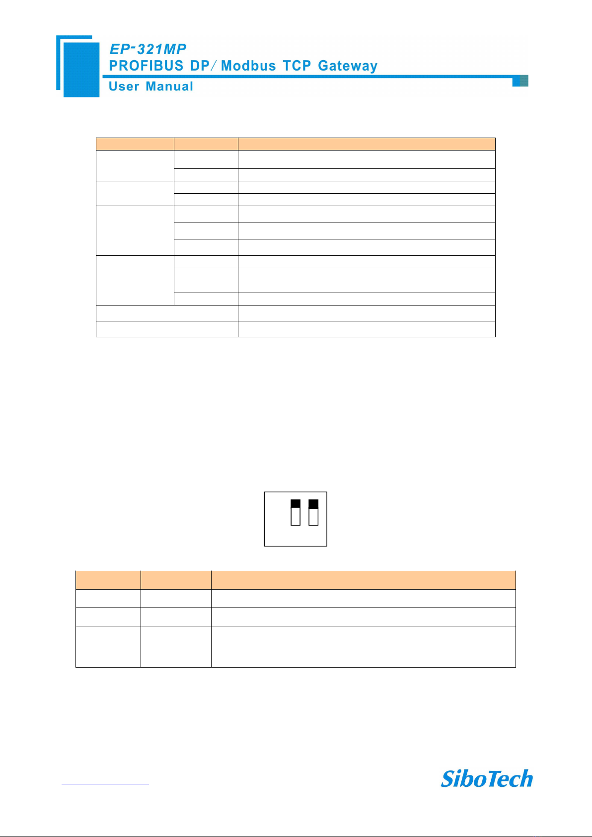
3.3 DIP Switch
3.3.1 Status Configuration Switch
The configuration switch is located on the button of the product. The function is listed below:
Off
On
1
Status(1)
Status(2)
Description
Off
Off
Run mode, allow reading and writing configuration data
Off
On
Run mode, reading and writing configuration data are not allowed
On
Off or On
Configuration mode, IP address is 192.168.0.10 (fixed), this mode can
read and write configuration data but cannot finish communication
between Modbus TCP and PROFIBUS DP
Notes:
Restart EP-321MP (power off and power on) after resetting the configuration to make the
configuration take effect!

www.sibotech.net/en
9
3.3.2 PROFIBUS DP Address Setting Switch
The 2-code rotary switch in the left-side is used for setting the PROFIBUS DP address of the device.
In this example, the PROFIBUS node address will be 42 ((4x10) + (2x1)).
3.4 Connectors
3.4.1 PROFIBUS DP Connector
DB9 pin
Function
3
PROFI_B, Data positive
5
GND (optional)
8
PROFI_A, Data negative
PROFI-B
PROFI-A
GND
PROFI-A
www.sibotech.net/en
10
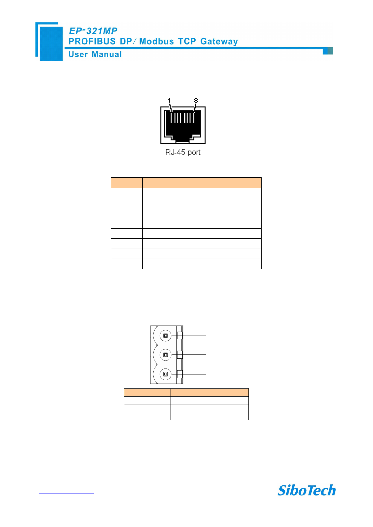
3.4.2 Ethernet Connector
pin
Signal Descriptions
S1
TXD+,Tranceive Data+,output
S2
TXD-,Tranceive Data-,output
S3
RXD+,Receive Data+,input
S4
Bi-directional Data+
S5
Bi-directional Data-
S6
RXD-,Receive Data-,input
S7
Bi-directional Data+
S8
Bi-directional Data-
3.4.3 Power Connector
GND
NC
24V+
1
2
3
Pin
Function
1
GND, Power ground
2
NC, not connected
3
24V+, 24VDC
www.sibotech.net/en
11
4 Modbus TCP master
4.1 Working Principle
The Ethernet port supports Modbus TCP master functions, as follows:
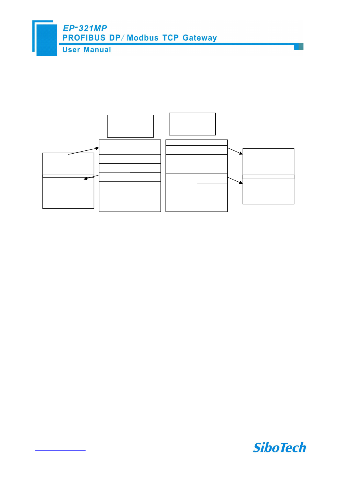
Data exchange of Modbus TCP and PROFIBUS DP of EP-321MP is set up through “mapping”. There are
two data buffer areas, one is PROFIBUS DP network input buffer and the other is PROFIBUS DP network output
buffer. When the gateway acts as Modbus TCP master, Modbus read commands will write the read data to the
network input buffer for PROFIBUS DP accessing. Modbus write register commands get data from network
output buffer and export to the Modbus TCP slave equipment through write command.
Modbus TCP can support up to 36 Modbus TCP slave nodes and 128 commands, each command reads a set
of consecutive Modbus registers.
Modbus
device 3
Modbus
device 4
Modbus
device 5
Modbus
device 6
Input Buffer
Output Buffer
www.sibotech.net/en
12
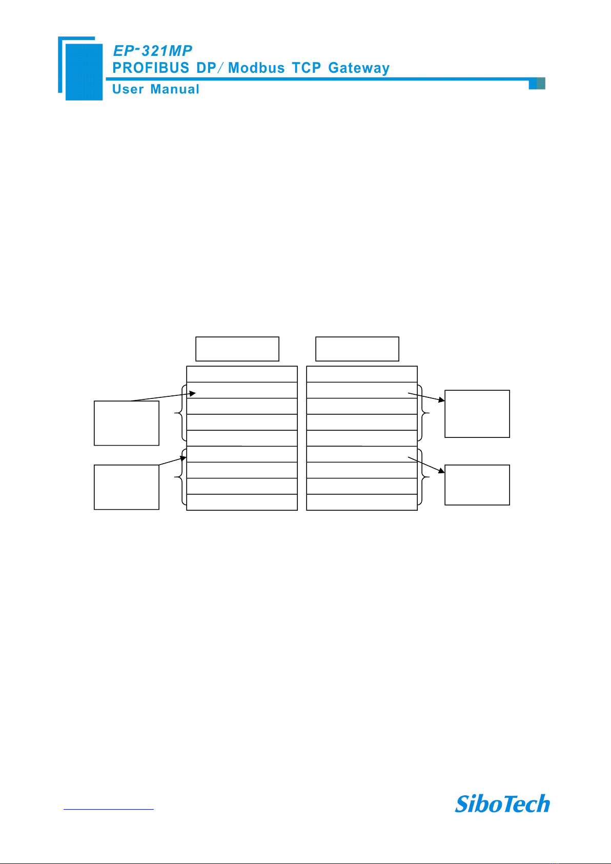
5 Modbus TCP Slave
5.1 Working Principle
Data exchange of Modbus TCP and PROFIBUS DP of EP-321MP is set up through “mapping”. There are
two data buffer areas, one is PROFIBUS DP network input buffer and the other is PROFIBUS DP network output
buffer. Network input and output buffer is all for PROFIBUS DP. When the gateway acts as Modbus TCP slave,
Modbus write register command will write the read data to the network input buffer for PROFIBUS DP accessing.
Modbus read command gets data from network output buffer and export to the Modbus TCP master equipment
through response message.
The gateway acts as Modbus TCP slave, support function: 03H, 04H, 06H and 10H. Users can select 03H
function code to read the data PROFIBUS DP master outputted or use 04H function code to read he data
PROFIBUS DP master outputted.
Network input buffer is Modbus TCP master output at the Modbus TCP side. It is mapped to the Modbus
holding register. Users can use No.3 command or No.4 command to read back. Users can select command No.
in the configuration software.
Network output buffer is Modbus TCP master input. It is mapped to Modbus input register. Users can use
No.4 or No.3 function code to read data. Users can select command No. in the configuration software.
5.2 Network Status Monitoring
When the Gateway is a Modbus TCP slave, the gateway has the function of monitoring the network status.
When the Monitoring is enabled, the first word of input buffer is used as counter which record the number of
TCP connections.
PROFIBUS
Input buffer
PROFIBUS
Output buffer
… …
0004H
0001H
0000H
0002H
0003H
0005H
0004H
0001H
0002H
0000H
0003H
0005H
… …
Modbus Write
command 06,10H
Modbus
Read command
03H or 04H
Modbus
Read command
03H or 04H
Modbus
Read command
03H or 04H
www.sibotech.net/en
13
6 Configuration Software EP-123
6.1 About EP-123
EP-123 is a Windows-based platform, used to configure EP - 321MP and other products.
Here is to introduce the use of EP-123.Double-click on the icon to enter the main interface:
6.2 User Interface
EP-123 user interface include: title bar, menu bar, toolbar, status bar, equipment plate, configuration plate and
comment plate.
Note: In this software, all gray parts cannot be modified.
www.sibotech.net/en
14
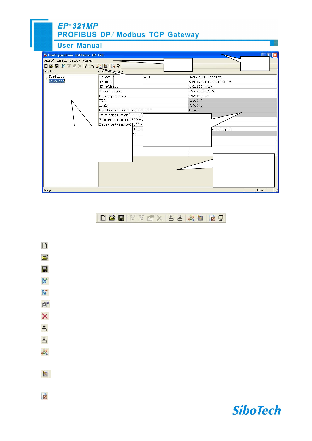
Toolbar:
Toolbar as shown below:
The function from left to right is: New, Open, Save, Add Nodes, Delete Nodes, Add Commands, Delete
Commands, Upload Config, Download Config, Conflict Detect, Auto Mapping, Export Xls and Monitor I/O data.
New: Create a new project
Open: Open a project
Save: Save the project
Add a node: Add a Modbus TCP slave
Delete a node: Delete a Modbus TCP slave
Add command: Add a Modbus command
Delete command: Delete a Modbus command
Upload: Upload the configuration form the gateway
Download: Download the configuration into the gateway
Conflict detection: To check whether there are some conflicts with configured commands in the gateway
memory data buffer
Auto mapping: Used to automatically calculate the mapped memory address without confliction by each
command
Export Excel: Export the configuration into Excel
Equipment plate:
Users can choose operation
object, includes Ethernet type,
adding node and command
Menu Bar
Title Bar
Configuration plate:
Input configuration
parameters, gray parts cannot
be modified
Comment plate:
Explain the function of the
configuration options
Toolbar

www.sibotech.net/en
16
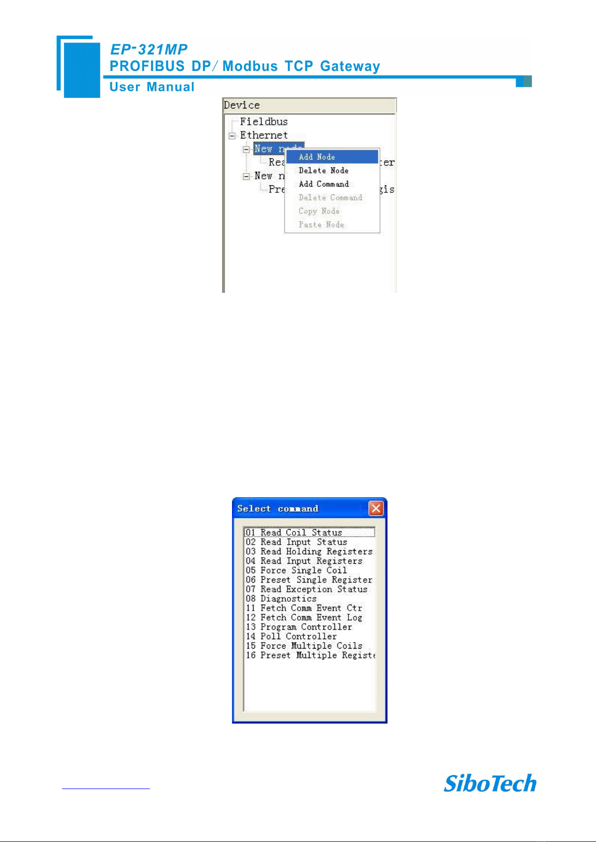
6.3.3 Equipment View Operation Types
1) Add node operation: Left click on Ethernet or existing nodes, and then perform the operation of adding a
new node. Then there is a new node named "New node" under Ethernet.
2) Delete node: Left click on the node to be deleted, and then perform the operation of deleting the node. The
node and all commands will be deleted.
3) Add commands: Left click on the node, and then perform the operation of adding command to add a
command for the node. It will pop up the command selecting dialog box for users to choose. Shown as below:
Select the command: Double click command item

www.sibotech.net/en
17
4) Delete commands: Left click on the command to be deleted, perform the operation of deleting the
command.
5) Edit node: Left click the node needs to be reset, and then set parameters of this node in configuration
interface.
6) Copy node: Left click the existing node, choose the node and execute the operation of copying nodes
(include all commands under the node)
7) Paste node: Left click and choose any existing node, execute operation of paste node. Then at the Ethernet
rear part you can see a new node (include all commands under the node); Node parameters of new node is default
setting, it needs to be reset.
6.4 The Operation of Configuration Interface
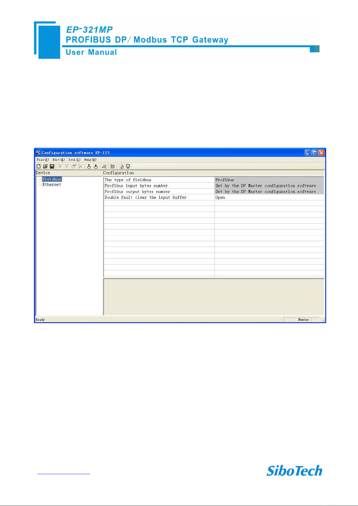
6.4.1 Fieldbus Configuration Interface
Click the fieldbus,the Fieldbus Configuration Area display configuration is as follows:
The configurable items include:
Bus Type: PROFIBUS DP
PROFIBUS DP input bytes: set by the PROFIBUS DP master configuration software
PROFIBUS DP output byte: set by the PROFIBUS DP master configuration software
Double fault clear: open and close optional.

www.sibotech.net/en
18
6.4.2 Ethernet Configuration Interface
Click Ethernet in configuration view interface; when choosing a different type of protocol, the configuration
view interface and configurable items are different.
The protocol type selection: Modbus TCP master
Modbus TCP master configuration view is shown as follows:
The configurable items include: assign IP mode, IP address, subnet mask, gateway address, DNS1, DNS2,
response timeout, delay between polls, output mode. As shown below:
Assign IP mode: Manual Assign, BOOTP and DHCP optional.
Response wait time: After the Modbus TCP master sent out commands, it waited for response from the slave.
Delay between polls: A Receive the right response after one Modbus command has been sent or sending next
Modbus command after response timeout.
Output mode: Continuous output, disable output and change-of-value output can be selected.
The protocol type selection: Modbus TCP Slave
Modbus TCP slave configuration view is as follows:

www.sibotech.net/en
19
Assign IP Mode: Manual Assign, BOOTP and DHCP optional, default value is manual assign;
Check unit ID: open and close optional.
Unit ID (1~255): valid when “Check unit ID” is opened, 1~255 optional.
Scan rate: the ratio of slow scan cycle and fast scan cycle.
Network status indication: mutual surveillance of both ends, PROFIBUS DP monitors the network state of
Modbus TCP, Modbus TCP monitor PROFIBUS DP network state and no indicating optional.
Modbus TCP master read data function code: "04H read the data DP sent to the Ethernet, 03H read back the
written data","03H read the data DP sent to the Ethernet, 04 read back the written data" is optional. Among them:
"04H read the data DP sent to the Ethernet, 03H read back the written data" means that Modbus TCP master is
using the 04H function code to read the output data from the PROFIBUS DP master to the Ethernet side, the use
of 03H read back the written data of the PROFIBUS DP master; "03H read the data DP sent to the Ethernet, 04
read back the written data" means that Modbus TCP master is using the 03H function code to read the output data
from the PROFIBUS DP master to the Ethernet side, the use of 04H read back the written data of the PROFIBUS
DP master.
The first address of read-only register (data direction: DP to Ethernet): range 0 to 65535, default value of 0;
The first address of the read/write registers (data direction: Ethernet to DP),: range 0 to 65535, default value
of 0.
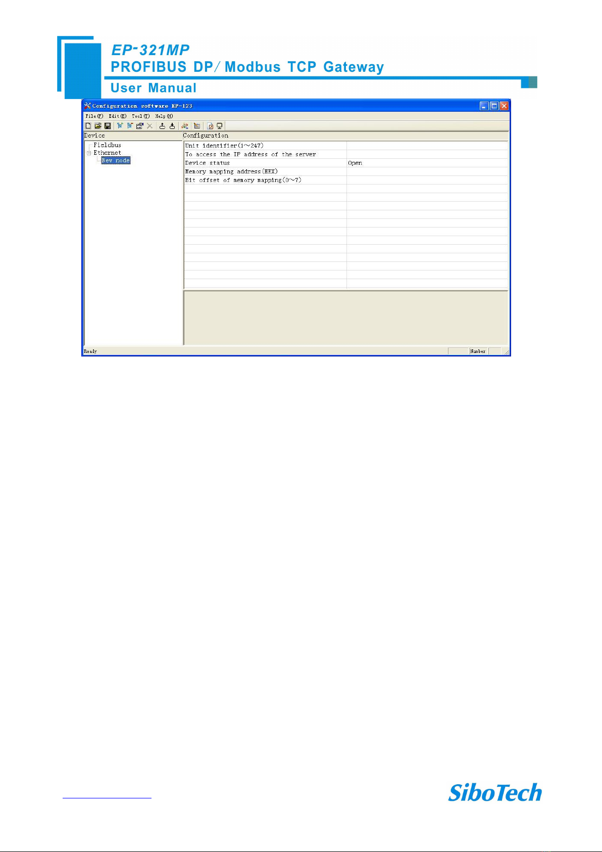
6.4.3 Node Configuration Interface
In the equipment view, click on the Ethernet, the protocol type is Modbus master, right-click on the
"Ethernet", adding new nodes, the node configuration view interface displays the following:
www.sibotech.net/en
20
Configurable parameters: Unit identifier to access the server's IP address, device status, memory-mapped
address, and memory-mapped offsets
The unit identifier: Modbus TCP slave address 1 to 247 optional.
To access the server IP address: IP address to access Modbus TCP slave.
Device status: open, close, optional. When it is opened, memory-mapped address and memory-mapped bits
offset is available.
Memory mapped address (HEX): Address range that equipment state is mapped in the module memory,
0x0000~0x00F3. Calculate by clicking “Auto mapping”.
Bit offset of memory mapping (0~7): Bit x where equipment state is in memory mapping byte, 0~7.
Table of contents
Other SiboTech Gateway manuals


