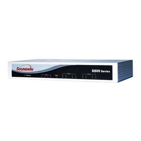
Soundwin TG400 Series User manual

TG400/TG800 Series
VOIP Voice Gateway
U
U
US
S
SE
E
ER
R
R
M
M
MA
A
AN
N
NU
U
UA
A
AL
L
L
Version: 2.0.1
Default
Login
Details
WAN IP Address: DHCP
LAN IP
Address:
http://222.222.222.1
User
Name: admin
Pa
ss
wo
r
d: admin

2
Preface .....................................................................................................................................5
0.1 About this manual ...........................................................................................................5
0.2 Copyright ........................................................................................................................5
0.3 Trademark.......................................................................................................................5
0.4 Safety Instructions...........................................................................................................5
0.5 Repair Warranty..............................................................................................................5
Introduction..............................................................................................................................6
1.1 Overview.........................................................................................................................6
1.2 Acronyms Table...............................................................................................................6
1.3 Introduction ....................................................................................................................7
1.4 Front panel LED description.............................................................................................7
1.5 Product Specifications .....................................................................................................9
1.6 Telephone Specifications.................................................................................................9
1.7 IP Specifications ..............................................................................................................9
1.8 Call function ....................................................................................................................9
1.9 setting and management.................................................................................................9
1.10 Basic Specifications......................................................................................................10
Installation and setting............................................................................................................11
2.1 packing contents ...........................................................................................................11
2.2 Hardware Installation....................................................................................................12
2.3 Quick Start ....................................................................................................................12
Network setting ......................................................................................................................14
3.1 Internet.........................................................................................................................14
3.1.1 Static IP ......................................................................................................................15
3.1.2 DHCP Mode................................................................................................................16
3.1.3 PPPoE Mode...............................................................................................................17
3.1.4 PPTP with WAN (Static, DHCP, PPPoE) ........................................................................18

3
3.1.5 L2TP with WAN (Static, DHCP, PPPoE).........................................................................19
3.2 LAN interface ................................................................................................................20
3.2.1 User list......................................................................................................................20
3.3 Dynamic DDNS ..............................................................................................................21
3.4 QOS setting ...................................................................................................................22
3.5 NAT Mode / Bridge mode..............................................................................................22
SIP Setting...............................................................................................................................23
4.1 SIP setting .....................................................................................................................23
4.1.1 Proxy server setting....................................................................................................23
4.1.2 SIP Advance Setting....................................................................................................25
4.1.3 Codec.........................................................................................................................26
4.2 Call Feature...................................................................................................................27
4.2.1 Call Forward Setting ...................................................................................................27
4.2.2 Do Not Disturb ...........................................................................................................28
4.3 Dialing Rule ...................................................................................................................28
4.3.1 Dialing Plan ................................................................................................................28
4.3.2 Hotline Setting............................................................................................................29
4.4 NAT Traversal................................................................................................................30
Advance setting ......................................................................................................................31
5.1 Phone setting ................................................................................................................31
5.1.1 Common ....................................................................................................................31
5.1.2 Volume Control ..........................................................................................................31
5.1.3 Loop Current control ..................................................................................................32
5.1.5 Flash Hook..................................................................................................................33
5.1.5 SLIC Setting ................................................................................................................34
5.1.6 Polarity Reversal.........................................................................................................34
5.1.7 Caller ID Setting..........................................................................................................35

4
5.2 Region Tone Setting ......................................................................................................36
5.3 DSCP Setting..................................................................................................................36
5.4 Voice Prompt ................................................................................................................36
Maintenance...........................................................................................................................38
6.1 System ..........................................................................................................................38
6.1.1 Account Setting ..........................................................................................................38
6.1.2 Time Setting ...............................................................................................................38
6.2 Tool...............................................................................................................................39
6.2.1 Backup / Restore ........................................................................................................39
6.2.2 Firmware Upgrade......................................................................................................40
6.2.3 Ping testing ................................................................................................................40
6.2.4 Restart .......................................................................................................................41
6.3 Langue ..........................................................................................................................41
Installation structure...............................................................................................................42

5
Preface
0.1 About this manual
This manual is intended to help users to the proper use of TG400/TG800 series VOIP voice
gateway.
The manual will be different based on the different firmware version, the latest content
(specifications) subject to the original notice, if any content in this document is supposed to
change without notice.
0.2 Copyright
All rights reserved for the 2009 Telephony Corporation. The information contained in this
publication is protected by copyright. Without written permission, no part of the copy,
transmitted, transcribed, or translated into any language, will be stored in a retrieval system,
ownership of copyright owners.
0.3 Trademark
Appear in this manual product and company names may be related to the company's
registered trademark that appears in this manual product and company names used only for
identification or explanation.
0.4 Safety Instructions
Use only the required power supply voltage. Power input: AC 100 - 240V, 50 - 60 Hz. To reduce
the risk of electric shock, do not disassemble this product. Opening or removing components
could be dangerous. Incorrect assembly may result in abnormal or damaged product, please
refer to the instruction manual before use.
Do not place any objects or liquid into the device, may cause electric shock, abnormal or
damaged products. Products will not produce any liquid. If the product is found around the
liquid leaks, identify and find the appropriate service personnel.
Use the unshielded twisted pair (UTP) Ethernet cable connection RJ - 45 port.
0.5 Repair Warranty
Users buy TG400/TG800 series VOIP voice gateway products from the dealer have one year
warranty. Be sure to obtain proof of purchase to the dealer and keep it. During the warranty
period, if the product has any abnormalities, failure resulting in the not function proper, we will
evaluate the repair fee or replacement of defective products or parts without charge. If the
product is modified, abuse, tampering, destruction by improper use, or under abnormal
operating conditions, such behavior is not apply the warranty policy. This warranty does not
include other ancillary products authorized software vendor or accessories.

6
1
Introduction
TG400/TG800 Series VoIP Gateway (VOIP Gateway) and Call Manager (Call Manage) include
low-to high-end Internet telephony overall solution. This article describes how to use the Voice
Gateway (VOIP Gateway) and Call Manager (Call Manage).
1.1 Overview
Internet Telephony Gateway (VOIP Gateway) is a communication device that can be
integrated analog phone, PSTN, or PBX trunk card/extension card.
TG400/TG800 series voip gateway can be connected with personal computers, such as IP
sharing / router, it may be a separate device, such as telecommunications and Internet
service providers (VPN).
Provide a direct analog port. For computer modulation decoders, fax machines, analog
phones and other devices, the analog port is necessary.
Support for standard Internet services such as IP sharing, NAT, Dynamic DNS (DDNS),
Quality of Service (QoS), port filtering, IP filtering.
1.2 Acronyms Table
Acronym:
Full Name:
Acronym:
Full Name:
API
Application Interface
ACI
Audio CODEC Interface
ADC
Analog to Digital Converter
CODEC
Coder / Decoder
DAC
Digital to Analog Converter
DC
Direct Current
DDNS
Dynamic Domain Name System
DHCP
Dynamic Host Configuration
Protocol
DMZ
Demilitarized Zone
DNS
Domain Name System
DTMF
Dual Tone Multi Frequency
FXO
Foreign Exchange Office
FXS
Foreign Exchange Station
GMT
Greenwich Mean Time
IP
Internet Protocol
IPSec
Internet Protocol Security
L2TP
The Layer 2 Tunnel Protocol
LAN
Local Area Network
WAN
Wide Area Network
MAC
Media Access Control
MII
Media Independent Interface
NAT
Network Address Translation
NTP
Network Time Protocol
PPTP
Point-to-Point Tunneling

7
Protocol
RTP
Real-Time Transport Protocol
RTCP
Real-Time Transport Control
Protocol (also known as RTP
control protocol)
SIP
Session Initiation Protocol
SLIC
Subscriber Line Interface Circuit
STUN
Simple Traversal of UDP through
NATs
URI
Uniform Resource Identifier
TCP
Transmission Control Protocol
UDP
User Gateway gram Protocol
UPnP
Universal Plug and Play
VoIP
Voice Over Internet Protocol
1.3 Introduction
combines VoIP and traditional analog phone
Support SIP VoIP protocol.
TG400 series: allow 4 SIP call
TG800 series: allow 8 SIP call
equipped with basic 4-port IP sharing function
Model
FXS Port
FXO port
WAN Port
LAN Port
RJ-11 port
SIP
TG400
4
1
4
4
TG402
2
2
1
4
4
TG404
4
1
4
4
TG800
8
1
4
8
TG804
4
4
1
4
8
TG808
8
1
4
8
1.4 Front panel LED description
TG400 Series:
LED STATUS indication
Power Green light on power on
Off power off
REG Green light on SIP account registered successfully

8
Green light flashing registering
Red light on SIP account registered failed
If any account registered failed, it
shows red light.
P1 / P2 Green light on VoIP call using
P3 / P4 Green light flashing VoIP / PSTN line rings
Orange light on PSTN call using
WAN Off Waiting for network connection
Green light on network connection established
Green light flashing Data traffic on cable network
LAN Off Ethernet not connected to PC
Green light on LAN is connected successfully
Green light flashing Data is transmitting
TG800 Series:
LED STATUS Indication
Power Green light on power on
Off power off
REG Green light on SIP account registered successfully
Green light flashing registering
Red light on SIP account registered failed
If any account registered failed it
shows red light.
P1 / P2 / P3 / P4 Green light on VoIP call using
P5 / P6 / P7 /P8 Green light flashing VoIP / PSTN line rings
WAN Off Waiting for network connection
Green light on network connection established
Green light flashing Data traffic on cable network
LAN Off Ethernet not connected to PC
Green light on LAN is connected successfully
Green light flashing Data is transmitting

9
Specifications
TG400/TG800 series VOIP Gateway provides many functions such as built-in server and
software, providing a convenient interface linking to your VoIP network.
1.5 Product Specifications
Support SIP protocols: SIP Registration and Digest Authentication Registration
NAT pass through: the function allowed TG400/TG800 series VOIP Gateway are able to
support any NAT / firewall, the default setting is the same as NAT / firewall virtual device
setting.
Telephone status display: This feature shows the status of each Port, such as phone on
hook / off hook, outgoing and incoming calls, talking time, caller ID.
1.6 Telephone Specifications
Codec: G.711 (A-law /μ-law), G.729 AB, G.723 (6.3 Kbps / 5.3Kbps), G.726 (16,24,32,40
Kbps), GSM-FR
FAX support: T.38, G.711 pass through
G.168 echo cancellation
Call Transfer: transfer when line busy / transfer without any condition / transfer when no
one pick up
DTMF Relay: In-band DTMFRelay /RFC2833
1.7 IP Specifications
SIP (RFC 3261) , SDP (RFC 2327), Symmetric RTP
STUN (RFC3489), ENUM (RFC 2916), RTP Payload for DTMF Digits (RFC2833), Outbound
Proxy Support
WAN: PPPoE client, DHCP client, Static IP Address, DDNS client
Support PPTP/L2TP VPN Client
Network Address Translation: Providing build-in NAT router function
QOS
1.8 Call function
volume adjustment:-32〜31(dB)
Dynamic Jitter Buffer
caller ID detection :DTMFCID / Bellcore CID/ ETSI CID
caller ID generation:DTMFCID / Bellcore CID/ ETSI CID
1.9 setting and management

10
Web-based Graphical User Interface
Remote management over the IP Network.
Backup and Restore Configuration file.
1.10 Basic Specifications
AC : TG400 series: AC100V-240V, DC12V/1.5A, 50/60 Hz,
TG800 series: AC100V-240V, DC12V/2.5A, 50/60 Hz,
Temperature:0°C~40°C (operation)
Humidity:90% non condensing
Emissions:meet FCC Part 15 Class B, CE Mark request

11
2
Installation and setting
2.1 packing contents
Please check the closed packing of products and accessories before installation. The following
are the default contents of the product. The contents of the actual product may be varied
according to different versions.
TG400/TG800 series VOIP Gateway packing contents
TG400 series TG800 seris
Adapter RG-45 cable User manual
TG400 series packing contents
TG400 series device
X 1
RJ-45 cable
X 1
AC adaptor (1.5 A)
X 1
CD-Rom (user manual)
X 1
TG800 series packing contents
TG800 series device
X 1
RJ-45 cable
X 1
AC adaptor (2.5 A)
X 1
CD-Rom (user manual)
X 1

12
2.2 Hardware Installation
TG400:
TG800:
item
Connect interface
Function
1
FXS
FXS port connected to phone or PBX outbound card.
2
FXO
FXO port connected to PBX inbound card or CO line
Back up for life line support, it’s used for PSTN call if
VOIP Call fails.
3
WAN
Connected to internet. The WAN port is able to connect
the gateway and modem (such as cable modem, ADSL
modem) to internet.
4
LAN
Connected to PC or switch /hub. Let your PC or Switch
/hub connected gateway to create LAN environment.
5
RESET bottom
Push the reset bottom till 3 sec. Gateway will be set to
default
6
AC power(DC in 12V)
Power input
2.3 Quick Start
How to set up TG400/TG800 series VOIP gateway?
1. Connect your PC or NB to LAN port of TG400/TG800 series voip gateway
2. Key in http://222.222.222.1 on web browser (IE / Firefox)
3. Enter user name and password
User name: guest password: guest
Admin user name: admin Admin password: admin
4. Enter wizard mode
1. Connection Setup
2. VOIP Setup

13
TG400/TG800 series voip gateway internet setting
1. Time zone setting
2. LAN IP, subnet mask IP setting (please keep default setting if not necessary to change the
IP))
3. WAN internet setting
WAN connection type, please choose your networking type
Static IP (fixed IP, IP information provided by ISP)
DHCP Client (distributing IP automatically)
PPPoE (account / password provided by ISP)
5. Click “end”and finish the internet setting, then, go to “VOIP Setup”to configure the SIP
account.
6. Connect TG400/TG800 series voip gateway to your internet environment
(Connect RJ45 cable to WAN port of TG400/TG800 series voip gateway).
7. The device will set up voip information automatically if devices setting finished
8. The TG400/TG800 series voip gateway LED light showed green light on: "REG" port after 2
sec, which means the device registered automatically and successfully
9. Start to call voip call
Notice: If REG is red light, it means the wrong account registration or not connected to internet.
If there is no sign on REG light, it means the account doesn’t open yet, please contact your
supplier.

14
3
Network setting
3.1 Internet
WAN (Wide Area Network) is a network connection connecting one or more LANs together
over some distance. For example, the means of connecting two office buildings separated by
several kilometers would be referred to as a WAN connection. The size of a WAN and the
number of distinct LANs connected to a WAN is not limited by any definition. Therefore, the
Internet may be called a WAN.
WAN Settings are settings that are used to connect to your ISP (Internet Service Provider). The
WAN settings are provided to you by your ISP and often times referred to as "public settings".
Please select the appropriate option for your specific ISP.
For most users, Internet access is the primary application. TG400/TG800 series voip gateway
supports the WAN interface for internet access and remote access. The following sections will
explain more details of WAN Port Internet access and broadband access setup. When you click
“WAN Setting”, the following setup page will be shown. Three methods are available for
Internet Access.
1. Static IP
2. DHCP
3. PPPoE

15
3.1.1 Static IP
If you are a user with static IP address, please enter the IP address, subnet mask, default
gateway and DNS servers, which are provided by your ISP (Internet Service Provider). Each IP
address must be entered in the field of IP in the appropriate forms, which are four IP octets
separated by points (XXXX). Router will not be accepted if IP address not like in this format. For
example: 168.95.1.2

16
□IP Address: Check with your ISP provider.
□Subnet Mask: Check with your ISP provider.
□Default Gateway: Check with your ISP provider.
□MTU size: MTU stands for Maximum Transmission Unit, the largest physical packet size,
measured in bytes that a network can transmit. Any messages larger than the MTU are divided
into smaller packets before being sent.
The key is to be deciding how big your bandwidth pipe is and select the best MTU for your
configuration. For example, you have a 33.6 modem, you use a MTU of 576, and if you have a
larger pipe you may want to try 1500.
□DNS server: enter DNS server (suggest default setting)
□Enable Keep Alive
3.1.2 DHCP Mode
Dynamic Host Configuration Protocol (DHCP), Dynamic IP (Get WAN IP Address automatically).
If you are connected to the Internet through a Cable modem line, then a dynamic IP will be
assigned.
Note: WAN port gets the IP Address, Subnet Mask and default gateway IP address
automatically, if DHCP client is successful.

17
□Name of service: it may be set by your own or blank
□MTU size: enter MTU (Maximum transmission unit) size (suggest set to default)
□Assign DNS Dynamically: get DNS IP address WAN interface automatically (suggest use it)
□First DNA server, Second DNS server: Manually enter the domain name server WAN interface
3.1.3 PPPoE Mode
Point-to-Point Protocol over Ethernet (PPPoE). Some ISPs provide DSL-based services and use
PPPoE to establish communication link with end-users. If you are connected to the Internet
through a DSL line, check with your ISP to see if they use PPPoE. If they do, you need to make
sure the following items, PPPoE User name: Enter username provided by your ISP. PPPoE
Password: Enter password provided by your ISP.

18
□USER name: the user name provided by your ISP
□user password: enter password provided by your ISP
□Name of service: you may set up the name of service or blank
□Type of connection:
Continuous: will keep trying to connect internet while disconnect
Connect on demand: will be set according to the idle time when connection
Manual: connect or disconnect by manual
□Idle time: when the connection type is: Connect on demand, can set up the interval time to
reconnect internet
□MTU size: enter MTU (max transmission unit) size (suggest set to default)
□Server 1, 2: Manually enter the domain name server WAN interface
3.1.4 PPTP with WAN (Static, DHCP, PPPoE)
Some ISPs provide DSL-based service and use PPTP with Static, DHCP or PPPoE to establish
communication link with end-users.

19
□PPTP Server IP Address: check with your VPN PPTP Server provider
□PPTP User Name: PPTP Dial-in account
□PPTP Password: PPTP Dial-in Password
□PPTP MTU Size
□Request MPPE Encryption
□Remote LAN setting: select SIP Call by LAN IP Address or not
3.1.5 L2TP with WAN (Static, DHCP, PPPoE)
Some ISPs provide DSL-based service and use L2TP with Static, DHCP or PPPoE to establish
communication link with end-users.
□L2TP Server IP Address: check with your VPN L2TP Server provider
□L2TP User Name: L2TP Dial-in account
□L2TP Password: L2TP Dial-in Password
□L2TP MTU Size
□Request MPPE Encryption
□Remote LAN setting: select SIP Call by LAN IP Address or not

20
3.2 LAN interface
The IP settings of the LAN (Local Area Network) interface for the device. These settings may be
referred to as "private settings". You may change the LAN IP address if needed. The LAN IP
address is private to your internal network and cannot be seen on the Internet. The default IP
address is 222.222.222.1 with a subnet mask of 255.255.255.0.
LAN is a network of computers or other devices that are in relatively close range of each other.
For example, devices in a house or office building would be considered part of a local area
network
□LAN IP Address: Assign the IP address of LAN server, default is 222.222.222.1
□Subnet Mask: Select a subnet mask from the pull-down menu, default is 255.255.255.0.
□DHCP Server Setting: DHCP stands for Dynamic Host Control Protocol. The DHCP server gives
out IP addresses when a device is starting up and request an IP address to be logged on to the
network. The device must be set as a DHCP client to "Obtain the IP address automatically". By
default, the DHCP Server is enabled in the unit. The DHCP address pool contains the range of
the IP address that will automatically be assigned to the clients on the network.
When you enable the DHCP server,
□DHCP Client Range: Enter the starting IP address for the DHCP server’s IP assignment and the
ending IP address for the DHCP server’s IP assignment.
3.2.1 User list
The client computer is connected to the unit will display their information table in the DHCP
client list. The table displays the IP address, MAC address, and the lease time, DHCP lease
statistics for each time the client computer. Click Refresh to update the screen display
This manual suits for next models
1
Table of contents
Other Soundwin Gateway manuals