esera ECO 305 User manual

Art. No. 12020-230
All rights reserved. Reprinting, including excerpts, not permitted without the express consent of ESERA GmbH.
Subject to technical changes. ESERA GmbH 2023
www.esera.de 12020-230_Manual Page 1 from 25
OPERATING INSTRUCTIONS
ECO 305
PROFESSIONAL EBUS GATEWAY
Gateway of the latest generation for the eBus system
HIGHLIGHTS
eBus Gateway
optimized for ebusd** software
⎯
eBus interface to the
read and write for your
eBus heating system
⎯
Manufacturer-independent
⎯
Plug and Play System
⎯
Automatic eBus level adjustment
⎯
Web server and access point
for configuration, debug and firmware updates
⎯
Low maintenance industrial device, because
without Linux. Native programmed without
unknown libraries
⎯
LAN interface
for data, configuration, debug
and firmware updates
⎯
Rugged industrial design
⎯
Extensive protection circuits and good device
protection
⎯
Easy mounting on
Top-hat rail, 4TE (77mm)
⎯
Power supply 110-240VAC
This manual has been machine translated. The original manual and reference is the German manual.

All rights reserved. Reprinting, including excerpts, not permitted without the express consent of ESERA GmbH.
Subject to technical changes. ESERA GmbH 2023
www.esera.de 12020-230_Manual Page 2 from 25
TABLE OF CONTENT
1ADDITIONAL DOCUMENTS AND SOFTWARE..................................................................................3
2PRODUCT DESCRIPTION ...................................................................................................................4
3HIGHLIGHTS.........................................................................................................................................5
4ECO 305 EBUS GATEWAY..................................................................................................................6
5TECHNICAL DATA...............................................................................................................................7
6ENVIRONMENTAL CONDITIONS........................................................................................................8
7CONFORMITY.......................................................................................................................................8
8DISPLAY LED .......................................................................................................................................8
9SOFTWARE, EVALUATION EBUS DATA...........................................................................................9
10 FUNCTION TERMINALS ....................................................................................................................10
11 CONNECTION PLAN..........................................................................................................................10
12 ACTIVATE ACCESS POINT...............................................................................................................11
13 SELECT ACCESS POINT...................................................................................................................12
14 CALL WEB SERVER VIA WIFI ..........................................................................................................12
15 CALL WEBSERVER VIA LAN............................................................................................................13
16 WEBSERVER, LOG IN .......................................................................................................................13
17 MAIN PAGE.........................................................................................................................................14
18 ETHERNET INTERFACE SETTINGS.................................................................................................15
19 ASCII PROTOCOL SETTINGS...........................................................................................................16
20 DISABLE AP MODE ...........................................................................................................................17
21 WEBSERVER, CHANGE PASSWORD..............................................................................................18
22 WEBSERVER, FACTORY RESET .....................................................................................................18
23 WEBSERVER, EBUS FIRMWARE UPDATE.....................................................................................19
24 WEBSERVER, INTERFACE FIRMWARE UPDATE ..........................................................................20
25 DATA INTERFACE, ASCII PROTOCOL............................................................................................21
26 ESERA ASCII TEXT PROTOCOL ......................................................................................................21
27 EBUS NETWORK WIRING.................................................................................................................22
28 FIRMWARE UPDATE .........................................................................................................................22
29 RESET BUTTON.................................................................................................................................23
30 OPERATING CONDITIONS................................................................................................................23
31 INTENDED USE ..................................................................................................................................23
32 ELECTRICAL INSTALLATION...........................................................................................................24
33 ASSEMBLY.........................................................................................................................................24
34 MOUNTING LOCATION......................................................................................................................24
35 DISPOSAL...........................................................................................................................................24
36 SAFETY INSTRUCTIONS...................................................................................................................24
37 WARRANTY........................................................................................................................................25
38 WARNING ...........................................................................................................................................25
39 CONTACT ...........................................................................................................................................25
Art. No. 12020-230
All rights reserved. Reprinting, including excerpts, not permitted without the express consent of ESERA GmbH.
Subject to technical changes. ESERA GmbH 2023
www.esera.de 12020-230_Manual Page 3 from 25
1 ADDITIONAL DOCUMENTS AND SOFTWARE
In addition to the ECO 305 eBus Gateway operating manual, we also offer cross-product documents that are
valid for several devices.
You can find these documents and additional software on our website (https://esera.de) by following the links
below.
Please make sure that you read all the documents thoroughly and follow the information and instructions
contained. If you have difficulties finding the documents or software you need, do not hesitate to contact our
customer support (support@esera.de). We will be happy to help you with any questions or problems.
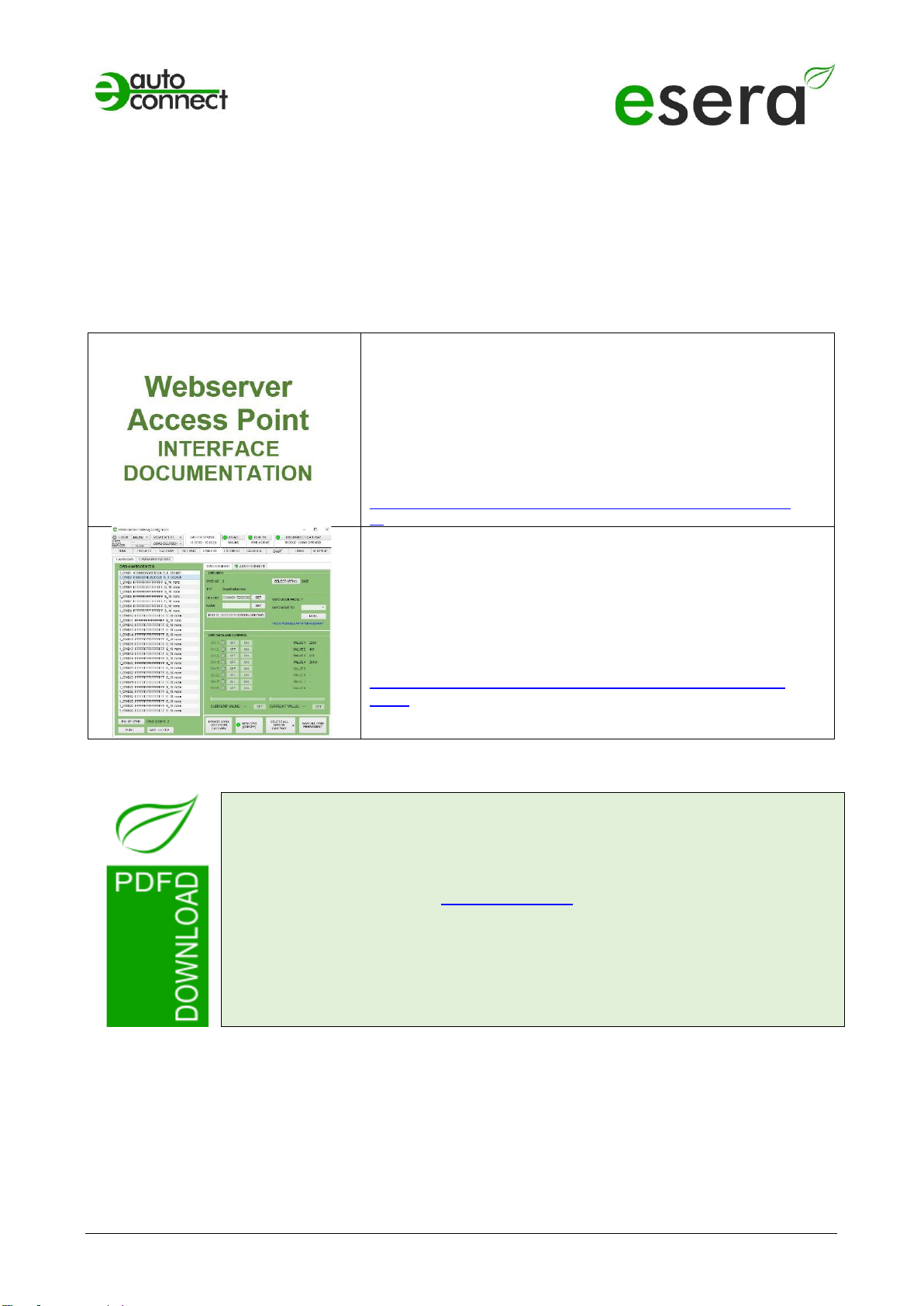
INTERFACE MANUAL
MODBUS, MQTT, LoRaWAN, NB-IoT
Manual for configuring the interface via web server and
access point
The manual can be found in the ESERA download area
at:
https://download.esera.de/download/technical/schnittstellen_handbu
ch
CONFIG TOOL 3 SOFTWARE
Comprehensive software for all EC and ECO gateways
with 1-Wire I/O section
You can find the software in the ESERA download area
at:
https://download.esera.de/download/technical/config%20tool
%203
Note
Before you start assembling the device and put the product into operation, read these
operating instructions through to the end at your leisure, especially the section on
safety instructions.
If you have problems downloading the advanced documents or software, please
We are very concerned to act in an environmentally friendly and resource-saving way
for you. That is why we use paper and cardboard instead of plastics wherever possible.
We would also like to make a contribution to the environment with these paperless
instructions.
Please think of the environment before printing these instructions.

All rights reserved. Reprinting, including excerpts, not permitted without the express consent of ESERA GmbH.
Subject to technical changes. ESERA GmbH 2023
www.esera.de 12020-230_Manual Page 4 from 25
2 PRODUCT DESCRIPTION
The ECO 305 eBus Gateway is a powerful interface of the latest generation that acts as a link between your
heating system and the ebusd* software. It allows you to access your heating system, independent of the
manufacturer, read and write and perform optimizations.
The eBus Gateway has been optimized especially for the communication with the software "ebusd "* and
supports the extended command set (Enhanced Mode) of ebusd*.
In addition to the eBus functions, the eBus gateway has an access point and a web server to enable easy
operation and configuration. You can communicate via the LAN interface using the ASCII text protocol with
up to 2 data connections.
The ECO 305 is a new eBus coupler with a standard eBus data interface and "Enhanced Mode" extension
for the ebusd software. The gateway does not perform any data analysis or evaluation itself.
The fully automatic level adjustment takes place in a few seconds on your eBus, so that a cumbersome
manual adjustment is no longer necessary.
You can conveniently change device settings, perform software updates and view device data via the web
server. The web server can be accessed via the LAN and via the access point (activated at the push of a
button).
The ECO 305 eBus Gateway is a low maintenance industrial device because it does not use Linux. It has
been programmed natively and no unknown libraries are used.
Extensive software support is available via ebusd** on the web. Additionally, we provide the free eConfig tool
for debug purposes.
Please note that the ECO 305 is not supported by the Vaillant vrDIALOG software.

Art. No. 12020-230
All rights reserved. Reprinting, including excerpts, not permitted without the express consent of ESERA GmbH.
Subject to technical changes. ESERA GmbH 2023
www.esera.de 12020-230_Manual Page 5 from 25
3 HIGHLIGHTS
Optimized for the ebusd** software
The gateway is specially optimized for use with the ebusd software.
eBus interface for reading and writing
You can access your eBus heating system and transfer both read and write data.
Manufacturer-independent
The gateway is compatible with various heating systems from different manufacturers. The heating systems
only need to have an eBus interface.
Plug and Play System
It's easy to install and set up, with no complicated setup processes.
Automatic eBus level adjustment
The level adjustment on the eBus takes place automatically and in a few seconds.
Web server and access point
The gateway has an integrated web server and access point for configuration, troubleshooting and firmware
updates.
Low maintenance industrial device
The gateway has been natively programmed without the use of Linux or unknown libraries to ensure reliable
and low-maintenance performance.
LAN interface
Data transfer, configuration, troubleshooting and firmware updates can be performed via the LAN interface.
Rugged industrial design
The gateway is designed in a rugged industrial version to meet the requirements in various environments.
Extensive protection circuits and good device protection
The gateway provides comprehensive protection circuits and reliable device security.
Simple assembly
The gateway can be easily mounted on a top-hat rail with 4TE (77 mm).
Power supply
The gateway supports a power supply in the range of 110-240VAC.
These functions make the ECO 305 eBus Gateway a powerful and versatile tool for controlling and
monitoring your heating system.
**ebusd is not software by ESERA GmbH. We do not assume any liability, promise of function or support for
this software.

All rights reserved. Reprinting, including excerpts, not permitted without the express consent of ESERA GmbH.
Subject to technical changes. ESERA GmbH 2023
www.esera.de 12020-230_Manual Page 6 from 25
4 ECO 305 eBus Gateway
The ECO 305 eBus Gateway offers several advantages that result in potential savings of
up to 25%* in heating costs and an increase in living comfort.
Here are some ways the gateway can help:
•Optimization of heating control
By accessing your heating system and being able to read and write to it, you can control and adjust
heating parameters more precisely. This allows you to operate your heating more efficiently and
reduce unnecessary energy consumption.
•Improved control of the room temperature
The ECO 305 gateway in combination with the ebusd software allows you to control and adjust the
room temperature more precisely. You can set up individual schedules and temperature profiles to
improve home comfort and save energy at the same time.
•Remote access and control
Thanks to the gateway's web server and access point function, you can conveniently access and
control your heating system from anywhere. This gives you flexible and easy remote monitoring and
control to optimize home comfort while minimizing energy consumption.
It is important to note that actual heating cost reduction and improvement in home comfort depend on
various factors, such as the efficiency of your heating system, building insulation and your individual usage
patterns. However, the ECO 305 eBus Gateway, together with the ebusd** software, offers you the
possibility to better control and optimize these aspects for potential savings and improved comfort.
*The stated heating cost reduction of up to 25% is for illustrative purposes only and may vary depending on
individual circumstances. It is not a guaranteed savings.
**ebusd is not software by ESERA GmbH. We do not assume any liability, promise of function or support for
this software.
DATA INTERFACE
The ECO gateway is equipped with an Ethernet interface that allows a speed of 10/100Mbit. It supports
different data protocols like TCP/IP or UDP. Up to 2 data connections can be used in parallel, which
enables efficient communication and data transfer. The Ethernet interface provides a reliable and fast
connection for data exchange between the gateway and other devices or systems.
ASCII TEXT PROTOCOL
The ECO 305 gateway ensures a direct and unaltered transmission of the data transmitted via the
eBus. It outputs the data in its native form via the data interface without evaluating or analyzing it. The
gateway forwards the data without any additional processing or interpretation. This ensures that the
received data is transmitted to the user unchanged and true to the original.
SELF-SUFFICIENT MANAGEMENT
The eBus gateway ECO 305 enables the independent reading of communication data of the eBus and
also offers the possibility to transfer commands to the eBus. This allows various actions to be carried
out, such as triggering a heating system or transmitting parameters to the central heating system. With
the help of the gateway, data can be written to and read from the eBus heating bus to control the
heating center or peripheral components such as pumps, mixers or a living room control unit. However,
it is important to note that the correctness of the command data is always the responsibility of the user.
The gateway itself does not perform any write or read actions independently.
DESIGNED FOR ALL eBus HEATING SYSTEMS
The eBus is a cross-company bus system used in heating construction. The ECO 305 eBus gateway
enables the connection with all heating systems which have this heating data bus. Please check
whether your heating system is also supported by the ebusd evaluation system. For more information,
please visit the ebusd website at www.ebusd.de.

Art. No. 12020-230
All rights reserved. Reprinting, including excerpts, not permitted without the express consent of ESERA GmbH.
Subject to technical changes. ESERA GmbH 2023
www.esera.de 12020-230_Manual Page 7 from 25
VOLTAGE SUPPLY
For the power supply, the ECO 305 is equipped with an integrated power supply unit that supports a wide-
range voltage input of 100VAC - 240VAC. This makes it ideally suited for stationary operation in a control
cabinet or control box. This voltage input option allows flexible installation of the gateway in different
environments and ensures a reliable power supply for the operation of the device.
5 TECHNICAL DATA
SPECIAL FEATURE
•eBus gateway/data interface is adapted to the ebusd** software
•Access to eBus heating bus reading and writing
•Manufacturer-independent
•For all heating systems with eBus interface, gas, oil, solar and heat
pumps
•Web server for configuration of data connections
•Internal access point available via pushbutton for 30 minutes
•High performance Ethernet interface
•WLAN antenna internal
DATA INTERFACE
•Ethernet, 10/100Mbit, autonegotiation, DHCP or fixed IP address
NUMBER OF DATA
CONNECTIONS
max. 2 parallel TCP/IP socket data connections
1 x binary 2400 baud, 8 data bits, no start bit, 1 stop bit
•1 x binary with enhanced ProProtocol for ebsud* with
115,2kBaud, 8 data bits, no start bit, 1 stop bit
PROTOCOL
ESERA ASCII text for eConfig tool,
19200 baud, 8 data bits, no start bit, 1 stop bit
OPERATING MODES
Standard ebus with 2400 baud and enhanced ProProtocol with
115.2kBaud
TCP Socket, TCP Client, UDP
EBUS INTERFACE
•Standard eBus interface
•Reverse polarity and overvoltage protection
•Automatic level adjustment to correct operating point
Input voltage high: 15-24 V, low: 9-12 V
POWER SUPPLY
110 - 240VAC
STROKE UP
max. 5 Watt at 230VAC, typical 2W at 230VAC
CONNECTION
Screw terminals for stranded wire and cable up to 2.5qmm cross-section
PROTECTIVE CIRCUITS
ESD, overvoltage and reverse polarity protection for the eBus
interface
CONNECTION
Screw terminals for stranded wire and cable up to 2.5qmm cross-
section
ISOLATION
Galvanic isolation between Ethernet and eBus interface

All rights reserved. Reprinting, including excerpts, not permitted without the express consent of ESERA GmbH.
Subject to technical changes. ESERA GmbH 2023
www.esera.de 12020-230_Manual Page 8 from 25
6 ENVIRONMENTAL CONDITIONS
Operating temperature
-5°C to +40°C, standard temperature range
Storage temperature
-10°C to +60°C
Relative humidity
10% to 92% (non-condensing)
Room classification
Operate only in dry rooms
Protection class
IP20
Protection class
II
Dimensions
2TE, 77 x 90 x 70mm (WxHxD)
7 CONFORMITY
EN 50090-2-2
EN 61000-4-2, ESD
EN 61000-4-3, HF
EN 61000-4-4, Burst
EN 61000-4-5, Surge
EN 61000-6-1, Noise immunity
EN 61000-6-3, Interference radiation
RoHS
8 DISPLAY LED
The module has different display LEDs. The function of the displays is as follows
ADVERTISEME
NT
DESCRIPTION
FUNCTION
LED Green
PWR
Display for supply voltage
LED Green
DATA
•After switching on the device, the LED flashes 3x
•Flashes during eBus activity
•Flashes when sending data via the data interface
LED Green
LAN
LAN - network status LED
Lights up when LAN network connection
is established
Flashes when the interface is not activated
LED Green
WLAN
WLAN - Network Status LED
Lights up when WLAN network connection is established
Flashes when the WLAN access point is activated and a direct
connection is possible

Art. No. 12020-230
All rights reserved. Reprinting, including excerpts, not permitted without the express consent of ESERA GmbH.
Subject to technical changes. ESERA GmbH 2023
www.esera.de 12020-230_Manual Page 9 from 25
9 SOFTWARE, EVALUATION EBUS DATA
The scope of delivery of the ECO 305 does not include any evaluation software. The ECO 305 gateway is
optimized for the ebusd software.
For the evaluation of the eBus data there are different projects on the Internet. We would like to
recommend the following projects.
The ebusd website also provides information on how to configure ebusd.
•ebusd website*: https://ebusd.de/
•Documentation on ebusd: https://github.com/john30/ebusd/wiki
*ebusd is not software by ESERA GmbH. We do not assume any liability, promise of function or support for
this software.
Documentation on eBus in general:
•eBus Wiki Page of the eBus Friends
Webside: (https://www.dokuwiki.org/start?id=de:dokuwiki
Notice:
•Vaillant vrDIALOG Software
The ECO 305 gateway is NOT supported by the Vaillant vrDIALOG software.
All rights reserved. Reprinting, including excerpts, not permitted without the express consent of ESERA GmbH.
Subject to technical changes. ESERA GmbH 2023
www.esera.de 12020-230_Manual Page 10 from 25
10 FUNCTION TERMINALS
The following is an overview of the terminals and their functions
KLEMME
DESCRIPTION
FUNCTION
3
Mains voltage
neutral conductor
Power supply of the eBus gateway,
Neutral - ladder, N
4
Mains voltage
phase
Power supply of the eBus gateway,
Phase - conductor, L
5
Functional earthing
FE
Connection for functional grounding
22
eBus connection "A
Connection of the eBus heating bus, terminal A
23
eBus connection "B
Connection of the eBus heating bus, terminal B
17
Reset button
Reset button for eBus section, not interface
All other terminals
that are not used
Not used
No function, not used
Do not insert any objects, tools or lines
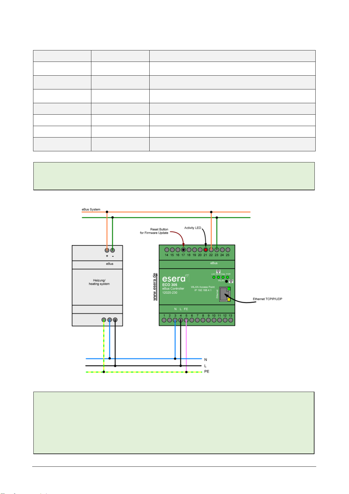
11 CONNECTION PLAN
NOTE
The module may only be operated at the voltages and under the ambient conditions specified for it. The
operating position of the device is arbitrary.
The modules may only be commissioned by a qualified electrician.
Carry out all connection work in a de-energized state.
For further information on the operating conditions, see the following instructions under "Operating
conditions".
NOTE
The FE connection of the ECO 305 must be connected to ground potential (PE). This establishes a
functional ground for reliable operation.
Art. No. 12020-230
All rights reserved. Reprinting, including excerpts, not permitted without the express consent of ESERA GmbH.
Subject to technical changes. ESERA GmbH 2023
www.esera.de 12020-230_Manual Page 11 from 25
12 ACTIVATE ACCESS POINT
The ECO Gateway with Maxi interface has a switchable WiFi (WLAN) access point.
This means that you can access the device via a mobile device such as a smartphone, tablet or laptop. This
is possible directly - without additional devices via WiFi (WLAN), access point (e.g. Fritzbox).
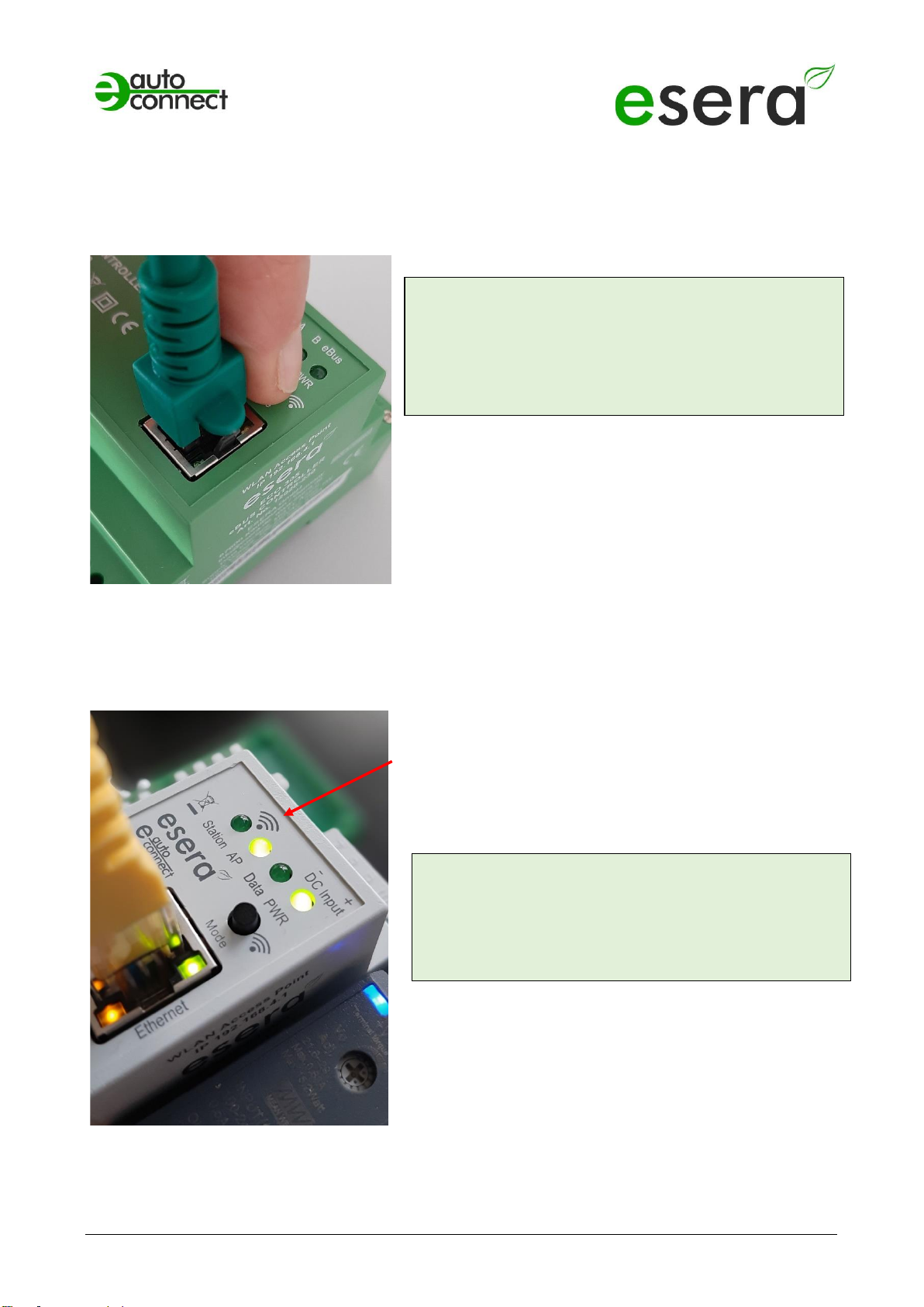
What is an access point?
With an access point (wireless LAN AP mode), mobile end devices such as laptops, tablets, smartphones,
etc. can be connected directly to the ECO Gateway. No additional wireless LAN access point is required.
When the access point is activated, we talk about the AP
mode of the WLAN interface of the ECO Gateway.
(See figure, LED "AP" is on, LED "Station" is off)
If you no longer need the access point, switch it off by
pressing the button again for atleast 5 seconds.
NOTE
You activate the access point by pressing (for 5 seconds)
the button on the top.
The access point is active for approx. 30 minutes. After
that, it deactivates automatically for security reasons.
You can switch off the access point by pressing it again
for at least 5 seconds.
NOTE
The web server is continuously available via the
Ethernet interface. You can reach it via the
IP address of the device.
The IP address of the ECO Gateway can be found on
the "Ethernet Interface Settings" web page
Access Point is activated
Push button to activate the Access Point

All rights reserved. Reprinting, including excerpts, not permitted without the express consent of ESERA GmbH.
Subject to technical changes. ESERA GmbH 2023
www.esera.de 12020-230_Manual Page 12 from 25
13 SELECT ACCESS POINT
The ECO gateway registers itself as a WLAN access point with the identifier "ESERA". In the delivery state,
the Ethernet interface is set to "DHCP".
The access point is open, without an access password.
14 CALL WEB SERVER VIA WIFI
If you have connected to the WLAN network "ESERA", the web browser starts directly on many
smartphones.
If this is not the case, switch to your web browser (e.g. Firefox, Chrome, etc.) and enter
enter the IP address of the ECO Gateway. Now the web server of the ECO Gateway should be visible,
comparable to the following picture.
The configuration of the device is currently only possible via
the web server of the ECO Gateway.
NOTE
The IP address of the ECO Gateway via Access
Point is: 192.168.4.1
The IP address of the access point is printed on the
right side of the gateway housing.
Important:
Enter the IP address without "https://".
Select "ESERA" Access Point
NOTE
The ECO WLAN access point can be found as a
WLAN network at the identifier "ESERA".
Art. No. 12020-230
All rights reserved. Reprinting, including excerpts, not permitted without the express consent of ESERA GmbH.
Subject to technical changes. ESERA GmbH 2023
www.esera.de 12020-230_Manual Page 13 from 25
15 CALL WEBSERVER VIA LAN
You can also connect the web server of the ECO Gateway at any time via LAN interface using the set
Reach IP address.
The IP address of the ECO Gateway is shown on the device display (if the device has a display). If the
device does not have a display, you can
also read out the current IP address (not the
IP address of the access point) via your router/DHCP server.
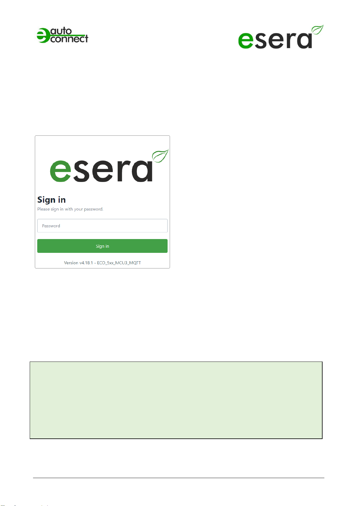
16 WEBSERVER, LOG IN
Password, Log In
To be able to log into the web server of the ECO
Gateway, use for the first login the
Startup/default password: eserapwd
For security reasons, the password is not displayed in
plain text, but with dots.
After entering the password, click on the "Login"
button to open the main menu (hereinafter referred to
as the main menu).
Please change the password after the first login,
otherwise unauthorized persons can also
make settings on the
ECO Gateway.
Please enter a new and secure password via the
main menu/"Change Password".
Advice on how to assign secure passwords can be
found on the Internet.
Software version Ethernet interface/Log Out
Display of the software version of the Ethernet
interface installed on the device. The version of the 1-
Wire firmware can be seen via the Config Tool 3.
Log Out
Click on the "Log Out" button to exit the web
interface.
NOTE
The startup/default password for login is: eserapwd
IMPORTANT
Please change the password after the first login.
For more details about functions of the web server, please refer to the document
"Interface Manual" that you can find via our website www.esera.de, download area/technical-
downloads.
All rights reserved. Reprinting, including excerpts, not permitted without the express consent of ESERA GmbH.
Subject to technical changes. ESERA GmbH 2023
www.esera.de 12020-230_Manual Page 14 from 25
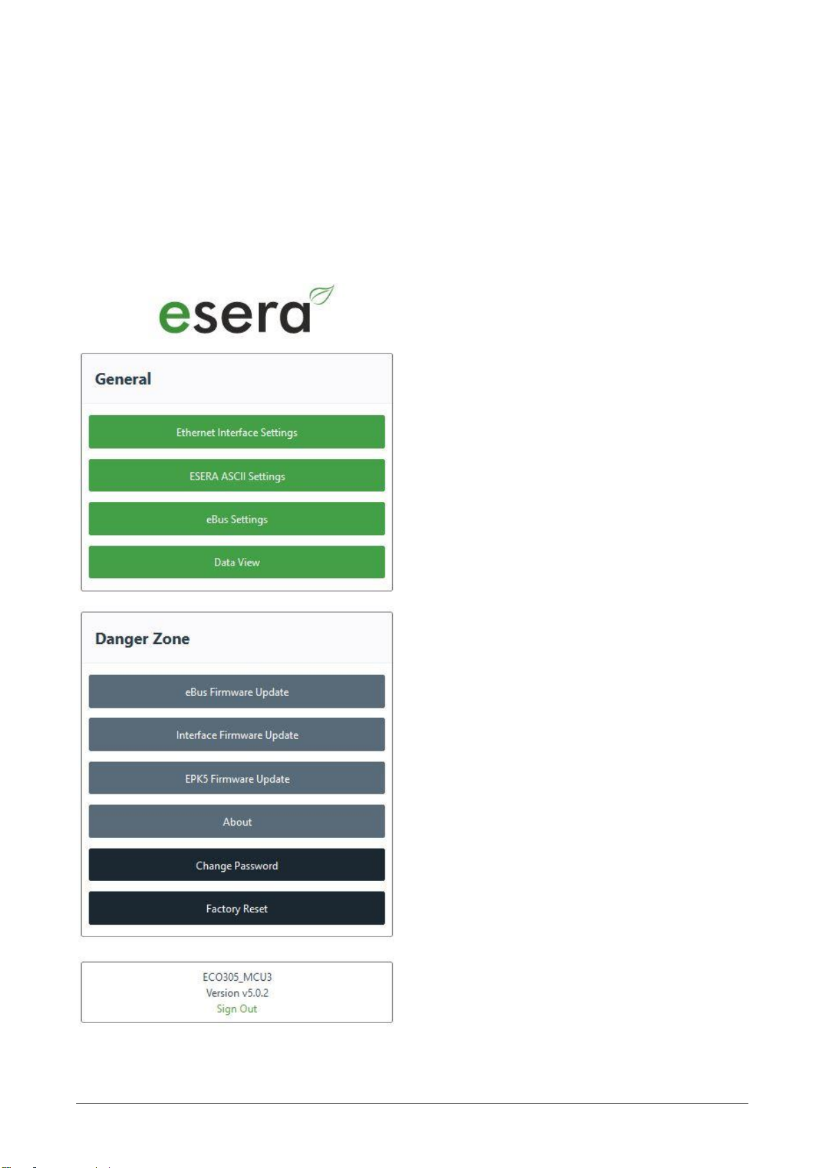
17 Main page
The ECO gateways are delivered with different equipment regarding interfaces and protocols.
The main page is divided into two sections:
General
Here you will find all menus for configuring the interfaces and viewing the gateway
and sensor data. The various buttons (selection keys) take you to the corresponding submenus, which are
described below.
Danger Zone
Here you get to submenus where you should take great care, because the possible changes are usually not
undoable.
Ethernet Interface Setting
Use this button to enter the menu for setting the IP
address, Sub Net and Gateway number.
ESERA ASCII Settings
From here you come to the submenu for setting the
data port. Pressing the button takes you to the menu
for configuring socket interfaces 2 - 5.
Data View
Here you can view the gateway data and the sensors
connected via the 1-Wire bus system. Here you will
also find the Auto-E-Connect information.
Firmware update, eBus, I/O section
Using this button you can perform an update of the
eBus Section perform.
Firmware Update Interface Section
This button allows you to perform a firmware update
of the interface and the web server.
Change Password
To change the password for the web server, click the
"Change Password" button.
Factory Reset
You may reset the Ethernet interface to the delivery
state. For this press the button "Factory Reset
Software version Ethernet interface/Log Out
Display of the software version of the Ethernet
interface installed on the device. The version of the 1-
Wire firmware can be seen via the Config Tool 3.
Sign Out
Click the "Sign Out" button to exit the web server.
Art. No. 12020-230
All rights reserved. Reprinting, including excerpts, not permitted without the express consent of ESERA GmbH.
Subject to technical changes. ESERA GmbH 2023
www.esera.de 12020-230_Manual Page 15 from 25
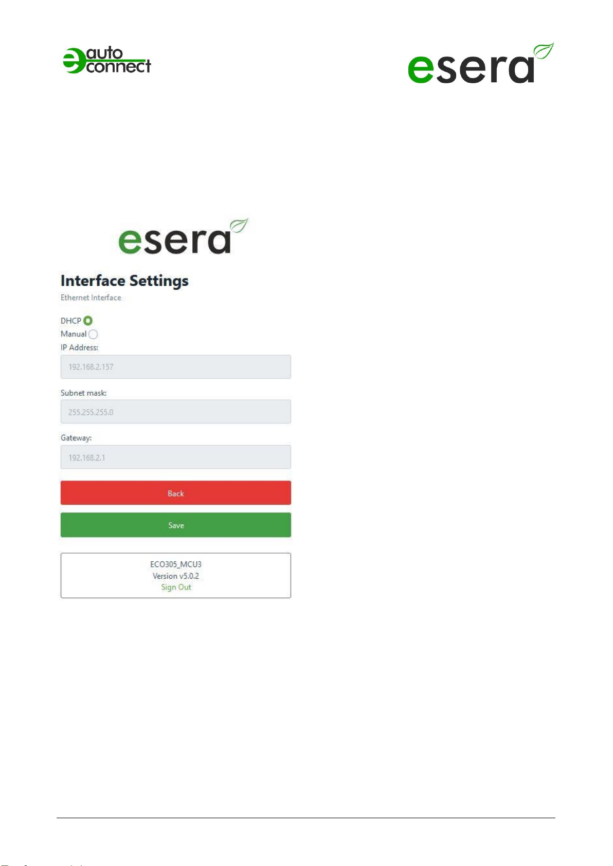
18 ETHERNET INTERFACE SETTINGS
Use the "Interface Setting" page to set the basic settings for the Maxi interface. The device IP address,
subnet mask and gateway IP address are set in
this menu.
These settings are also relevant for the web server and the ESERA ASCII text interface.
DHCP/Manual,
Operating mode IP address assignment
You can choose between automatic (DHCP) and
manual assignment of the IP address.
DHCP is activated in the delivery state.
IP Address
In case of automatic address assignment (DHCP),
the assigned IP addresses are displayed.
If the IP addresses are assigned manually, the
corresponding settings must be IP-Address,
Subnet mask and Gateway must be entered.
Save/Back
The "Save" button permanently saves the current
settings.
If you do not want to make any changes, press the
"Back" button.
Software version Ethernet interface/LogOut
Display of the software version of the Ethernet
interface installed on the device. The version of the
1-Wire firmware can be seen via the Config Tool 3.
Sign Out
By clicking the "Sign Out" button you will leave the
web server.
All rights reserved. Reprinting, including excerpts, not permitted without the express consent of ESERA GmbH.
Subject to technical changes. ESERA GmbH 2023
www.esera.de 12020-230_Manual Page 16 from 25
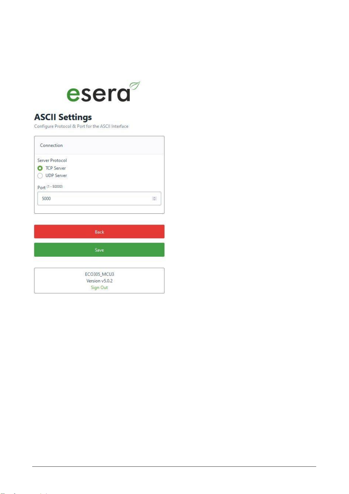
19 ASCII PROTOCOL SETTINGS
The ASCII Setting web page is used to configure the settings for the ESERA ASCII data interface (text
interface), e.g. for the Config Tool or the ECO DASHBOARD 100.
TCP Server/UDP Server
Here you can set the operating mode of the ASCII
data interface.
You can choose between TCP server and UDP
server.
Delivery state is TCP Server.
Port
The port for the ASCII data interface is assigned
here.
The port can be selected in the range of 1 - 5000.
The
default port is 5000, which
is the default setting for the ESERA Config Tool 3
and the ESERA ECO DASHBOARD 100.
Save/Back
The "Save" button permanently saves the current
settings.
If you do not want to make any changes, press the
"Back" button.
Software version Ethernet interface/LogOut
Display of the software version of the Ethernet
interface installed on the device. The version of the
1-Wire firmware can be seen via the Config Tool 3.
Sign Out
By clicking the "Sign Out" button you will leave the
web server.
Art. No. 12020-230
All rights reserved. Reprinting, including excerpts, not permitted without the express consent of ESERA GmbH.
Subject to technical changes. ESERA GmbH 2023
www.esera.de 12020-230_Manual Page 17 from 25
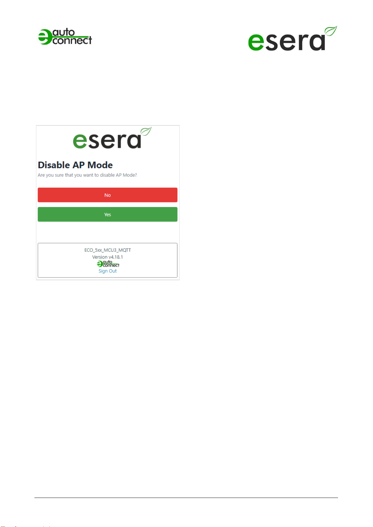
20 DISABLE AP MODE
In addition to a LAN interface, the ECO Gateway also has a connectable WLAN access point that you can
use to connect for configuration and data communication.
The access point is activated via a button on the device interface. For details, see above, under point 4.
Disable AP Mode
Yes/No
To turn off the WLAN access point, press the "Yes"
button.
Press the "No" button to exit the menu without
making any changes.
Software version Ethernet interface/Log Out
Display of the software version of the Ethernet
interface installed on the device. The version of the
1- Wire firmware can be seen via the Config Tool 3.
Sign Out
By clicking the "Sign Out" button you will leave the
web server.
All rights reserved. Reprinting, including excerpts, not permitted without the express consent of ESERA GmbH.
Subject to technical changes. ESERA GmbH 2023
www.esera.de 12020-230_Manual Page 18 from 25
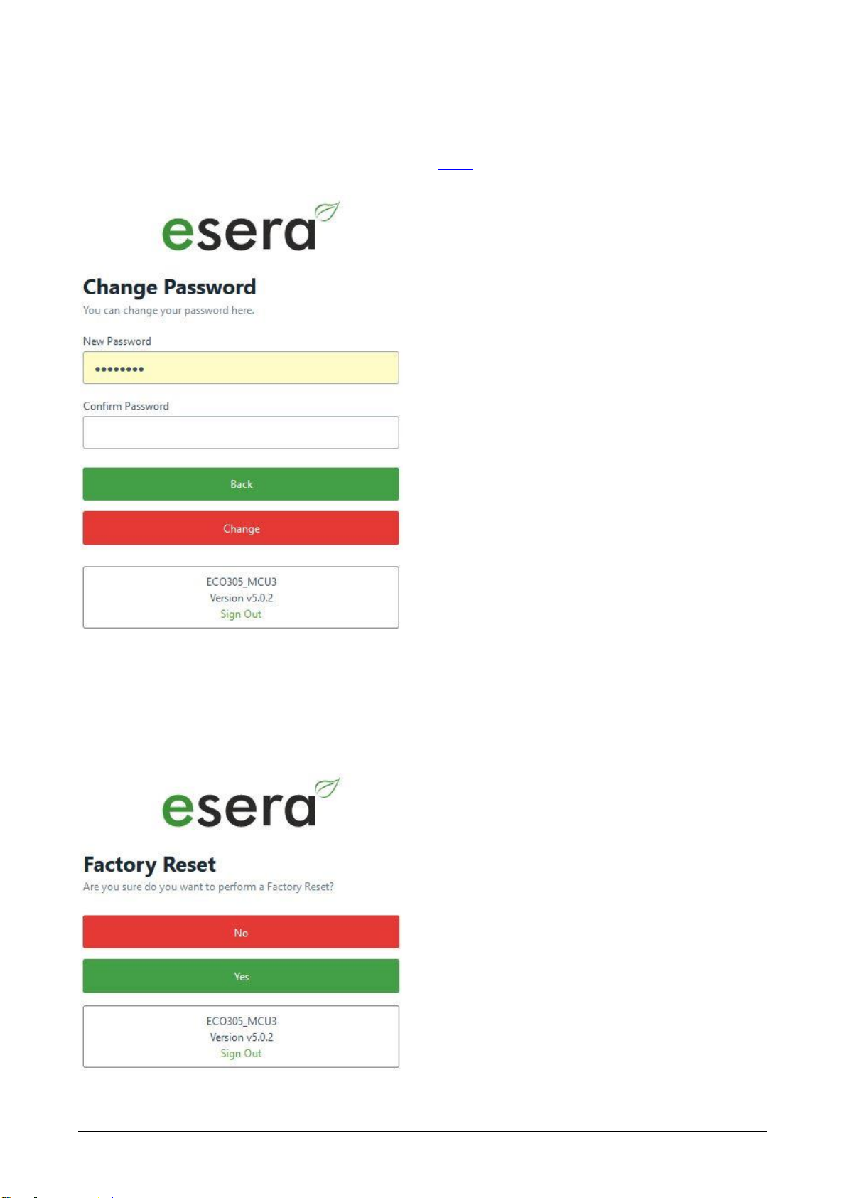
21 WEBSERVER, CHANGE PASSWORD
Use the "Change Password" page to set your individual access password.
Important
Please change the access password with the first login! Use a secure password if possible. What is a secure
password? Here are tips for creating a strong password: https://de.wikipedia.org/wiki/Passwort. Keep the
password in a safe place.
22 WEBSERVER, FACTORY RESET
Use the Factory Reset web page to clear all your settings and restore the interface to factory defaults.
NOTE
No changes are made to the I/O section, e.g. 1-Wire or eBus, settings.
Change Password
Here you enter the new access password for the
web server twice.
Save/Back
The "Save" button permanently saves the current
settings.
If you do not want to make any changes, press the
"Back" button.
Software version Ethernet interface/Log Out
Display of the software version of the Ethernet
interface installed on the device. The version of the
1-Wire firmware can be seen via the Config Tool 3.
Sign Out
By clicking the "Sign Out" button you will leave the
web server.
Factory Reset
Do you really want to delete all Ethernet Interface
settings and reset them to factory defaults?
If yes, press the "Yes" button.
Otherwise press the "No" button. This will also exit
the menu.
Software version Ethernet interface/Log Out
Display of the software version of the Ethernet
interface installed on the device. The version of the
1- Wire firmware can be seen via the Config Tool 3.
Log Out
Click on the "Sign Out" button to exit the web
interface.

Art. No. 12020-230
All rights reserved. Reprinting, including excerpts, not permitted without the express consent of ESERA GmbH.
Subject to technical changes. ESERA GmbH 2023
www.esera.de 12020-230_Manual Page 19 from 25
23 WEBSERVER, eBus FIRMWARE UPDATE
Via this web page you can update the firmware of the eBus section of the ECO Gateway. This replaces the
possibility to perform an update via the Config Tool.
eBus firmware update
Update procedure
1. Firmware file
First download the new firmware via the download
directory of the Config Tool 3 or the ESERA
website (www.esera.de).
Via the button "Firmware File" you can select the
new firmware version from your computer or tablet.
Select file
Use the "Upload" button to copy the new firmware
version to the interface of the ECO Gateway.
You can see the progress of the upload by the
progress bar.
2. Start firmware update
Now you will be asked if you really want to start the
firmware update.
Pressing "Yes" starts the update. The progress is
displayed via a progress bar.
With "No" no update is performed and the menu is
left.
Software version Ethernet interface/Log Out
Display of the software version of the Ethernet
interface installed on the device. The version of the
1- Wire firmware can be seen via the Config Tool
3.
Log Out
Click on the "Sign Out" button to exit the web
interface.

All rights reserved. Reprinting, including excerpts, not permitted without the express consent of ESERA GmbH.
Subject to technical changes. ESERA GmbH 2023
www.esera.de 12020-230_Manual Page 20 from 25
24 WEBSERVER, INTERFACE FIRMWARE UPDATE
Via this web page you can update the Ethernet firmware interface of the ECO Gateway.
NOTE
With the update of the interface no changes are made to the I/O / 1-Wire side of the
ECO Gateway.
Firmware file
First download the new firmware from the ESERA
website (www.esera.de).
Via this button "Firmware File" you can select the
new firmware file from your computer or tablet.
Upload
Use the button "Upload" to copy the new firmware
file into the interface of the ECO controller.
You can see the progress of the upload by the
progress bar.
Start firmware update
Now you will be asked if you really want to start the
firmware update.
Pressing "Yes" starts the update. The progress is
displayed via a progress bar.
With "No" no update is performed and the menu is
left.
Clicking the "No" button will cancel the update and
you will exit this menu.
Software version Ethernet interface
Display of the software version of the Ethernet
interface installed on the device. The version of the
1- Wire firmware can be seen via the Config Tool 3.
Log Out
Click on the "Sign Out" button to exit the web
interface.
Other manuals for ECO 305
1
This manual suits for next models
1
Table of contents
Other esera Gateway manuals


Popular Gateway manuals by other brands

RTA
RTA 460PSMS-N700 Product user guide

olympia electronics
olympia electronics GR-7602 quick start guide

Beam
Beam Man Down RST410 Configuration guide

ZyXEL Communications
ZyXEL Communications P-660HN-51 - quick guide

Rainforest Automation
Rainforest Automation EAGLE-200 quick start guide

Alcatel-Lucent
Alcatel-Lucent OmniAccess 8550 Brochure & specs


