manuals.online logo
Brands
  1. Home
  2. •
  3. Brands
  4. •
  5. ESI
  6. •
  7. Measuring Instrument
  8. •
  9. ESI 688 PREMIUM User manual

ESI 688 PREMIUM User manual

Safety
International Safety Symbols
This symbol, adjacent to another symbol or terminal, indicates the user must refer
to the manual for further information.
This symbol, adjacent to a terminal, indicates that, under normal use, hazardous
voltages may be present
Double insulation
SAFETY NOTES
Do not exceed the maximum allowable input range of any function
Do not apply voltage to meter when resistance function is selected.
Set the function switch OFF when the meter is not in use.
WARNINGS
Set function switch to the appropriate position before measuring.
When measuring volts do not switch to current/resistance modes.
When changing ranges using the selector switch always disconnect the test leads from
the circuit under test.
Do not exceed the maximum rated input limits.
CAUTIONS
Improper use of this meter can cause damage, shock, injury or death. Read and
understand this user manual before operating the meter. Always remove the test leads
before replacing the battery. Inspect the condition of the test leads and the meter itself for
any damage before operating the meter. Repair or replace any damage before use.
Use great care when making measurements if the voltages are greater than 25VAC rms or
35VDC. These voltages are considered a shock hazard. Remove the battery if the meter is
to be stored for long periods.
Always discharge capacitors and remove power from the device under test before
performing Diode, Resistance or Continuity tests.
Voltage checks on electrical outlets can be difficult and misleading because of the
uncertainty of connection to the recessed electrical contacts. Other means should be used
to ensure that the terminals are not "live".
If the equipment is used in a manner not specified by the manufacturer, the protection
provided by the equipment may be impaired.
Input Limits
Function
Maximum Input
A
80A DC/AC
V DC, V AC
600V DC/AC
Frequency, Resistance, Diode, Continuity ,
Capacitance Test
250V DC/AC
Temperature (℃/℉)
250V DC/ AC
#688 PREMIUM True
RMS Low Current
Clamp Meter
Meter Description
1. Current clamp
2. Clamp trigger
3. Rotary Function swith
4. Data Hold button
5. Back Light button
6. LCD display
7. MODE select button
8. PEAK button
9. MAX/MIN button
10. Relative button
11. COM input jack
12. V ΩCAP TEMPHz jack
1. AC DC AC (alternating current)
and DC (direct currrent)
2. Minus sign
3. 8.8.8.8 5000 count (0 to 4999) measurement
reading with 51 segments Analog Bargraph
4. AUTO AutoRange mode
5. Relative mode
6. Diode test mode
7. •))) Audible Continuity
8. H Data Hold mode
9. ℃,℉,,m,V,A,K,M,Ω,Units of measure list
10. Hz % Frequency/duty cycle test mode
11.MAX MIN MAX/MIN Hold mode
12.Pmax Pmin Pmax Pmin Hold mode
Specifications
Function
Range & Resolution
Accuracy (% of reading)
DC Current
5000mA DC
± (2.8% + 20 digits)
80.0 A DC
± (3% + 8 digits)
DC Current ranges specified from 5% to 100% of range
AC Current
(50/60Hz)
5000mA AC
± (3.0% +20digits)
80.0A AC
± (3.0% + 8 digits)
AC Current ranges specified from 5% to 100% of range
DC Voltage
500.0 mVDC
± (0.8% + 5 digits)
5.000 VDC
± (1.5% + 2digits)
50.00 VDC
500.0 VDC
600 VDC
± (2 % + 2 digits)
AC Voltage
(50/60Hz)
500.0 mVAC
± (1% + 10 digits)
5.000 VAC
± (1.5% + 5 digits)
50.00 VAC
500.0 VAC
600VAC
± (2.0% + 5 digits)
AC Voltage ranges specified from 5% to 100% of range
Resistance
500.0 Ω
± (1.0% + 4 digits)
5.000KΩ
± (1.5% + 2 digits)
50.00KΩ
500.0KΩ
5.000MΩ
± (2.5% + 3 digits)
50.00MΩ
± (3.5% + 5 digits)
Capacitance
50.00nF
(5.0% reading + 20 digits)
500.0nF
(3% reading + 5 digits)
5.000μF
50.00μF
500.0μF
(4.0% reading + 10 digits)
5mF
(5.0% reading + 10 digits)
Frequency
10Hz-100kHz
Sensitivity:100V(<50Hz);50V(50 to
400Hz;15V(401Hz to 100kHz)
(1.5% reading + 2 digits)
Temp
(type-K)
(probe accuracy
not included)
-20 to 760C
(3%rdg+5C)
-4 to1400F
(3%rdg+9F)
NOTE:
Accuracy is stated at 65oF to 83oF (18oC to 28oC) and less than 75% RH.
(2)
Clamp size Opening 0.75" (19mm) approx
Diode Test Test current of 0.3mA typical; Open circuit voltage <3.3V DC typical.
Continuity Check Threshold <50; Test current < 0.6mA
Low Battery Indication “” is displayed
Overrange Indication “OL”” is displayed
Measurements Rate 2 per second, nominal
Input Impedance 10M(VDC and VAC)
Display 5000 counts LCD
AC Current 50-60Hz (TRMS AAC)
AC Voltage bandwidth 50-60Hz ( TRMS VAC)
Operating Temperature 41 to 104oF (5 to 40oC)
Storage Temperature -4 to 140oF (-20 to 60oC)
Operating Humidity Max 80%
Storage Humidity <80%
Operating Altitude 7000ft. (2000meters) maximum.
Over voltage Category III 600V
Battery One 9V Battery
Auto OFF approx. 30 minutes
Dimensions/Weight 206x74x42mm/183g
Safety For indoor use and in accordance with EN-61010-1 2nd edition. It has
been evaluated and complies with overvoltage CAT III. Pollution degrees 2.
BUTTON DESCRIPTIONS
MODE BUTTON
To select DC/ACV,OHM/ Diode/Continuity/CAP, ℃/ ℉.
REL BUTTON
For DCA and Capacitance Zero & Offset adjustment.
Data Hold Button
To freeze the LCD meter reading, press the data hold button. The data hold button is
located on the left side of the meter (top button). While data hold is active, the H display
icon appears on the LCD. Press the data hold button again to return to normal operation
MAX/MIN
The meter displays the maximum or minimum value of the input in MAX/MIN mode. When
MAX/MIN is pressed for the first time, the meter displays the maximum value. When
MAX/MIN is pressed again, the meter displays the minimum value. When MAX/MIN is
pressed for the third time, MAX/MIN blinks and the meter displays the current input value.
To return to normal operation, press and hold MAX/MIN.
PEAK HOLD
The Peak Hold function captures the peak AC voltage or current. The meter can capture negative or
positive peaks as fast as 1 millisecond in duration.
1. Turn the function switch to the A or V position.
2. Use the MODE button to select AC. Allow time for the display to stabilize.
3. Press the PEAK button, Pmax will display. The display will now update and indicate the
highest positive peak.
4. Press the PEAK button again, Pmin will display. The display will now update and indicate the
lowest negative peak.
5. Press the PEAK button again, a blinking “MAX MIN” will appear. The meter will display the
present reading, but will continue to update and store the max and min reading.
6. Press and hold PEAK to return to normal operation.
Operation
NOTICES: Read and understand all warning and precaution statements listed in the
safety section of this operation manual prior to using this meter. Set the
function select switch to the OFF position when the meter is not in use.
AC/DC Current Measurements
WARNING: Ensure that the test leads are
disconnected from the meter before making current
clamp measurements.
1. Set the Function switch to the A, mArange.
2. Select AC or DC with the MODE button.
3. If the range of themeasured is not known,
select the higher Arange first then move to the lower
mA range if necessary.
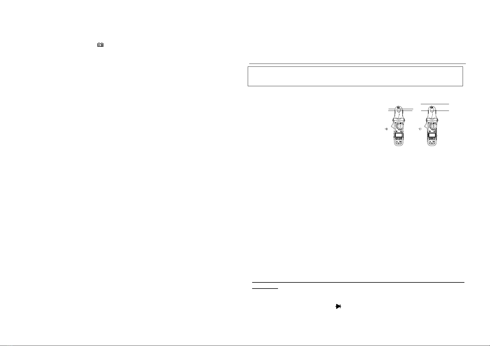
4. Press the trigger to open jaw. Fully enclose the clamp over the conductor wire to be
measured. Only one wire can bemeasured each time.
5. In DCA measuring mode, to ensure the reading is correct, please press REL button to
clear any residual reading on the LCD before measurement. This should be done
before each measurement.
The clamp meter LCD will display the reading.
AC/DC Voltage Measurements
1. Insert the black test lead into the negative COM terminal and the
red test lead into the positive Vterminal.
2. Set the function switch to the Vposition.
3. Select AC or DC with the MODE button.
4. Connect the test leads in parallel to the circuit under test.
5. Read the voltage measurement on the LCD display.
Resistance Measurements
Note: never attempt an Ohm reading on a live circuit. All power to the circuit must be
turned off.
1. Insert the black test lead into the negative COM terminal and the
red test lead into the positive terminal.
2. Set the function switch to the •))) position.
3. Touch the test probe tips across the circuit or component under
Test. It is best to disconnect one side of the device under test so
the rest of the circuit will not interfere with the resistance reading.
4. For resistance measurements, read the resistance on the LCD display.
5. For continuity measurements, press the mode button until the •))) appears.
6. Follow the same instructions as above - for Continuity tests, if the resistance is < 50, a
tone will sound.
Diode Measurements
1. Insert the black test lead banana plug into the negative COM jack and the red test lead
banana plug into the positive DIODE jack.
2. Turn the rotary switch to the •))) position.
3. Press the MODE button until “ “ appears in the display.
4. Touch the test probes to the diode under test. Forward voltage will indicate 0.4V to
0.7V. Reverse voltage will indicate “OL”. Shorted devices will indicate near 0mV and
an open device will indicate “OL” in both polarities.
Capacitance Measurements
WARNING: To avoid electric shock, disconnect power to the unit under test and
discharge all capacitors before taking any capacitance measurements. Remove the
batteries and unplug the line cords.
1. Set the rotary function switch to the CAP position.
2. Insert the black test lead banana plug into the negative COM jack.
Insert the red test lead banana plug into the positive Vjack.
3. Touch the test leads to the capacitor to be tested.
4. Read the capacitance value in the display
Frequency measurements - AC Only
1. Set the rotary function switch to the “Hz” position.
2. Insert the black lead banana plug into the negative COM jack and the red test
lead banana plug into the positive Vjack.
3. Touch the test probe tips to the circuit under test.
4. Read the frequency on the display.
Temperature Measurements
WARNING: To avoid electric shock, disconnect both test probes from any source of
voltage before making a temperature measurement.
1. Set the function switch to TEMP.
2. Insert the Temperature Probe into the negative COM and the Vjacks, making sure to
observe the correct polarity.
3. Touch the Temperature Probe head to the material surface you intend to measure.
Keep the probe touching the part under test until the reading stabilizes (about 30
seconds).
4. Read the temperature in the display. The digital reading will indicate the proper
decimal point and value.
WARNING: To avoid electric shock, be sure the thermocouple has been removed before
changing to another measurement function
Battery Replacement
1. Remove the one rear Phillips head screw
2. Open the battery compartment
3. Replace the Requires One 9V battery
4. Re-assemble the meter
WARRANTY INFORMATION:
This product is warranted to be free of defects for one year. If this product fails during the
first 12 months due to faulty material or workmanship, it will be replaced or repaired free of
charge, at the discretion of the manufacturer.
NOTE: this one year warranty does not cover accidental or intentional abuse.
For warranty service and coverage, please return this product to your supplier for
processing and evaluation. OR, return it directly to:
Electronic Specialties, Inc.
139 Elizabeth Ln.
Genoa City, WI 53128
262-279-1400
www.esitest.com
Red Black Black Red
Probe Probe Probe Probe
Forward test Reverse test

Other ESI Measuring Instrument manuals

ESI VideoBridge 2150 User manual

ESI

ESI VideoBridge 2150 User manual

ESI 2100 VideoBridge User manual

ESI

ESI 2100 VideoBridge User manual

Popular Measuring Instrument manuals by other brands

PCE Instruments PCE-BTM 2000A user manual

PCE Instruments

PCE Instruments PCE-BTM 2000A user manual

Teledyne 430 user manual

Teledyne

Teledyne 430 user manual

Lutron Electronics MG-3OO2 Operation manual

Lutron Electronics

Lutron Electronics MG-3OO2 Operation manual

ALPA PICKall manual

ALPA

ALPA PICKall manual

Nikon RifleHunter 550 instruction manual

Nikon

Nikon RifleHunter 550 instruction manual

intellic EFAS user guide

intellic

intellic EFAS user guide

STIEBEL ELTRON SOM WMZ SOL Operation and installation

STIEBEL ELTRON

STIEBEL ELTRON SOM WMZ SOL Operation and installation

PCB Piezotronics 1515-110-03A Installation and operating manual

PCB Piezotronics

PCB Piezotronics 1515-110-03A Installation and operating manual

Welch Allyn REF 29400 Directions for use

Welch Allyn

Welch Allyn REF 29400 Directions for use

Honeywell C7355B Mounting instructions

Honeywell

Honeywell C7355B Mounting instructions

Pfeiffer Vacuum PBR 260 operating instructions

Pfeiffer Vacuum

Pfeiffer Vacuum PBR 260 operating instructions

RR Mechatronics STARRSED TL installation manual

RR Mechatronics

RR Mechatronics STARRSED TL installation manual

General MMD900 user manual

General

General MMD900 user manual

GEORGE FISCHER Signet 5090 manual

GEORGE FISCHER

GEORGE FISCHER Signet 5090 manual

Tektronix P6248 instructions

Tektronix

Tektronix P6248 instructions

MR MSENSE BM operating instructions

MR

MR MSENSE BM operating instructions

UEi DMG100 instruction manual

UEi

UEi DMG100 instruction manual

Eclipse VeriFlame 5600 instruction manual

Eclipse

Eclipse VeriFlame 5600 instruction manual

manuals.online logo
manuals.online logoBrands
  • About & Mission
  • Contact us
  • Privacy Policy
  • Terms and Conditions

Copyright 2025 Manuals.Online. All Rights Reserved.