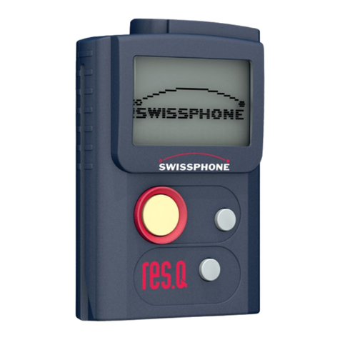
EsiWelma TUS40-20 User manual

Type / No. Rev. Date Page Total pages
EW082.695_en 5 02 August 2010 1
28
EsiWelma s.r.l.
HANDHELD TERMINAL FOR MONITORING
AND SETTING UR.20.. SENSORS
Terminal Unit
TUS40-20
INSTRUCTION MANUAL

Type / No. Rev. Date Page Total pages
EW082.695_en 5 02 August 2010 2
28
EsiWelma s.r.l.
CONTENTS
1GENERAL
.................................................................................................................................................3
1.1 M
EANING OF SYMBOLS
.......................................................................................................................3
1.2 H
AZARDOUS GAS THRESHOLD
..........................................................................................................3
2DESCRIPTION OF TERMINAL UNIT
..............................................................................................5
3INSTALLATION
.......................................................................................................................................8
3.1 I
NSTALLATION OF THE
TUS40-20
T
ERMINAL
U
NIT
.......................................................................8
3.2 T
YPES OF DETECTOR INSTALLATION FOR CORRECT MONITORING
.............................................10
4USING THE TERMINAL UNIT
..........................................................................................................11
4.1 O
PERATING MODES
..........................................................................................................................11
4.2 M
ONITORING MODE
...........................................................................................................................12
4.3 S
ETTING MODE
..................................................................................................................................13
4.4 C
ALIBRATION MODE
..........................................................................................................................14
4.5 C
ALIBRATING THE SENSOR
..............................................................................................................15
4.6 O
UTPUT TEST MODE
.........................................................................................................................18
4.7 4…20
M
A
SIGNAL CALIBRATION MODE
...........................................................................................19
4.8 T
ROUBLESHOOTING
..........................................................................................................................21
4.9 S
ENSOR OPERATION CHECK
............................................................................................................22
4.10 R
ESIDUAL LIFE
...............................................................................................................................23
4.11 C
HANGING THE CONTRAST ON THE DISPLAY
.............................................................................23
5INSTALLATION DATA
........................................................................................................................24
6ROUTINE CHECKS
.............................................................................................................................25

Type / No. Rev. Date Page Total pages
EW082.695_en 5 02 August 2010 3
28
EsiWelma s.r.l.
1 GENERAL
This chapter provides some information on the characteristics of the gases and on the
installation criteria for gas detection devices before the description of the TUS40-20 terminal
unit.
It is not essential to read this chapter to install and commission the terminal unit
described in this manual. Readers who already know the subject can skip this part.
1.1 Meaning of symbols
The symbols used in this manual have the following meaning:
•ppm: Parts Per Million of concentration of gas in the air
•L.E.L%: Lower Explosive Limit
•%VOL: concentration of gas measured in percentage by volume
•D: Detector
•t: threshold limit value
•Pr: pre-alarm threshold
•1t: alarm threshold one
•2t: alarm threshold two
•FA: fail
1.2 Hazardous gas threshold
For gases and for combustible vapours, the hazardous conditions begin from a threshold
called "Lower Explosive Limit" (LEL) that is the lowest concentration (percentage) of a gas
in air capable of producing a flash of fire in presence of an ignition source. This threshold
changes from gas to gas. The Lower Explosive Limits for some of the most common
gases are shown in the table below.
LEL (100%)
GAS ppm %VOL
METHANE (CH4) 50,000 5%
ISOBUTANE (iso-C4H10) 18,000 1.8%
BUTANE (C4H10) 18,600 1.86%
LPG 19,000 1.9%
HYDROGEN (H2) 40,000 4%
Table 1.1
For toxic gases such as carbon monoxide (CO), the hazard level must be considered also in
relation to the duration of the person's exposure in the polluted environment. The table
below shows risks from exposure to carbon monoxide (CO). Carbon monoxide is generated
wherever combustion occurs and the lungs rapidly absorb it and spread it through the
pulmonary alveolus where it reversibly binds with the haemoglobin as “carboxyhaemoglobin”
(COHb). It is also colourless and odourless so it is not naturally detected. This is why CO-
specific detection devices are necessary.

Type / No. Rev. Date Page Total pages
EW082.695_en 5 02 August 2010 4
28
EsiWelma s.r.l.
COHb in the bloodstream has the following effects on healthy adults.
% COHb EFFECTS
0.3-0.7 Normal amount in non-smokers from the endogenous production of CO
0.7- 2.9 No detectable symptoms
2.9-4.5 Cardiovascular disorders in patients suffering from heart disease
4-6 Usual levels in smokers, some physical impairment in psychomotor tests
7-10 Ailments in patients without heart disease (increase in cardiac output and in
blood flow in coronary arteries)
10-20 Slight headache, weakness, possible effect on foetus
20-30 Strong headache, nausea, loss of movement in hands
30-40 Strong headache, irritability, confusion, loss of vision, nausea, muscle
weakness, dizziness
40-50 Convulsions and loss of consciousness
60-70 Coma, respiratory arrest, death
Table 1.2
This issue is covered in other similar tables and a wide range of literature. In its document,
"Air quality for CO", the US department of Health, Education and Welfare refers to an
observed weakening in vision observed with 3% of COHb and in other psychomotor tests
with 5% of COHb.
More recently, subjects exposed to a dose of 100 ppm CO for one hour have shown a loss
of motor skills.
ppm % VOL LEL % (methane gas)
1,000,000 100 impossible combustion
100,000 10
100 Lower Explosive Limit
40
10,000 1
20
10
5
1,000 0.1
100 0.01
10 0.001
1 0.0001
Fig. 1.1
Possible combustion
range
Limit value range of
gas detectors

Type / No. Rev. Date Page Total pages
EW082.695_en 5 02 August 2010 5
28
EsiWelma s.r.l.
2 DESCRIPTION OF TERMINAL UNIT
The TUS40-20 is a terminal unit for monitoring and setting the UR.20. sensors and consists of:
theTUS40 handheld terminal
the UIC20 junction card
the 3m long CBL01 coiled cable
the two units communicate through a dedicated master protocol.
The TUS40-20 terminal unit is necessary when a mobile monitoring system is required and/or
for different settings of the gas detection threshold limit values from the ones that can be set
using the DIP switch; it is also necessary for recalibrating sensors if standard factory
calibration gas cylinders are not used.
NOTE: the words "detector" and "sensor" are used without distinction throughout this document
and have the same meaning, except where this may create ambiguity.
The system structure is shown in Fig. 2.1.
Fig. 2.1 –
Terminal unit for monitoring and setting UR.20.. sensors
Handheld
terminal
Junction
card
Coiled cable

Type / No. Rev. Date Page Total pages
EW082.695_en 5 02 August 2010 6
28
EsiWelma s.r.l.
Under normal operating conditions (monitoring) the handheld terminal receives the information
relating to measurements taken by the detector and the alarm status established by the
threshold limit values. Three threshold limit values and one fail condition can be defined, and
they are respectively called:
•pre-alarm: Preall.
•alarm threshold one: Treshold1
•alarm threshold two: Treshold2
•device failure: Fail
The UR.20.. detectors come in four models (E, S, I, L) and their use depends on the protection
mode required:
Application Protection mode Part number
Classified (hazardous)
areas
(ATEX certification
required)
Group II
Category 2G
Ex d IIC T6
T
AMB
: -20 °C
÷
+50 °C
UR.20.E
Group II
Category 3G
Ex nA d IIC T6
T
AMB
: -20 °C
÷
+50 °C
UR.20.S
Unclassified (non-
hazardous) areas
(ATEX certification is
not required)
Heavy-duty applications
Construction conforming to
Ex d requirements
IP65
UR.20.I
Standard applications
Construction conforming to
Ex nA requirements
IP55
UR.20.L
Tab.2.1 – Gas sensors: available models
In turn, each model (E, S, I, L) has two possible executions:
•with Standard sensor (code S: UR.20S.)
•with Professional sensor (code P: UR.20P.)
Two types of sensors are commonly used for the gases that most frequently require detection
(methane, LPG, gasoline vapours, carbon monoxide etc.): catalytic (Pellistor) and
electrochemical cell. In both cases, the Professional execution is differentiated from the
Standard execution by the use of sensors that are based on the same operating principle as
the others but that over time have more measurement stability and higher poison resistance to
the continuous presence of gas.

Type / No. Rev. Date Page Total pages
EW082.695_en 5 02 August 2010 7
28
EsiWelma s.r.l.
As you can see in the table below, the part number includes several fields for rapid
identification in order to facilitate the choice of the detector according to the technical features
described above:
Available
models
Models on
request
For other Gases, on request, please contact Customer Service.
Detectable Gas
Sensing Element
Standard
Catalytic
Pellistor
Catalytic
(Professional)
2-terminal
Electr.
Cell
(Standard)
3-terminal
Electr.
Cell
(Professional)
Semiconductor
(1 or 2-
thresholds
applications)
Non
Dispersive
infrared
Methane URG20SL URG20PL --- --- URG20TL ---
LPG URP20SL URP20PL --- --- URP20TL ---
CO --- --- URO20SL URO20PL URO20TL ---
Gasoline
Vapours
URB20SL URB20PL --- --- URB20TL ---
O
2
--- --- URS20SL --- --- ---
CO
2
--- --- --- --- --- URD20SL
Acetylene URL20SL URL20PL --- --- URL20TL
Hydrogen URI20SL URI20PL --- --- URI20TL
Ammonia URM20SL URM20PL --- --- URM20TL
Propane URC20SL URC20PL --- --- URC20TL
Octane URT20SL URT20PL --- --- URT20TL
Ethyl Alcohol URE20SL URE20PL --- --- URE20TL
Tab. 2.2 – Gas detector part numbers

Type / No. Rev. Date Page Total pages
EW082.695_en 5 02 August 2010 8
28
EsiWelma s.r.l.
3 INSTALLATION
3.1 Installation of the TUS40-20 Terminal Unit
The TUS40 handheld terminal is constructed in plastic housing and it plugs into the junction
box via the coiled cable to be powered by the UR.20.. sensor.
A fold-out bar on the back of the TUS40 handheld terminal can be used to place it at a
convenient tilt on a minimum surface area of 220x130 mm. Knurling at the sides of the
keypad ensures an easy and secure grip.
The TUS40-20 terminal unit must be connected with the sensor power off; follow product
and/or installation instructions before opening the sensor cover. Proceed as follows to
connect the TUS40-20 terminal unit:
1. Make sure the area is clear of gas and that the sensor is not powered up
2. Open the UR.20 sensor cover (Fig.3.1)
3. Identify the position of the CN4 connector on the diagram (Fig. 3.2)
4. Plug the junction card into the socket, making sure it is properly lined up with the
contacts (Fig. 3.3), then plug the cable and handheld terminal into the junction card
RJ45 connector.
5. Power up the sensor
6. Wait for the handheld terminal display to switch on; it will show a row of asterisks,
followed by the sensor status page (Fig. 4.1 and 4.2)
7. Wait for the end of the warm-up phase (preheating, Fig. 4.3)
8. The handheld terminal will then show the basic display (Monitoring Mode).
It is now possible to operate with the handheld terminal (Fig. 4.4).
The direction of the detector must always have the sensor facing downwards
Fig. 3.1 – Removing the cover of the UR20 sensors
Turn the screw cover
anticlockwise Remove the fastening
screws of the cover

Type / No. Rev. Date Page Total pages
EW082.695_en 5 02 August 2010 9
28
EsiWelma s.r.l.
CN4 connection
Fig. 3.2 – CN4 position
Fig. 3.3 – TUS40 terminal plug-in operation
Warning:
Properly align the female and
male CN4 connector with the
PCB side of the UIC20 junction
card to the outside of the main
board of the sensor.

Type / No. Rev. Date Page Total pages
EW082.695_en 5 02 August 2010 10
28
EsiWelma s.r.l.
3.2 Types of detector installation for correct monitoring
The detectors must be wall-mounted at whatever height is appropriate for the type of gas to
be detected (Fig. 3.4).
Fig. 3.4 – Possible detector positions
Use the information below to correctly position the detectors:
•20 cm from the floor to detect gases heavier than air (LPG or Gasoline Vapours)
•20 cm from the ceiling to detect gases lighter than air (Methane)
•midway between floor and ceiling (1.5 - 2 m) to detect gases as heavy as air (CO)
The TUS40-20 termination kit comes with a 3 m coiled cable so it can operate correctly
even at a considerable height and distance from the sensor.
The connection cable must not be stretched to its full length when it is plugged in to
make sure it does not disconnect from the junction card.
Do not use extension cords on the cables and do not extend the cables themselves by
cutting and joining as this may adversely affect the proper operation and safety of the
device.
To guarantee correct gas detection, in addition to the instructions above, the positions of the
detectors must take into consideration the following specific installation guidelines:
The detector must be mounted:
•where accidental gas leakages are possible
•at least 1.5 metres from heat sources
•not in spaces where ventilation is poor and where gas pockets may form
•at least 1.5 metres from vent holes
•away from hindrances to natural gas flow
•in environments with a temperature range of -20°C to 50°C and relative humidity below
90% (non-condensing).
20 cm
from the ceiling
20 cm from
the floor
1,5-2 m
from the
floor
URG40.. (Methane)
URO40.. (CO)
URP40.. (LPG) URB40.. (Gasoline vapours)

Type / No. Rev. Date Page Total pages
EW082.695_en 5 02 August 2010 11
28
EsiWelma s.r.l.
4 USING THE TERMINAL UNIT
After the wiring and connections between the sensor and the TUS40-20 terminal unit are
complete, visually inspect them to make sure they are correct, ensure you are operating in a
safe zone, then power up the sensor.
4.1 Operating modes
Only connect and disconnect the TUS40-20 junction box to and from the sensor if the
sensor power is off, to avoid connection errors. This makes it possible to correctly activate
communication between the two devices and their alignment.
The TUS40-20 terminal unit can be used for several calibrations and checks:
•Monitoring or normal operating mode
•Alarm thresholds setting mode
•Sensor calibration mode
•Output test mode
•4…20mA signal calibration mode
When the unit is switched on, the following display sequences will appear:
1. The backlighting will switch on and the following words will appear on the handheld
terminal display:
2. The display then shows the following, where x.xxx stands for the firmware version:
In this phase, the sensors begin the warm-up phase and the operation can take a few
minutes.
The display shows the following during the warm-up phase:
*
*
*
*
*
*
*
*
Fig. 4.1
*
*
E
S
I
W
E
L
M
A
*
*
U
R
2
0
v
e
r
s
x
.
x
x
x
Fig. 4.2
S
e
n
s
o
r
:
T
T
T
T
T
T
T
R
e
s
i d
u
a
l l i f
e
: S
S
S
S
T
A
T
E
: (
P
r
e
h
. )
C
o
n
c
e
n
t
. : Z
Z
Z
=
X
X
X
Fig. 4.3

Type / No. Rev. Date Page Total pages
EW082.695_en 5 02 August 2010 12
28
EsiWelma s.r.l.
4.2 Monitoring mode
At the end of the warm-phase, the sensor shows the following display:
Where:
TTTTTT = Abbreviation of sensor type
SSS= residual operational lifetime in weeks
YYYYYYYY = Abbreviation of sensor status
ZZZ= Unit of measure of the concentration (ppm for CO or LEL for explosive gases)
XXX= Concentration detected by the sensor
Abbreviations used for the sensor status:
(Preh.): only during Preheating
OK: during normal operation
Preall: if the sensor has exceeded the pre-alarm threshold
Threshold 1: if it has exceeded the 1
st
threshold
Threshold 2: if it has exceeded the 2
nd
threshold
Fail: if a fault of any kind is detected.
The abbreviation identifying the sensor is one of the following:
CAT_1 for type A catalytic sensors
CAT_2 for type B catalytic sensors
CAT_3 for type C catalytic sensors
CEL_4 for type A electrochemical cell sensors
CAT_5 for type D catalytic sensors
SEMIC_6 for type A semi-conductor sensors
SEMIC_7 for type B semi-conductor sensors
SEMIC_8 for type C semi-conductor sensors
CEL_9 for type B electrochemical cell sensors
CEL_10 for type C electrochemical cell sensors
CEL_11 for type D electrochemical cell sensors
NDIR_1 for type A non dispersive infrared sensors
NDIR_2 for type B non dispersive infrared sensors
In this phase, the handheld terminal constantly displays the concentration measured and
continues to update the value every few seconds.
S
e
n
s
o
r
:
T
T
T
T
T
T
T
R
e
s
i d
u
a
l l i f
e
: S
S
S
S
T
A
T
E
: Y
Y
Y
Y
Y
Y
Y
Y
C
o
n
c
e
n
t
. : Z
Z
Z
=
X
X
X
Fig. 4.4

Type / No. Rev. Date Page Total pages
EW082.695_en 5 02 August 2010 13
28
EsiWelma s.r.l.
4.3 Setting mode
With the UR20, setting is possible after the warm-up phase is complete.
Press the SETTING key to enter Setting Mode
The following operations are possible in setting mode:
1) Setting the alarm threshold limit values (useable in custom mode)
2) Setting the full scale set point of the device
3) Calibrating the sensor
Enter setting and the display will show the set point thresholds:
Where:
TTTTTTT = Abbreviation of sensor type
ZZZ = Unit of measure of the concentration (PPM, LEL or %)
XXX = Threshold limit values set in the configurable set point for each threshold
Threshold 1 is the pre-alarm threshold, Threshold 2 is the 1
st
alarm level and Threshold 3 is
the 2
nd
alarm level.
The cursor (an asterisk) starts out on the first line:
Use the UP and DOWN keys to scroll up to the previous line or down to the next line
Note: it is not possible to scroll beyond the first or the last line
Press ENTER to show the change threshold value display
Use the PLUS or MINUS keys to set the new threshold value.
After setting the new threshold value you can press these keys:
•ENTER to permanently memorise the threshold setpoints
•ESCAPE to go back to normal operating without memorising anything
(if the ENTER key was not pressed)
S
e
n
s
o
r
:
T
T
T
T
T
T
T
T
h
r
e
s
h
o
l d
1
: Z
Z
Z
=
X
X
X
*
T
h
r
e
s
h
o
l d
2
: Z
Z
Z
=
X
X
X
T
h
r
e
s
h
o
l d
3
: Z
Z
Z
=
X
X
X
Fig. 4.5
S
e
n
s
o
r
:
T
T
T
T
T
T
T
T
h
r
e
s
h
o
l d
1
: Z
Z
Z
=
X
X
X
T
h
r
e
s
h
o
l d
2
: Z
Z
Z
=
X
X
X
*
T
h
r
e
s
h
o
l d
3
: Z
Z
Z
=
X
X
X
Fig. 4.6
N
e
w
T
h
r
e
s
h
o
: Z
Z
Z
=
X
X
X
Fig. 4.7

Type / No. Rev. Date Page Total pages
EW082.695_en 5 02 August 2010 14
28
EsiWelma s.r.l.
4.4 Calibration mode
The UR20 is calibrated by two measurement values. The first of the two values is always
zero - no gas measured, make exception O
2
that in free air has a concentration of 20,9%;
the second is the factory-calibrated set point of:
•50% of LEL (mid scale) for explosive gases
•500 PPM (full scale) for toxic gases
•0,5% Vol. only for CO
2
sensor
•4,0% Vol. Only for O
2
Except for the infrared sensors, (see NDIR_1,2) that do not handle some of the parameters,
is possible view the sensor calibration values, pressing
1
in the Setting Mode. The display
will show the following:
Where:
TTTTTTT = Abbreviation of sensor type
XXXXX = Value in steps of the A/D converter of the 1
st
calibration set point
XXXXX = Value in steps of the A/D converter of the 2
nd
calibration set point
ZZZ = Units of the concentration (PPM or LEL)
KKK = Value of concentration
SSSS = Steps of the A/D converter equivalent to the measured value
Press ESC to return to Setting mode from this display
If the gas used comes in different concentrations from 50% LEL or 500 PPM, it is possible
to change the correspondence of the LEL percentage in the 2nd calibration set point.
Press key
2
from the Setting mode and the following display will appear:
Where:
ZZZ = Unit of measure of the concentration (PPM, LEL or %)
KKK = Value of concentration of the 2nd calibration set point
Press keys
0
to
9
to set the correspondence of the LEL (or PPM) percentage in the 2nd
calibration set point.
Lastly, press ENTER to memorise the set point value
Press ESC to return to Setting mode from this display
S
e
n
s
o
r
:
T
T
T
T
T
T
T
C
a
l . 0
=
X
X
X
X
X
C
a
l . m
a
x
=
Y
Y
Y
Y
Y
Z
Z
Z
=
K
K
K
A
D
C
=
S
S
S
S
Fig. 4.8
P
h
a
s
e
2
:
Z
Z
Z
=
K
K
K
Fig. 4.9

Type / No. Rev. Date Page Total pages
EW082.695_en 5 02 August 2010 15
28
EsiWelma s.r.l.
4.5 Calibrating the sensor
Hold down the KEY button for at least 5 seconds to enter this phase from the setting
mode. The display will show the following:
Press the
1
button to enter in the real calibration menu in Figure 4.13 and below.
Press the
3
button to displays a screen in Figure 3. 4.11 which shows the full scale of the
detector and the gas concentrations to which the calibrations were performed.
Press the
2
button for to see the following screen in Figure 4.12:
From this menu by press the
1
button it can be execute the reset, upon confirmation of
the calibration values to those inserted by the manufacturer of the sensor.
Press the
2
button for execute a supply interruption of the only sensor without resetting
the entire detector. After wait the preheating time.
From all the screens you can return to the Calibration mode by pressing ESC.
S
e
n
s
o
r
:
T
T
T
T
T
T
T
C
a
l i b
r
a
t
i o
n
P
o
i n
t
0
P
=
0
X
X
X
Fig. 4.13
1
)
C
a
l
i
b
r
a
t
i o
n
2
)
O
t
h
e
r
3
)
I n
f
o
Fig. 4.10
S
c
a
l
e
m
a
x
. p
p
m
=
2
0
0
0
0
0
c
a
l i b
r
. p
p
m
=
0
G
a
s
c
a
l
i b
r
. p
p
m
=
5
0
0
0
Fig. 4.11
1
)
F
a
c
t
o
r
y
c
a
l .
2
)
P
W
R
R
e
s
e
t
C
o
n
c
e
n
t
. : Z
Z
Z
=
X
X
X
Fig. 4.12

Type / No. Rev. Date Page Total pages
EW082.695_en 5 02 August 2010 16
28
EsiWelma s.r.l.
Two successive steps are required for calibration:
•Calibrating the zero point (
clean air for toxic and flammable gas, nitrogen for poison
gas such as CO
2
)
•Calibrating the factory-set concentration (default: 50% LEL for explosive gases, 500
PPM for CO, 5000 PPM for CO
2
, 4%vol for O
2
) as per the section above
At this point it is possible to press:
•ESCAPE to take the sensor back to normal operation
•ENTER to start up calibration of 0 (zero) set point in clean air (zero gas
concentration)
When the words In progress… show on the display, wait until the end of the procedure
At the end, if the calibrating procedure has been successful the display will show:
The top two lines stay the same, the third line shows:
0XXX= Steps of the A/D converter to read the sensing element.
The next line:
SSS = Steps applied to the electronic potentiometer (only for sensors that include this)
VVVV = Value read by the converter and expressed in steps, not in concentration
measuring unit.
The two values could be periodically updated throughout the procedure that can last for
many seconds (duration depends on the type of sensor).
At this point it is possible to press:
•ESCAPE to take the sensor back to normal operation
•ENTER to start up calibration at the default gas concentration (2
nd
set point)
If Zero calibration was not successful, the display will show Fail. Press ENTER to repeat the
zero calibration procedure.
If Zero calibration was successful, when ENTER is pressed, calibration at the default set
point will start up. The display will show:
S
e
n
s
o
r
:
T
T
T
T
T
T
T
C
a
l i b
r
a
t
i o
n
P
o
i n
t
0
P
=
0
X
X
X
I n
p
r
o
g
r
e
s
s
. . .
Fig. 4.14
S
e
n
s
o
r
:
T
T
T
T
T
T
T
C
a
l i b
r
a
t
i o
n
P
o
i n
t
0
P
=
0
X
X
X
O
k
: b
=
S
S
S
t
=
V
V
V
V
Fig. 4.15
S
e
n
s
o
r
:
T
T
T
T
T
T
T
C
a
l i b
r
a
t
i o
n
I I P
o
i n
t
P
=
0
X
X
X
Fig. 4.16

Type / No. Rev. Date Page Total pages
EW082.695_en 5 02 August 2010 17
28
EsiWelma s.r.l.
Apply the gas to the sensor at the default concentration and wait for about 3 minutes for
reading to stabilise the value on the third line of the display will stabilise. (WARNING: this is
always an absolute value).
At this point it is possible to press:
ESCAPE to take the sensor back to normal operation
ENTER to start up calibration at the gas concentration of the 2
nd
point
Calibration only takes a few seconds and the display will show In progress…
At the end, it will show:
If the point calibration has been successful, where:
VVVV = Values read by the converter and expressed in steps at point 0 and at the 2
nd
point.
Or:
At this point it is possible to press:
ESCAPE to take the sensor back to normal operation
ENTER to unconditionally repeat calibration of the 2
nd
point.
If a calibration error occurs, press ENTER and the display will show the calibration fail. To
return to the display as per Fig. 4.2, switch off the system, wait for at least ten seconds, then
power up again.
if the fault persists, the error shows again on the display as follows
S
e
n
s
o
r
:
T
T
T
T
T
T
T
C
a
l i b
r
a
t
i o
n
I I P
o
i n
t
P
=
0
X
X
X
O
k
: t
0
=
V
V
V
V
t
=
V
V
V
V
Fig. 4.17
S
e
n
s
o
r
:
T
T
T
T
T
T
T
C
a
l i b
r
a
t
i o
n
I I P
o
i n
t
P
=
0
X
X
X
F
a
i l : t
0
=
V
V
V
V
t
=
V
V
V
V
Fig. 4.18
F
a
i
l
:
W
r
o
n
g
C
a
l i b
r
a
t
i o
n
Fig. 4.19

Type / No. Rev. Date Page Total pages
EW082.695_en 5 02 August 2010 18
28
EsiWelma s.r.l.
4.6 Output test mode
During the warm-up phase only, enter the monitoring mode and press
9
to access a menu
where it is possible to directly test the outputs, or press
0
to access the 4…20mA
calibration procedure described in the relative paragraph.
The display will show the following:
WARNING: the 0XXX values shown on the fourth line are the values of the A/D converter
corresponding to the two calibration points of the sensor.
Press key:
1
To activate and deactivate the fail alarm relay output
2
To activate and deactivate the alarm relay output for exceeding the 2
nd
threshold
3
To activate and deactivate the alarm relay output for exceeding the 1
st
threshold
4
To activate and deactivate the pre-alarm relay output
To increase the output current on measurement terminals 3 and 4 up to 22mA
To decrease the output current on measurement terminals 3 and 4 down to 0mA
To exit output test mode and return to monitoring mode.
Note: for the functions relating to keys 1, 2, 3 and 4 it is necessary to have the UZR20.4 relay
card in the equipment.
The warm-up phase is suspended during output test mode and starts again after returning to
monitoring mode.
If no key is pressed for 5 minutes during output test mode, it automatically exits and returns
to monitoring mode.
C
a
l i
b
.
4
-
2
0
m
A
: 0
T
e
s
t
:
1
,
2
, 3
, 4
, +
, -
t 0
=
0
X
X
X
t
=
0
X
X
X
Fig. 4.20

Type / No. Rev. Date Page Total pages
EW082.695_en 5 02 August 2010 19
28
EsiWelma s.r.l.
4.7 4…20mA signal calibration mode
To execute this type of calibration, it is necessary to insert in series to the 4...20mA output an
instrument suitable for this magnitude and with a precision of at least 2% on the full scale.
Calibration consists of calibrating two points (one at 4mA, the other at 15 mA)
During the warm-up phase only, enter the monitoring mode and press
9
to enter a menu
where it is possible to directly test the relay outputs, or press
0
to enter the 4…...20mA
output calibration procedure.
The display will show the following:
The two fields XXXX are the A/D Converter values required to generate the output currents.
Press: or to vary the output that generates the 4mA with a delay of about 2
seconds.
Press the key to memorise calibration; the display will show that the new value has been
saved by changing as follows:
Press: or to vary the output that generates the 15mA with a delay of about 2
seconds.
Otherwise, press to terminate the procedure without memorising the new value.
C
a
l i b
.
4
-
2
0
m
A
: 4
m
A
4
=
X
X
X
X
1
5
=
X
X
X
X
Fig. 4.21
C
a
l i b
.
4
-
2
0
m
A
: 1
5
m
A
4
=
X
X
X
X
1
5
=
X
X
X
X
Fig. 4.22

Type / No. Rev. Date Page Total pages
EW082.695_en 5 02 August 2010 20
28
EsiWelma s.r.l.
Press the key to memorise calibration; the display will show the previous display as
confirmation that the new value has been saved:
To terminate the procedure press key .
The warm-up phase is suspended during 4...20mA calibration test mode and starts again
after returning to monitoring mode.
If no key is pressed for 5 minutes during 4...20mA output calibration mode, it automatically
exits from the calibration mode and returns to monitoring mode.
The device is automatically reset in all output modes, as shown in the following display:
C
a
l i b
.
4
-
2
0
m
A
: 4
m
A
4
=
X
X
X
X
1
5
=
X
X
X
X
Fig. 4.23
*
R
E
S
E
T
-
W
A
I T
*
Fig. 4.24
Table of contents

