ESK BOS2-CDM Series User manual

Ölabscheider
OS-CD und BOS2-CDM
Die genannten ESK-Komponenten sind Druckbehälter
und ausschließlich für die Anwendung in Kälteanlagen
bestimmt.
SieentsprechenderEG-Druckgeräterichtlinie2014/68/EU.
Eine Inbetriebnahme ist nur unter der Voraussetzung
zulässig, dass der Einbau entsprechend den gesetz-
lichen Vorschriften erfolgte. Alle Komponenten werden
entsprechend den geltenden Regeln konstruiert und
gefertigt. AD-Merkblätter; Druckgeräterichtlinie; EN 378
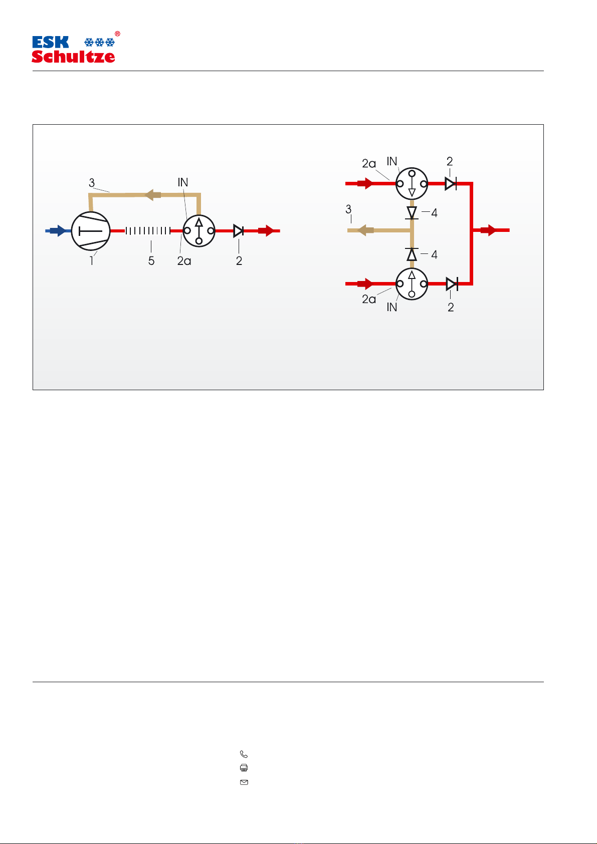
Anwendung
ESK-Ölabscheider OS-CD und BOS2-CDM sind für den Einsatz
mit den Kältemitteln R744 (CO2) und R410A freigegeben.
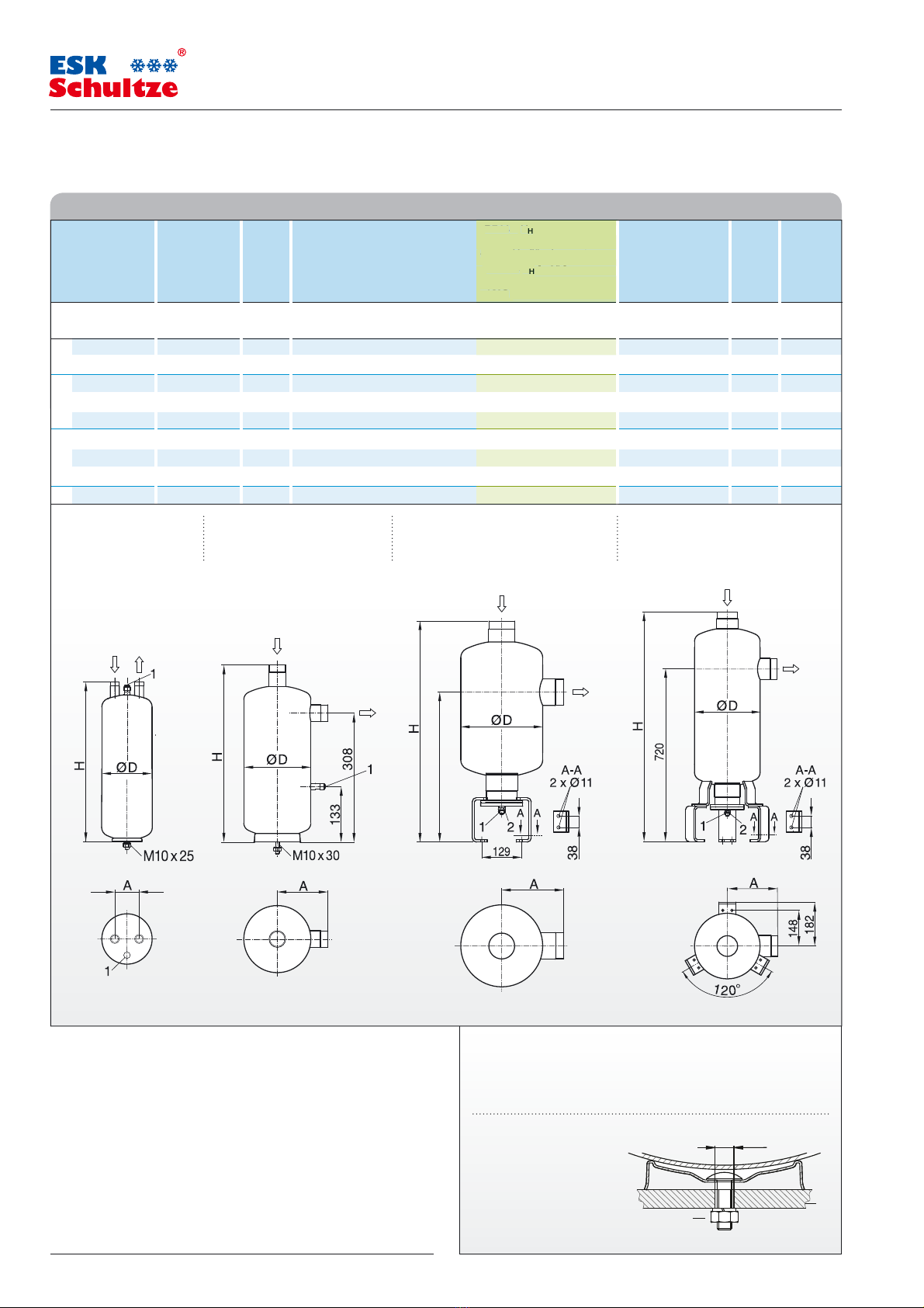
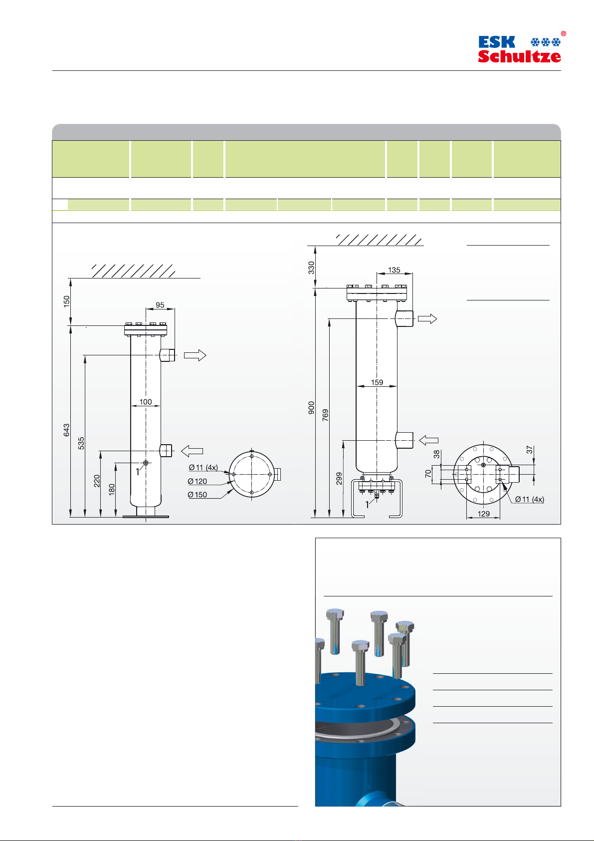
Technische Spezifikation
Max. zulässiger Betriebsüberdruck (PSmax)
in den Temperaturbereichen:
Typ: OS-CD
[1] Zul. Betriebstemperatur: 140 ... –10°C ϭPS1: Siehe Tabelle
[2] Zul. Betriebstemperatur: –10 ... – 40°C ϭP
S2: Siehe Tabelle
Max. Druckdifferenz Ölrückführung: 35 bar
Typ: BOS2-CDM
[1] Zul. Betriebstemperatur: 140 ... –10°C ϭPS1 = 60 bar
[2] Zul. Betriebstemperatur: –10 ... – 40°C ϭPS2 = 45bar
Max. Druckdifferenz Ölrückführung: 35 bar
Oil Separators
OS-CD and BOS2-CDM
The ESK components mentioned are pressure vessels
and shall be used in refrigeration plants exclusively.
They correspond to EU-Pressure Equipment Directive
2014/68/EU. Operation is only permitted if the installation
was carried out in accordance with legal regulations.
All components are constructed and produced in accord-
ance with the regulations in force. AD leaflets; pressure
equipment guideline; EN 378
Application
ESK Oil separators OS-CD and BOS2-CDM are suitable
for use with the refrigerants R744 (CO2) and R410A.
Technical specification
Max. allowable operating pressure (PS max)
according to the temperature ranges:
Type: OS-CD
[1] Allow. operating temperature: 140 ... –10°C ϭPS1: As per table
[2] Allow. operating temperature: –10 ... –40°C ϭP
S2: As per table
Max. differential pressure oil return: 35 bar
Type: BOS2-CDM
[1] Allow. operating temperature: 140 ... –10°C ϭPS1 = 60bar
[2] Allow. operating temperature: –10 ... –40°C ϭPS2 = 45bar
Max. differential pressure oil return: 35 bar
Betrieb mit dem Kältemittel R744/CO2(Kohlendioxid)
ESK fertigt Komponenten für den sub- und transkritischen
Betrieb. Das Kältemittel ist farb- und geruchlos und bei
einem Austritt nicht wahrnehmbar.
Das Einatmen in erhöhter Konzentration kann zu Bewusstlosigkeit
und Ersticken führen. Die Entlüftung der Maschinenräume hat
nach EN378 zu erfolgen.
Die hohe Drucklage von CO2stellt eine Gefahr dar und ist zu
beachten. Bei Anlagen-Stillstand steigt der Druck bei Umge-
bungstemperatur erheblich und es kann Berstgefahr bestehen.
Der kritische Punkt liegt bei 31°C und 74 bar.
Absperrbare Anlagenteile sind mit einem Sicherheitsventil auszu-
rüsten (EN 378-2 und EN 13136).
Es darf kein Rohr am Sicherheitsventil angeschlossen werden, um
beim Öffnen ein Blockieren durch Trockeneisbildung zu vermeiden.
Es können sehr hohe Druckgastemperaturen auftreten, es
besteht Verbrennungsgefahr an Ölabscheider-Oberflächen
und an Ölrückführ- und Druckausgleichsleitungen.
ESK-Komponenten dürfen nur für die freigegebenen Anwendungs-
bereiche eingesetzt werden. Bei Verwendung hochviskoser Kälte-
maschinenöle >46cSt ist die korrekte Funktion der Komponenten
während der Inbetriebnahme zu kontrollieren und zu überwachen.
Gegebenenfalls sind korrigierende Maßnahmen zu ergreifen.
Operation with refrigerant R744/ CO2(carbon dioxide)
ESK produces components for sub- and transcritical running.
The refrigerant is colorless and odorless, and is not noticea-
ble upon discharge.
Inhaling elevated concentrations can lead to unconsciousness and
suffocation. Ventilation of the machine rooms must be carried out
in accordance to EN378.
The high pressure condition of CO2is dangerous and must
be observed. In case of stop of the plant, the pressure ele-
vates significantly at the ambient temperature and there may be
danger of burst. The critical point is 31°C and 74bar.
Parts of the plant that can be blocked must be prepared with a
safety valve (EN378-2 and EN 13136.)
To avoid, upon opening, a blocking caused by dry ice accumulation,
it is not allowed to connect a tube to the safety valve.
Very high discharge gas temperatures may develop. There
is a risk of burns at oil separator surfaces and at oil return
and pressure equilazation lines.
ESK components shall only be used within the approved application
range. When using highly viscose cooling machine oils > 46 cSt,
the correct function of the components must be controlled and
monitored during operation. Where applicable, corrective meas-
ures must be taken.
D Montage- und Betriebsanleitung
GB Installation and operating instructions
MADE
IN
GERMANY
씮www.esk-schultze.de 1/4

480
(54FS-CD)
509
(35FS-CD)
1
Ø
11
Ölabscheider
Oil separators
Ölabscheider Lötanschluss Inhalt R410A –VH[m³/h] max. zulässiges R744 – VH[m³/h] Abmessungen Gewicht PS1 PS2
Serie -CD innen Verdichterhubvolumen, theo. bei:
40 °C Verflüssigungstemperatur –10°C Verflüssigungstemp.
Oil separator Solder conn. Volume R410A –VH[m³/h] max. allowable R744 – VH[m³/h] Dimensions Weight PS1 PS2
series -CD ODS compressor displacement, theo. at:
40 °C condensing temperature –10°C condensing temp.
Abb./Typ Ø DL Ø DL Verdampfungstemperatur/ Evaporating temperature [°C] Ø D H A
Fig./Type mm inch l 10 0 –10 –20 –30 – 30 – 35 – 40 mm mm mm kg bar bar
a OS-16-CD 16 5/8 2,3 15 16 18 20 26 9 10 11 125 269 60 2,7 53 39
OS-18-CD 18 – 3,7 22 24 27 30 36 14 15 16 125 390 60 3,5 53 39
bOS-22-CD 22 7/8 5,7 35 42 50 60 75 23 25 28 160 418 121 6,1 53 39
OS-35/28-CD 28 1-1/8 5,7 55 60 67 75 90 40 44 48 160 445 143 6,1 53 39
OS-35-CD 35 1-3/8 5,7 80 87 95 110 130 60 65 70 160 423 121 6,0 53 39
cOS-35FS-CD 35 1-3/8 6,0 80 87 95 110 130 60 65 70 160 624 121 12,9 45 30
OS-54/42FS-CD
42 1-5/8 21,0 120 150 180 200 220 80 95 110 273 768 229 34,0 45 30
OS-54FS-CD 54 2-1/8 21,0 200 250 300 330 370 135 155 180 273 741 202 33,6 45 30
d OS-80FX-CD 80 3-1/8 32,0 325 340 370 400 450 185 215 260 273 955 207 44,7 45 30
Technische Daten Technical data
1) Ölrückführung 10 x 1 Bördel (Gewinde: 5/8“-18UNF) 2) Service Anschluss 1”
1) Oil return 3/8“ flare (Thread: 5/8“-18UNF) 2) Service connection 1”
Installationshinweise Typ OS-CD
Bei Inbetriebnahme der Anlage ist der Ölabscheider mit der Erstölfüllung
(Verdichter-Kältemaschinenöl) über den Anschlussstutzen »IN« vorzufüllen.
Installation type OS-CD
Before system set up the correct quantity of the first charge oil (compressor
refrigeration oil) should be poured into the »IN« connection at the oil separator.
Ölmenge für die erste Füllung / First oil charge:
OS-16-CD, OS-18-CD ……………………………………………………………… 0,6 kg
OS-22-CD, OS-35/28-CD, OS-35-CD ………………………………………… 1,5 kg
OS-35FS-CD, OS-54/42FS-CD, OS-54FS-CD, OS-80FX-CD ………… 0,75 kg
Abb. / Fig. a b c d
DGRL: Kategorie IDGRL: Kategorie II DGRL: Kategorie II DGRL: Kategorie III
PED: Category IPED: Category II PED: Category II PED: Category III
Montagevorschrift – Nur vertikal installieren
Montage-Position: Eintritt OBEN!
Mounting instructions – Vertical installation only
Mounting position: Inlet TOP !
1) Fußbefestigung
Anzugsmoment: 25 Nm
1) Foot Mounting
Mounting torque: 25 Nm 2
2) Montageplatte / Mounting plate
OS-CD
www.esk-schultze.de
씮www.esk-schultze.de
2/4
20151112
9 10 11
14
1
5
16
23 25 28
40 44 48
60 65 70
60 65 70
80 95 110
135 155 180
185 215 260
a
tin
g
temperature [°C]
– 30 – 35 – 40
R744
–
V
H
[
m³
/
h
]
–10°
C
V
er
fl
üss
ig
un
g
stemp.
R744
–
V
H
[
m³
/
h
]
–10°
C
con
d
ens
i
n
g
temp.

Technische Daten Technical data
Ölabscheider Lötanschluss Inhalt V
H
(m³/ h), theo., max. zul. Verdichterhub- Gewicht Erstöl- DGRL Ersatzpatrone
CO2subkritisch innen volumen bei –10°C Verflüssigungstemperatur füllung mit Dichtungen
Oil separator
Solder connection
Volume V
H
(m³/h) theo., max. allowable compressor dis- Weight First oil PED Replacement
CO2subcritical ODS placement at –10°C condensing temperature charge element
with gaskets
Abb. / Type Ø DL Ø DL Verdampfungstemperatur / Evaporating temperature
Kategorie
Figure / Type mm inch l – 30°C – 35°C – 40°C kg kg
Category
Typ / Type
a BOS2-35F-CDM 35 1-3/8 4,1 60 65 70 11,7 0,6 II FK2-35
b BOS2-54F-CDM 54 2-1/8 12,5 135 155 180 34,5 0,6 II FK2-54
Ø DL: Druckleitungs-Außendurchmesser / Discharge line outside diameter
Anzugsmomente für
die Schraubverbindungen
Tightening torques
for the screw fixings
M10x 25 60 Nm
M10x 40 60 Nm
M14 x55 90 Nm
Hinweis:
Schrauben über Kreuz und in
mindestens zwei Schritten anziehen.
Notes:
Tighten screws crosswise
and at least in two steps.
Fußbild
View foot
Fußbild
View feet
Installationshinweise BOS2-CDM
Bei Inbetriebnahme der Anlage ist der Ölabscheider mit der Erstölfüllung
(Verdichter-Kältemaschinenöl) über den Anschlussstutzen »OUT« oder
über den oberen Flansch vorzufüllen.
Achtung: BOS2-Ölabscheider scheiden auch feste Partikel aus dem druck-
seitigen Öl/Gasstrom ab. Sie sollten aber nicht speziell zur Reinigung einer
Kälteanlage verwendet werden. Bei einem Druckabfall >0,8 bar ist das
Koaleszenz-Element auszutauschen.
Patronenwechsel
Wir empfehlen, bei der Erstinbetriebnahme die Originalfilterpatrone nach
48 Betriebsstunden auszutauschen. Wir empfehlen, die Filterpatrone nach
einem Verdichterschaden auszutauschen.
Installation BOS2-CDM
Before system set up the correct quantity of the first charge oil (compres-
sor refrigeration oil) should be poured into the »OUT« connection at the oil
separator or the flange on top.
Note, please: BOS2 components also separate solid particles from the dis-
charge gas/ oil. However, BOS2 oil separators should NOT be used to clean
refrigeration installations. The coalescence element has to be changed at
a pressure drop > 0.8 bar.
Replacement of the filter unit
For commissioning we recommend to change the original filter element
after an initial running time of 48 hours. We recommend to exchange the
filter element in case of a compressor burn out.
Nur vertikal installieren –
Montage-Position: Flanschdeckel OBEN!
Vertical installation only –
Mounting position: Flange plate on TOP !
Hochleistungs-Ölabscheider
High performance oil separators
1) Ölrückführung,
10x1 Bördel
(Gewinde: 5/8“-18 UNF)
1) Oil return 3/8“ flare
(Thread: 5/8“-18 UNF)
Abb. / Fig. aϫAbb. / Fig. b ཾ
BOS2-CDM
MADE
IN
GERMANY
씮www.esk-schultze.de 3/4
K14

Änderungen vorbehalten! ▪ Subject to modification!
Parallel-Installation / Parallel installation
2a: Bei Anlaufentlastung des Verdichters muss zusätzlich
ein Rückschlagventil vor dem Ölabscheider installiert werden.
2a: If the compressor is equipped with an unloaded start
device an additional check valve must be installed in front
of the oil separator.
Standard-Installation / Standard installation
1 Verdichter Compressor
2 Rückschlagventil Check valve
3 Ölrückführleitung Oil return line
4 Ventil RV-10B/0,1 Valve RV-10B/0.1
5 Vibrationsabsorber Vibration eliminator
Sicherheitshinweise
• Alle Komponenten und deren Zubehör sind für die Handhabung, Installa-
tion und den Gebrauch durch fach- und sachkundige Anlagenbauer, Instal-
lateure und Betreiber vorgesehen. Diese müssen über grundlegende Kennt-
nisse der Kältetechnik, der Kältemittel und der Kältemaschinenöle verfügen.
• Unsachgemäße Handhabung oder Missbrauch
können zu Sach- oder Personenschäden führen.
• Die Einhaltung der Einbauvorschriften und Anwendungsgrenzen
(Druck, Temperatur, Medien) sind Voraussetzung für eine sichere Funktion.
• Vor Befüllung der Kälteanlage mit Kältemittel ist eine Dichtigkeitsprüfung
der Anlage, einschließlich der eingebauten ESK-Komponenten durchzu-
führen. Für die Druckprüfung darf kein reiner Sauerstoff verwendet werden.
• Bei der Handhabung von Kältemitteln und Kältemaschinenölen und bei
der Durchführung von Arbeiten am gefüllten Kältekreislauf sind die jeweils
gültigen Unfallverhütungsvorschriften zu beachten.
• Bei der Entsorgung von Altöl bzw. Kältemittel
sind die gesetzlichen Vorschriften einzuhalten.
• Das Öffnen von ESK-Geräten darf nur im
drucklosen und abgekühlten Zustand erfolgen.
Rücksendung von Komponenten
Vor der Rückgabe sind die Geräte vom Rücksender komplett zu entleeren,
das heißt, die Geräte werden ohne Öl und Kältemittel angeliefert.
Safety instructions
• All components and accessories are for use and installation by compe-
tent experts with fundamental knowledge of refrigeration systems, refrig-
erants and refrigeration oils only.
• Improper use can lead to material damage or personal injury.
• Keeping all instructions (pressure, temperature, media)
creates the condition for a reliable function.
• Before charging the refrigeration system with refrigerants you have to
make sure that the system, including the ESK-components, is tight. Do not
use oxygen for this test.
• While handling refrigerants, refrigeration oils or handling with filled
up refrigeration systems, you have to pay attention to all regulations for
prevention of accidents.
• If you have to dispose refrigerants or refrigeration oils,
make sure to keep all legal regulations.
• ESK products must not be opened while they are
under pressure and until the vessel has cooled down.
Return of components
When returning components the devices must be exhausted completely by
the return sender, i.e. the devices are delivered without oil and refrigerants.
Ölabscheider OS-CD /BOS2-CDM
Oil separators OS-CD /BOS2-CDM
www.esk-schultze.de
4/4
MAL_OS-CD + BOS2-CDM_2015.11-12
ESK Schultze GmbH & Co. KG
Parkallee 8
D-16727 Velten
+49 (0) 3304 3903 0
+49 (0) 3304 3903 34
info@esk-schultze.de
www.esk-schultze.de
This manual suits for next models
12
Other ESK Water Filtration System manuals