ESK BOS2-R Series User manual

Hochleistungs-
Ölabscheider-Sammler BOS2-R
Die genannten ESK-Komponenten sind Druckbehälter
und ausschließlich für die Anwendung in Kälteanlagen
bestimmt. Sie entsprechen der EG-Druckgeräterichtlinie
2014/68/EU. Eine Inbetriebnahme ist nur unter der Voraus-
setzung zulässig, dass der Einbau entsprechend den ge-
setzlichen Vorschriften erfolgte. Alle Komponenten wer-
den entsprechend den geltenden Regeln konstruiert und
gefertigt. AD-Merkblätter; Druckgeräterichtlinie; EN 378
Anwendung
ESK-Ölabscheider-Sammler BOS2-R sind für den Einsatz mit
HFKW-, HFCKW-Kältemitteln und mit R 744 (CO2) freigegeben.
Achtung: Für die Ölregulierung verwendete Ölspiegelregulatoren
müssen für hohe Druckdifferenzen geeignet sein.
Technische Spezifikation: Typ BOS2-R
Max. zulässiger Betriebsüberdruck (PS max)
im Temperaturbereich
[1] Zul. Betriebstemperatur: 140 ... –10°C PS1: 40 bar
[2] Zul. Betriebstemperatur: –10 ... –40°C PS2: 30 bar
Betrieb mit Kältemitteln
der Fluidgruppe1: BOS2-R-FL1
ESK Ölabscheider-Sammler vom Typ BOS2-R können auf Anfrage
für die Kältemittel der Gruppe 1 freigegeben werden und sind mit
dem Suffix -FL1 zu bestellen. Die Ölabscheider-Sammler für R290,
R600a und R 717 werden anstatt mit Rotalock-Ventilen standard-
mäßig mit Schweißadaptern ausgeliefert.
AllegeeignetenKältemittelsindauchaufdemTypschildangegeben.
Ausschließlich so gekennzeichnete Geräte dürfen in Verbindung
mit diesen Kältemitteln betrieben werden.
Technische Spezifikation: Typ BOS2-R-FL1
Max. zulässiger Betriebsüberdruck (PS max)
im Temperaturbereich
[1] Zul. Betriebstemperatur: 140 ... –10°C PS1: 25 bar
[2] Zul. Betriebstemperatur: –10 ... –40°C PS2: 10 bar
High performance
Oil Separator Reservoirs BOS2-R
The ESK components mentioned are pressure vessels
and shall be used in refrigeration plants exclusively.
They correspond to EU-Pressure Equipment Directive
2014/68/EU. Operation is only permitted if the installation
was carried out in accordance with legal regulations.
All components are constructed and produced in accord-
ance with the regulations in force. AD leaflets; pressure
equipment guideline; EN 378
Application
ESK oil separator reservoirs BOS2-R are suitable for use
with HFC-, HCFC-refrigerants and R 744 (CO2).
Note please: The selected oil level regulators for the oil
management must be suitable for high pressure differences.
Technical specification: Type BOS2-R
Max. allowable operating pressure (PS max)
according to the temperature range
[1] Allow. operating temperature: 140 ... –10°C PS1: 40 bar
[2] Allow. operating temperature: –10 ... – 40°C PS2: 30 bar
Operation with hazardous fluids
(fluid group1):
BOS2-R-FL1
ESK oil separator reservoirs types BOS2-R can be approved for
hazardous fluids on request and are to be ordered with suffix -FL1.
Oil separator reservoirs for R290, R600a and R 717 applications will
be fitted with welding adapters instead of rotalock valves.
All suitable refrigerants are named on the type plate.
Only in this way designated devices are allowed to
operate with these refrigerants.
Technical specification: Type BOS2-R-FL1
Max. allowable operating pressure (PS max)
according to the temperature range
[1] Allow. operating temperature: 140 ... –10°C P
S1: 25 bar
[2] Allow. operating temperature: –10 ... – 40°C P
S2: 10 bar
1/4
MADE
IN
GERMANY
www.esk-schultze.de
Montage- und Betriebsanleitung
Installation and operating instructions
Ölabscheider- Inhalt:
VH
(m³/h) max. zul. Verdichterhubvolumen, R744 – VH[m³/h] PS1 PS2
Sammler gesamt I
Ölabscheider I
Ölsammler theo. bei 40°C Verflüssigungstemperatur –10°C Verflüssigungstemp.
Oil separator Volume:
VH
(m³/h) max. allowable compressor displace- R744 – VH[m³/h] PS1 PS2
reservoir total I
Oil separator
IOil reservoir ment theo. at 40°C condensing temperature –10°C condensing temp.
Typ V V BOS Vt V1 V2 Verdampfungstemp. / Evaporating temperature [°C]
Type l l l l l 10 0 – 10 – 20 – 30 – 30 – 35 – 40 bar bar
BOS2-R-22F 3,8 1,6 2,2 0,4 1,5 35 40 45 50 65 23 25 28 40 30
BOS2-R-35/28F 5,4 2,3 3,1 0,4 2,4 60 70 75 85 100 40 44 48 40 30
BOS2-R-35F 5,4 2,3 3,1 0,4 2,4 90 100 115 130 160 50 59 69 40 30
BOS2-R-54/42F 16,2 9,5 6,7 1,6 5,4 160 175 190 220 260 88 103 120 40 30
BOS2-R-54F 16,2 9,5 6,7 1,6 5,4 210 250 280 320 360 135 155 180 40 30
BOS2-R-80/67F 59 39 20 7,2 19 280 330 370 480 700 215 250 310 40 30
BOS2-R-80F 59 39 20 7,2 19 400 480 540 700 900 215 250 310 40 30
Technische Daten Technical data
23 25 28
40 44 48
5
0
5
9
69
88
103
120
135 155 180
215 250 310
215 250 310
– 30 – 35 – 40
R74
4
–
V
H
[
m³
/
h
]
–10°
C
Verflüssi
g
un
g
stemp.
R
74
4
–
V
H
[
m³/h
]
–10°
C
con
d
ens
i
n
g
temp.
20150109

Hochleistungs-Ölabscheider-Sammler
High performance oil separator reservoirs
BOS-R
2/4
www.esk-schultze.de
www.esk-schultze.de
Anschlüsse / Connections
1) Service-Anschluss 7/16“-UNF
2) Ölrückführung,
10 mm Lötanschluss (RAV-1“-10)
1) Service connection 7/16“-UNF
2) Oil return,
3/8“ solder connection (RAV-1“-10)
Hochleistungs- Lötanschluss Abmessungen Gewicht Ersatzpatrone FL1
Ölabscheider-Sammler innen
High performance Solder conn. Dimensions Weight Replacement FL1
oil separator reservoir ODS element
Abb. / Typ Ø DL Ø DL Ø DF ØD H h1 h 2 h 3 h 4 A e Typ (inkl. Dichtungen)
Fig. / Type mm inch mm mm mm mm mm mm mm mm mm kg Type (incl. gaskets)
a BOS2-R-22F 22 7/8 140 100 553 66 216 251 466 95 150 7 FK2-22 ○
b BOS2-R-35/28F 28 1-1/8 140 100 828 111 391 426 741 117 220 11 FK2-35 ○
BOS2-R-35F 35 1-3/8 140 100 828 111 391 426 741 95 220 11 FK2-35 ○
c BOS2-R-54/42F 42 1-5/8 230 159 984 111 158 387 867 152 310 34 FK2-54 ○
BOS2-R-54F 54 2-1/8 230 159 984 111 158 387 867 125 310 34 FK2-54 ○
d BOS2-R-80/67F 67 2-5/8 273 273 1206 187 237 492 1052 243 460 77 FK2-80 ○
BOS2-R-80F 80 3-1/8 273 273 1206 187 237 492 1052 207 460 77 FK2-80 ○
Ø DL Druckleitungs-Außendurchmesser / Discharge line outside diameter
FL1: ○Auf Anfrage freigegeben für R 290, R 600a und R 717; das Gerät kann mit der Zusatzkennzeichnung -FL1 bestellt werden
FL1: ○Available on request for R290, R600a and R 717; to order this article the model designation should be completed by -FL1
Abmessungen Dimensions
↓Abbildung / Figure: a
FL1
FL1
u
n
g
en)
e
ts
)
○
○
○
○
○
○
○
DGRL: Fluide der Gruppe 1 Gruppe
2
PED: Fluids of Group
1
Group 2
Typ / Type Kategorie Category
BOS2-R-22F II I
BOS2-R-35/28F II II
BOS2-R-35F II II
BOS2-R-54/42F III II
BOS2-R-54F III II
BOS2-R-80/76F IV III
BOS2-R-80F IV III
←Abb. / Fig.: b
Fußbild / View foot
←Abb. / Fig.: c
Fußbild / View foot
←Abb. / Fig.: d
Fußbild / View foot
2018022620190830
Installation und Inbetriebnahme
Die kombinierten Ölabscheider-Sammler vom Typ BOS2-R sind speziell für
den Einsatz bei Hochdruck-Ölreguliersystemen konzipiert. Im Gegensatz zu
konventionellen BOS2-Ölabscheidern besitzen sie kein Schwimmerventil.
Das Öl steht unter Verflüssigungsdruck und wird so den elektronischen
Ölspiegelregulatoren (Typ ERM6) direkt zugeführt. Eine Langzeiterpro-
bung von Systemen mit Hochdruck-Ölreservoir ist durchzuführen.
Bei Inbetriebnahme der Anlage ist der Ölabscheider-Sammler bis zum obe-
ren Schauglas mit dem Verdichter-Kältemaschinenöl über den Anschluss-
stutzen »OUT« oder über den oberen Flansch vorzufüllen. Öl ist nur dann
nachzufüllen,wenn derÖlstand unterhalbdes unterenSchauglases absinkt.
Achtung: BOS2-R Ölabscheider-Sammler scheiden auch feste Partikel
aus dem druckseitigen Öl/Gasstrom ab. Sie sollten aber nicht speziell zur
Reinigung einer Kälteanlage verwendet werden.
Bei einem Druckabfall >0,8 bar ist das Koaleszenz-Element auszutauschen.
Patronenwechsel
Wir empfehlen, bei der Erstinbetriebnahme die Originalfilterpatrone nach
48 Betriebsstunden auszutauschen. Wir empfehlen, die Filterpatrone nach
einem Verdichterschaden auszutauschen.
Installation and putting into operation
The combination of oil separator and reservoir type BOS2-R is especially
designed to be used for high pressure oil regulation systems. In contrast to
conventional BOS2 oil separators it has no internal float valve.
The oil has condensing pressure and will directly feed to the electronic oil
level regulators (type ERM6). A long-term approval of systems with high
pressure oil reservoir is mandatory.
Before system set up the oil separator reservoir should be charged with
the compressor refrigeration oil up to the upper sight glass into the
“OUT” connection or into the flange on top. If the oil level in the reservoir
drops below the lower sight glass level, oil has to be refilled.
Note please: BOS2-R oil separator reservoirs also separate solid particles
from the discharge gas/ oil. However, BOS2-R oil separator reservoirs
should NOT be used to clean refrigeration installations.
The coalescence element has to be changed at a pressure drop > 0.8 bar.
Replacement of the filter unit
For commissioning we recommend to change the original filter element
after an initial running time of 48 hours. We recommend to exchange the
filter element in case of a compressor burn out.
Hochleistungs-Ölabscheider-Sammler
High performance oil separator reservoirs
BOS-R
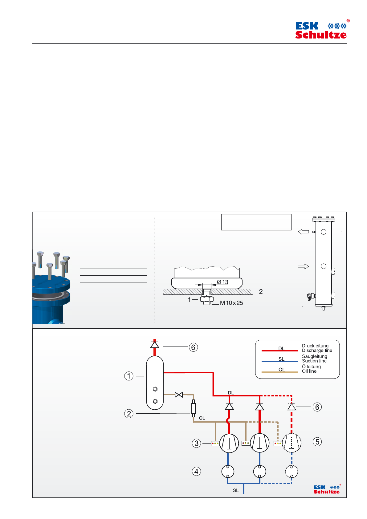
1 Ölabscheider-Sammler BOS2-R
2 Ölfilter
FF-16B / F-16B
3 Ölspiegelregulator ERM5
4 Flüssigkeitsabscheider FA..
5 Verdichter
6 Rückschlagventil
1 Oil separator reservoir BOS2-R
2 Strainer FF-16B / F-16B
3 Oil level regulator ERM5
4 Suction line accumulator FA..
5 Compressor
6 Check valve
Systemdiagramm:
ORS 5 mit Hochdruck-Ölreservoir
Flow diagram:
OCS5 with high pressure
oil reservoir
©
3/4
MADE
IN
GERMANY
www.esk-schultze.de
Anzugsmomente Montagevorschrift Nur vertikal installieren!
für die Schraubverbindungen Mounting instructions Vertical installation only !
Tightening torques
for the screw fixings
1) Anzugsmoment: 25 Nm / Mounting torque: 25 Nm
2) Montageplatte / Mounting plate
Fußbefestigung
Foot mounting:
Typ/ Type BOS2-R-22F
M 10 x25 60 Nm
M 12x50 60 Nm
M 16 x45 90 Nm
Hinweis: Schrauben über Kreuz
und in mindestens zwei Schritten
anziehen.
Notes: Tighten screws crosswise
and at least in two steps.
Montageposition
Mounting position

Sicherheitshinweise
• Alle Komponenten und deren Zubehör sind für die Handhabung, Installa-
tion und den Gebrauch durch fach- und sachkundige Anlagenbauer, Instal-
lateure und Betreiber vorgesehen. Diese müssen über grundlegende Kennt-
nisse der Kältetechnik, der Kältemittel und der Kältemaschinenöle verfügen.
• Unsachgemäße Handhabung oder Missbrauch
können zu Sach- oder Personenschäden führen.
• Die Einhaltung der Einbauvorschriften und Anwendungsgrenzen
(Druck, Temperatur, Medien) sind Voraussetzung für eine sichere Funktion.
• Vor Befüllung der Kälteanlage mit Kältemittel ist eine Dichtigkeitsprüfung
der Anlage, einschließlich der eingebauten ESK-Komponenten durchzu-
führen. Für die Druckprüfung darf kein reiner Sauerstoff verwendet werden.
• Bei der Handhabung von Kältemitteln und Kältemaschinenölen und bei
der Durchführung von Arbeiten am gefüllten Kältekreislauf sind die jeweils
gültigen Unfallverhütungsvorschriften zu beachten.
• Bei der Entsorgung von Altöl bzw. Kältemittel
sind die gesetzlichen Vorschriften einzuhalten.
• Das Öffnen von ESK-Geräten darf nur im
drucklosen und abgekühlten Zustand erfolgen.
Safety instructions
• All components and accessories are for use and installation by compe-
tent experts with fundamental knowledge of refrigeration systems, refrig-
erants and refrigeration oils only.
• Improper use can lead to material damage or personal injury.
• Keeping all instructions (pressure, temperature, media)
creates the condition for a reliable function.
• Before charging the refrigeration system with refrigerants you have to
make sure that the system, including the ESK-components, is tight. Do not
use oxygen for this test.
• While handling refrigerants, refrigeration oils or handling with filled
up refrigeration systems, you have to pay attention to all regulations for
prevention of accidents.
• If you have to dispose refrigerants or refrigeration oils,
make sure to keep all legal regulations.
• ESK products must not be opened while they are
under pressure and until the vessel has cooled down.
Rücksendung von Komponenten
Vor der Rückgabe sind die Geräte vom Rücksender komplett zu entleeren,
das heißt, die Geräte werden ohne Öl und Kältemittel angeliefert.
Return of components
When returning components the devices must be exhausted completely by
the return sender, i.e. the devices are delivered without oil and refrigerants.
MAL_BOS2-R_2019.08-30
Betrieb mit brennbaren Kältemitteln
Es besteht ein erhöhtes Risiko von leichter Entflammbarkeit, toxi-
scher Wirkung und Explosivität. Grundvoraussetzungen für die Herstellung
und den Betrieb derartiger Anlagen sind Kältemittel spezifische Kenntnisse
und die absolute Einhaltung der Sicherheitsvorschriften für Kältemittel. Es
dürfen nur Komponenten eingesetzt werden, die von ESK für solche Anwen-
dungen konstruiert und freigegeben wurden.
Für die Herstellung, den Betrieb und den Service von Kälteanlagen
mitbrennbarenKältemitteln sindbesondereBestimmungengültig.
Es sind Vorkehrungen zu treffen, die bei einem Kältemittelaustritt eine
gefahrlose Entlüftung gewähren, damit kein zündfähiges Gasgemisch
entsteht. In folgenden Normen sind zum Beispiel Bestimmungen über die
Ausführung von Anlagen beschrieben: EN 378, DGUV 100-500 Kap. 2.35
Operation with inflammable refrigerants
There is an increased risk of high inflammability, toxic effects and
explosiveness. Refrigerant-specific knowledge as well as strictly keeping
the safety regulations are fundamental requirements for the production
and operation of such plants.
Only components shall be used that have been constructed and released
by ESK for such installations and/or operations.
For the production, operation and service of refrigeration plants
with inflammable refrigerants, special regulations come into force.
Precautions must be taken so that, upon discharge of refrigerant, a safely
ventilation is guaranteed, in order to avoid the development of an ignit-
able gas mixture.The following norms describe e.g. regulations regarding
the execution of plants: EN 378, DGUV 100-500 ch. 2.35
Betrieb mit dem Kältemittel R 744 /CO2(Kohlendioxid)
ESK fertigt Komponenten für den sub- und transkritischen Betrieb.
Das Kältemittel ist farb- und geruchlos und bei einem Austritt nicht wahr-
nehmbar. Das Einatmen in erhöhter Konzentration kann zu Bewusstlosig-
keit und Ersticken führen. Die Entlüftung der Maschinenräume hat nach
EN378 zu erfolgen.
Die hohe Drucklage von CO2stellt eine Gefahr dar und ist
zu beachten. Bei Anlagen-Stillstand steigt der Druck bei Umge-
bungstemperatur erheblich und es kann Berstgefahr bestehen. Der kriti-
sche Punkt liegt bei 31°C und 74 bar. Absperrbare Anlagenteile sind mit
einem Sicherheitsventil auszurüsten (EN 378-2 und EN 13136).
Es darf kein Rohr am Sicherheitsventil angeschlossen werden, um beim
Öffnen ein Blockieren durch Trockeneisbildung zu vermeiden.
Es können sehr hohe Druckgastemperaturen auftreten, es besteht
Verbrennungsgefahr an Ölabscheider-Oberflächen und an Ölrück-
führ- und Druckausgleichsleitungen.
ESK-Komponenten dürfen nur für die freigegebenen Anwendungsbereiche
eingesetzt werden. Bei Verwendung hochviskoser Kältemaschinenöle
>46 cSt ist die korrekte Funktion der Komponenten während der Inbetrieb-
nahme zu kontrollieren und zu überwachen. Gegebenenfalls sind korrigie-
rende Maßnahmen zu ergreifen.
Operation with refrigerant R 744 / CO2(carbon dioxide)
ESK produces components for sub- and transcritical running.
The refrigerant is colourless and odorless, and is not noticeable upon
discharge. Inhaling elevated concentrations can lead to unconsciousness
and suffocation. Ventilation of the machine rooms must be carried out in
accordance to EN378.
The high pressure condition of CO2is dangerous and must be
observed. In case of stop of the plant, the pressure elevates signifi-
cantly at the ambient temperature and there may be danger of burst. The
critical point is 31°C and 74bar. Parts of the plant that can be blocked must
be prepared with a safety valve (EN378-2 and EN13136.)
To avoid, upon opening, a blocking caused by dry ice accumulation,
it is not allowed to connect a tube to the safety valve.
Very high discharge gas temperatures may develop. There is a risk
of burns at oil separator surfaces and at oil return and pressure
equilazation lines.
ESK components shall only be used within the approved application range.
Whenusing highlyviscosecoolingmachine oils>46 cSt,thecorrect function
of the components must be controlled and monitored during operation.
Where applicable, corrective measures must be taken.
Bitte beachten Sie unsere speziellen Sicherheits-
hinweise zum Einsatz natürlicher Kältemittel!
Please follow our specific safety instructions
for operations with natural refrigerants !
Hochleistungs-Ölabscheider-Sammler
High performance oil separator reservoirs
BOS-R
4/4
www.esk-schultze.de
Änderungen vorbehalten! ▪ Subject to modification!
Direct Contact:
www.esk-schultze.de
ESK Schultze GmbH & Co. KG
Parkallee 8 16727 Velten
GERMANY
+49 (0) 3304 3903 0
+ 49 (0)3304 3903 34
This manual suits for next models
7
Other ESK Water Filtration System manuals


Popular Water Filtration System manuals by other brands


Philips
Philips WP3822 Micro X-Pure Specification sheet

Panasonic
Panasonic ET-EMF330 operating instructions

R-Can
R-Can Sterilight S12Q Installation instructions and owner's manual

Certikin
Certikin SALT EXPERT-3 Series operating instructions

Vega
Vega VEGATRENN 152 operating instructions

Boss Water Systems
Boss Water Systems 021-4P-GM Installation and service guide


