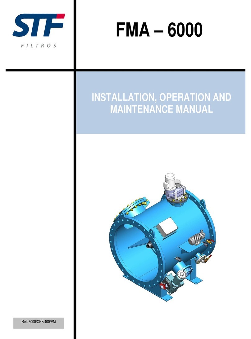
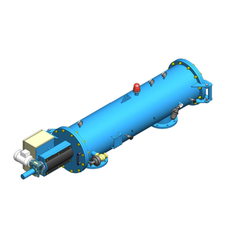
STF-Filtros FMA-3000 User manual

Installation, Operation and Maintenance Manual – FMA 3000
Ref: 3000/T/6/VH 1
FMA – 3000
INSTALLATION, OPERATION AND
MAINTENANCE MANUAL
Ref: 3000/T/6/VH

Installation, Operation and Maintenance Manual – FMA 3000
Ref: 3000/T/6/VH 2
CONTENTS
1. – INTRODUCTION...........................................................................................................................6
2. – WARRANTY..................................................................................................................................7
3. – SAFETY.........................................................................................................................................8
4. – DESCRIPTION OF FILTER FMA-3000....................................................................................10
5. –FMA-3000 OPERATION ............................................................................................................12
6. – TECHNICAL CHARACTERISTICS...........................................................................................13
7. – NAMEPLATE..............................................................................................................................18
8. – INSTALLATION INSTRUCTIONS.............................................................................................19
9. – START-UP INSTRUCTIONS. ...................................................................................................21
10. – MAINTENANCE INSTRUCTIONS .........................................................................................22
11. – PREVENTIVE MAINTENANCE SCHEDULE ........................................................................23
12. – CONTROL PANEL...................................................................................................................24
12.1. – CONNECTION......................................................................................................................26
12.2. – OPERATION.........................................................................................................................27
12.3. –CHANGING SETTINGS .......................................................................................................28
13. – NOTICES AND ALARMS .......................................................................................................32
14. – HYDRAULIC CIRCUIT............................................................................................................33
15. – PARTS......................................................................................................................................35
16. – ERROR DETECTION AND TROUBLESHOOTING...............................................................40

Installation, Operation and Maintenance Manual – FMA 3000
Ref: 3000/T/6/VH 3
This appliance has been designed so that it does not cause any risk during the use for which it
has been designed, provided that:
Both the installation and management and maintenance are carried outin accordance with the
instructions in this manual.
The conditions of the premises and the supply voltagemeet those specified.
Any use other than this will be considered misuse, as will the addition of any modifications not
expressly approved by the manufacturer. Only the user will be fully responsible for injuries or
damages caused by misuse, which will automatically result in any warranty being void.
Remember that this device contains live electrical devices and, therefore, all service or
maintenance operations shall be performed by qualified and experienced personnel, who are
aware of the necessary precautions. Disable power before accessing the internal parts.
READ AND SAVE THESE INSTRUCTIONS
We want to save you time and money!
We assure you that fully reading this manual will guarantee
proper installation and safe use of the product.
IMPORTANT NOTICE
READ AND FOLLOW THE INSTRUCTIONS IN THIS MANUAL BEFORE
INSTALLATION OR ASSISTANCE IN THE DEVICE. THE MANUFACTURER
WILL NOT BE LIABLE FOR ANY DAMAGE THAT MAY RESULT, EVEN
FOR NEGLIGENCE CAUSED BY NOT READING THE MANUAL

Installation, Operation and Maintenance Manual – FMA 3000
Ref: 3000/T/6/VH 4
WARNING!
RISK OF ELECTRIC SHOCK. THE OPERATIONS MARKED WITH THIS
SYMBOL MUST ONLY BE PERFORMED BY QUALIFIED PERSONNEL
WARNING!
ESSENTIAL INFORMATION AND ISSUES.
PLEASE REFER TO THE DOCUMENTATION ACCOMPANYING THE
DEVICE.
NOTE
VERY IMPORTANT INFORMATION AND ISSUES.

Installation, Operation and Maintenance Manual – FMA 3000
Ref: 3000/T/6/VH 5

Installation, Operation and Maintenance Manual – FMA 3000
Ref: 3000/T/6/VH 6
1. – INTRODUCTION
STF - FILTROS congratulates you for purchasing FMA – 3000 self-cleaning screenfilter.
All products manufactured by STF - FILTROS are easy to install, use and maintain.
Should you have any questions about the operation after reading this manual, please contact
STF-Filtros technical department.
CONTACT
SISTEMA DE FILTRADO Y TRATAMIENTO DE FLUIDOS S.A
+34 974 401 933
+34 974 417 809
info@stf.filtros.com
www.stf-filtros.com

Installation, Operation and Maintenance Manual – FMA 3000
Ref: 3000/T/6/VH 7
2. – WARRANTY

Installation, Operation and Maintenance Manual – FMA 3000
Ref: 3000/T/6/VH 8
3. – SAFETY
INSTRUCTIONS FOR THE SAFE USE OF THE FILTER
MISUSE AND IMPROPER MAINTENANCE OF THIS DEVICE CAN CAUSE
INJURY TO USERS.
TO AVOID THESE RISKS, YOU ARE STRONGLY ADVISED TO FOLLOW
THE INSTRUCTIONS BELOW.
TAKE AS MANY ACCIDENT PREVENTION MEASURES AS POSSIBLE TO
ENSURE PERSONAL AND EQUIPMENT SAFETY.
Do not touch moving parts.
Never place your hands, fingers or other body parts near the moving parts of the filter.
Do not use the filter if the guards have not been fitted.
Never use the filter if all guards have not been fitted perfectly into place (eg protective casing). If
maintenance operations require removing them, make sure the guards are securely fastened
back in their proper places before using the filter again.
Protect yourself against electric shock.
Prevent accidental contact of electrical parts of the device with metal parts thereof.
Disconnect the filter.
Disconnect the device from the power source before performing any assistance, inspection,
maintenance, cleaning, replacement or part control operations.
Release filter pressure.
Pressure off the device prior to any assistance, inspection, maintenance, cleaning, replacement
or part control operations.
Work area.
Keep work area clean and put away any potential unnecessary tools. The device can produce
sparks during operation, do not use the device in situations where varnishes, gasoline or other
combustible or explosive materials can be found.
Maintenance of the filter.
Follow the instructions in this manual, check greasing, inspect the power cable periodically and if
damaged have it repaired by qualified personnel. Check that the external appearance does not
show any visual abnormalities.

Installation, Operation and Maintenance Manual – FMA 3000
Ref: 3000/T/6/VH 9
Check that screws, bolts and the cover are firmly fastened.
Regularly check they are tight.
Operate the device at nominal voltage.
Bear in mind the voltage specified in this manual and on the filter nameplate.
Never use the filter if it is defective.
If the filter makes strange noises, produces excessive vibration or appears defective, stop
operation immediately and check its functionality.
Use genuine spare parts only.
The use of non-genuine spare parts voids the warranty.
Do not modify the filter.
An unauthorized modification can decrease the performance of the device and cause serious
accidents to people who do not have adequate technical knowledge.
Disconnect and drain the device.
When the filter is not working, disconnect the device from the power and drain the filter to extend
the life of the product.

Installation, Operation and Maintenance Manual – FMA 3000
Ref: 3000/T/6/VH 10
4. – DESCRIPTION OF FILTER FMA-3000
The filter consists of an outer casing which houses three distinct chambers. The first one is a
prefiltering chamber which coincides with the filter water inlet, and where the Coarse Mesh is
located, the second one is a FILTERING CHAMBER where the fine mesh is located and where
the filtering process takes place and the third one, which is acleaning chamber.
In this case the water flows outwards from inside the filtering body. Suspended solids (dirt) are
retained in the filtering element, ie in the mesh. This chamber coincides with the filtered water
outlet to the desired application: drinking water, process water, cooling water, etc.
The dirt retained gradually forms a cake on the mesh, which generates a given pressure drop.
Cleaning the filter is supported by a second chamber, the CLEANING chamber, whose outlet is
connected to the DRAIN VALVE allowing evacuation of the wash water when generating the
SELF-CLEANING process. The cleaning chamber is separated from the filtration chamber by
means of a special seal.
Finally, the SUCTION SCANNER is a vital element of this technology. This scanner occupies the
exact position that the central axis of the filtering cartridge would occupy, and is hydraulically
connected to the cleaning chamber. In turn, the SUCTION NOZZLES are arranged
perpendicularly in the zone that itoccupies in the filtration chamber, with the nylon bristles
2
45
9
1
–
Water inlet.
2 – Water outlet.
3 – Roughing chamber.
3 – Filtering chamber.
5 – Cleaning chamber.
6 – Roughing cartridge.
7 – Filtering cartridge.
8 – Scanner set.
9
–
Actuation mechanism.
1
3
678

Installation, Operation and Maintenance Manual – FMA 3000
Ref: 3000/T/6/VH 11
reaching a few microns away from the mesh. The location of these nozzles in the suction scanner
has been designed to come into contact with the entire inner surface of the mesh, thanks to the
spiral movement provided to the scanner by the electric motor by combining longitudinal
displacement and rotation.

Installation, Operation and Maintenance Manual – FMA 3000
Ref: 3000/T/6/VH 12
5. –FMA-3000 OPERATION
Water enters the filter through the roughing chamber, which works like a stone trap
where any coarse particles are retained.
The water flows outwards through the FINE MESH, thus producing SURFACE
MECHANICAL FILTRATION. High quality water is then obtained according to the degree
of filtration chosen for the filter mesh, which can vary from100 to 2,000 microns.
Dirt is retained and accumulated on the inner surface of the fine mesh, while causing a
gradual pressure drop between inlet and outlet of the filter. A differential pressure switch
will trigger the washing sequence when a DP equal to 0.3 bar (3 m.c.a.) is reached.
There are other possibilities to carry out the filter wash, namely wash by time, and
manual wash option.
When the differential pressure switch indicates 0.3 bar, the drain valve is commanded to
open, thus generating a differential pressure between the outside (atmospheric pressure)
and the inside of the filter (work pressure) so that a current of water at high speed is
produced, which goes through the mesh and is led to the outside through the inner hole
of the nozzles. The rotational motion is generated by this same flow passing through the
hydraulic motor located inside the cleaning chamber, while the longitudinal motion is
generated by the hydraulic piston located at the top of the filter.
The result of these joint actions is the suction effect of the nozzles onto the dirt on the
mesh, and the spiral movementof the suction scanner inside the filter.
During the self-cleaning process, which lasts 20 seconds, water continues to be filtered
and flowing into the system or application. This is due to the design of these filters, which
allows the consumption of water for washing to be MINIMAL and the duty cycle to be
CONTINUOUS.

Installation, Operation and Maintenance Manual – FMA 3000
Ref: 3000/T/6/VH 13
6. – TECHNICAL CHARACTERISTICS
Flow rates are calculated for a filtration rate of 125 microns, please consult about others.

Installation, Operation and Maintenance Manual – FMA 3000
Ref: 3000/T/6/VH 14
MODEL 3003 3004 3006 3008 3010
GENERAL FEATURES
Diameter Inlet/Outlet (1) DN-80 (3”) DN-100 (4”) DN-150 (6”) DN-200 (8”) DN-250 (10”)
Max./mín. working pressure 2 bar / 10 bar (please consult about others)
Max. fluid temperature 50 ºC
PVC MESH SUPPORT
Maximum flow rate (m3/h) 110 180 250 400 550
Gross filteringarea (cm2) 2,450 4,800 7,200 9,600 12,000
Net filtering area (cm2) 1,600 3,200 4,800 6,400 8,000
Dry weight (kg) 60 75 90 131 164
Filtration sizes 1,000, 500, 300, 200, 125,100 microns
STAINLESS STEEL MESH
SUPPORT
Maximum flow rate (m3/h) 110 180 250 400 550
Gross filteringarea (cm2) 2,450 4,800 7,200 9,600 12,000
Net filtering area (cm2) 1,600 3,200 4,800 6,400 8,000
Dry weight (kg) 62 80 98 142 179
Filtration sizes 1,000, 500, 300, 200, 125, 100microns
BACKWASH
Backwash valve G-2” Thread
Duration of wash cycle 20-40 seconds
Wash flow (m3/h) 3 6.5 14 23 28
Water consumption per wash
(liters) 25 49 110 178 238
ELECTRICAL DATA
Operating voltage 4 x 1.5 VLR 14-Cbatteries/ (optional 220 V AC 50Hz)
Control voltage 6 V DC / (24 V DC optional 220 V AC)

Installation, Operation and Maintenance Manual – FMA 3000
Ref: 3000/T/6/VH 15
STANDARDMATERIALS
Filterbody andcaps S-235-JR Carbon steel
Finish treatment Oven-cured epoxy polyester powder paint coating
Suction scanner AISI-304 Stainless steel
Filteringmesh AISI-316 Stainless steel
Suction nozzle PVC with AIS 316stainlesssteel ring andnylon bristles
Cleaning valves Polypropylene
Screws A2 Stainlesssteel
Gaskets NBR – EPDM - Viton
SPECIAL MATERIALS (OPTIONAL)
Filterbody andcaps A-516 Carbon steel / AISI 304 /AISI 316/ SuperDuplex Stainless steel
Finish treatment Inner coating suitable for sea water, outer coating suitable formarine
environment.
Suction scanner Duplex orSuperduplex Stainless steel
Filteringmesh 254 SMO Avesta Stainless steel
Suction nozzle Complete, made of Duplex or Superduplex Stainless steel and nylon
bristles
Cleaning valves “Please consult about optional materials”
Screws A4 Stainlesssteel
Gaskets Please consult

Installation, Operation and Maintenance Manual – FMA 3000
Ref: 3000/T/6/VH 16
STANDARDMATERIALS
Filterbody andcaps S-235-JR Carbon steel
Finish treatment Oven-cured epoxy polyester powder paint coating
Suction scanner AISI-304 Stainless steel
Filteringmesh AISI-316 Stainless steel
Suction nozzle PVC with AIS 316stainlesssteel ring andnylon bristles
Cleaning valves Polypropylene
Spacer disc Aluminium
Screws A2 Stainlesssteel
Gaskets NBR – EPDM - Viton
SPECIAL MATERIALS (OPTIONAL)
Filterbody andcaps A-516 Carbon steel / AISI 304 /AISI 316/ SuperDuplex Stainless steel
Finish treatment Inner coating suitable for sea water, outer coating suitable formarine
environment.
Suction scanner Duplex orSuperduplex Stainless steel
Filteringmesh 254 SMO Avesta Stainless steel
Suction nozzle Complete, made of Duplex or Superduplex Stainless steel and nylon
bristles
Cleaning valves “Please consult about optional materials”
Spacer disc A2 or A4 Stainless steel
Screws A4 Stainlesssteel
Gaskets Please consult

Installation, Operation and Maintenance Manual – FMA 3000
Ref: 3000/T/6/VH 17

Installation, Operation and Maintenance Manual – FMA 3000
Ref: 3000/T/6/VH 18
7. – NAMEPLATE
All devices are identified by means of a nameplate pasted on the filter.
It includes the following data:
Device series.
Model.
Serial number of the device in question.
EC Certificate

Installation, Operation and Maintenance Manual – FMA 3000
Ref: 3000/T/6/VH 19
8. – INSTALLATION INSTRUCTIONS
Take any necessary precautions to prevent bumping the filter. Lift the device by using the
anchoring points at the top.
Make sure the installation point has the minimum operating pressure.
oThe discharge pipe should be dimensioned to generate a minimum pressure loss
at a flow rate of 30 m³/h.
oIn facilities with a working pressure above 6 bar, we recommend installing a ball
valve on the discharge pipe in order to adjust the washing flow.
NOTE
MINIMUM OPERATING PRESSURE IS 2 BAR BETWEEN FILTER OUTPUT
AND DRAIN VALVE.
IN THE EVENT THAT THE DRAINAGE IS REDIRECTED, THERE MAY BE
BACKPRESSURE DUE TO PRESSURE DROP AND INCREASES IN
HEIGHT.
Install filter vertically, make sure to leave enough space to allow easy access to your
device for future treatments and to perform maintenancesafely. See section 6.
Orient the filter in the pipe according to the arrows indicating water flow direction.
It is recommended to install shutoff valves at the inlet and outlet of the filter to allow
insulation from the pipe. To avoid outages during maintenance, it is recommended to
install a bypass.
We recommend installing an anti-backflow valve at the outlet to prevent water hammer in
the filter.
The electrical wiring can only be carried out by a licensed electrician in accordance with
section 12.1
When installing the filter, prevent water from splashing onto the electrical components or
the control panel.

Installation, Operation and Maintenance Manual – FMA 3000
Ref: 3000/T/6/VH 20
RANGE OF PRESSURES
Kg/cm2 2 3 4 5 6 7 8 9 10
TIME 45 seconds 30 seconds 25 seconds 20 seconds
Diferential pressure installation ( pressure switch )
The differential pressure sensor is equipped with two maneuver tubes which must be
connected to the filter. The red tube shall be connected to the high pressure area (filter inlet)
and the black tube shall be connected to the low pressure area (filter outlet). It is advisable to
install a small 120 mesh filter before the high pressure inlet to the pressure switch.
CLEANING TIME
DEPENDING ON WORKING PRESSURE, YOU MUST SET A CLEANING
TIME ON THE PROGRAMMING UNIT (SEE ATTACHED CHART).
Table of contents
Other STF-Filtros Water Filtration System manuals
Popular Water Filtration System manuals by other brands
Filtration Group
Filtration Group Pi 480 installation instructions

Sharp
Sharp FZ-6400MF Operation manual

Circutor
Circutor AFQm IP54 instruction manual

Exo Terra
Exo Terra Monsoon SOLO II operating instructions

BWT
BWT PERMAQ COMPACT 41 Installation and operating manual

Oase
Oase BioSmart 5000 operating instructions