AOW-3000-R_20190405
IMPORTANT — Be sure red tube
and elbow are completely inserted.
1Turn off cold water valve under the sink. Release the
pressure from the system by turning on the ltration
system faucet. Once there is no water coming from the
ltration system faucet, you will be ready to change
the lters.
2Disconnect the 1/4" red hose from
the drain port on the membrane lter
elbow by pushing down on the collar
while pulling the plug with your other hand.
3 Remove the membrane cartridge
from the system by rotating the
sump to the left and pulling
down.
4Discard the old membrane cartridge.
5Take the new membrane cartridge from the
packaging and remove the protective cap from
the head of the membrane.
6Attach membrane cartridge to the bottom of the
top housing rst, making sure all connection points
are aligned. Push the top of the sump up and into the
bottom of the top housing and turn the sump towards
the right. Ensure the sump is fully attached and locked.
7Insert the new ow restrictor
into the red 1/4" tubing. Push
red tubing into the drain port elbow
on membrane lter.
8Turn on the cold water valve.
Purge the system by turning on
the RO faucet and letting water ow
through the system for 24 hours
9Once the system has been purged, turn off the
RO faucet. Allow 2 hours for pressure to build up
in the system and check for leaks. Your RO
system is ready to use.
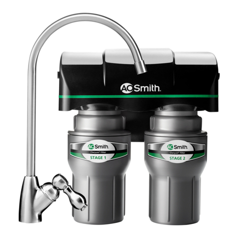
1Turn off the cold water valve under the sink.
Release the pressure from the system by
turning on the ltration system faucet.
When no water ows from the ltration
system faucet, you will be ready to
change the lters.
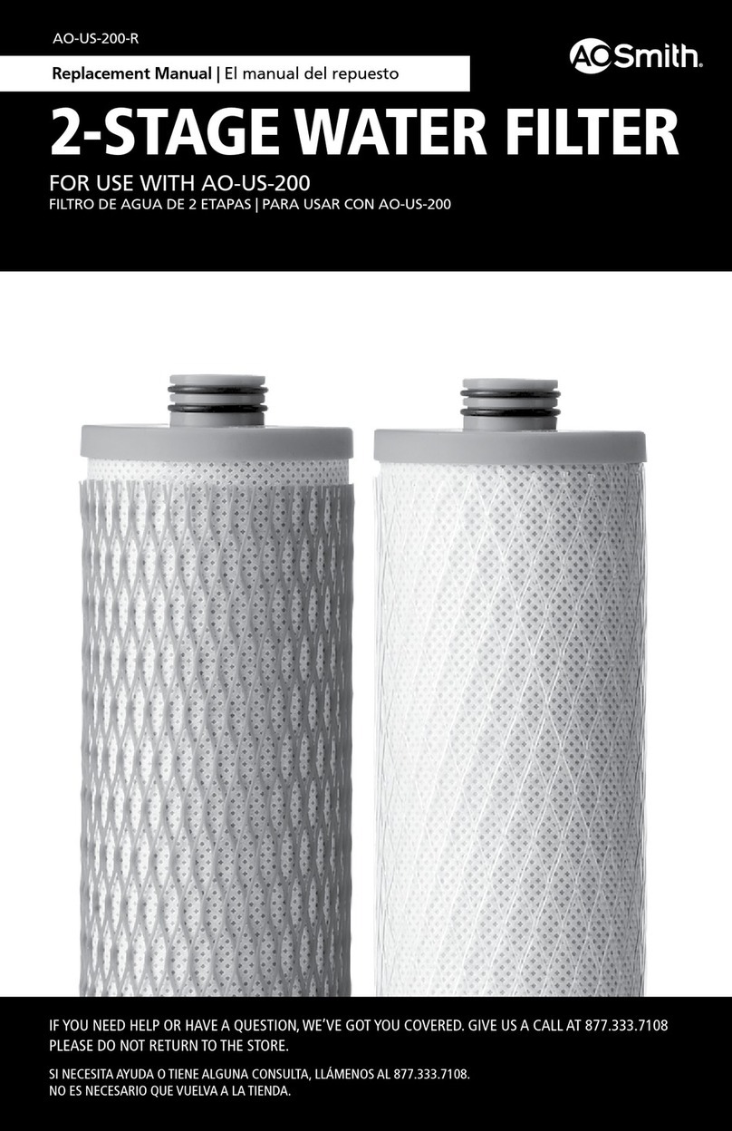
2Remove plastic wrap from replacement lter cartridges.
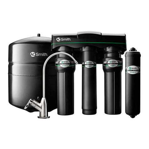
3 Remove Stage 1 & Stage 3 sumps
from the ltration system by rotating
the sump to the left and pulling down.
4Hold each cartridge sump over the sink.
Separate the two pieces of the sump by
turning the bottom portion of the sump
to the left. Pour excess water down the drain.
Pull down on each cartridge to disconnect the
lter cartridge from the top half of the sump.
5 Insert and connect each new lter
cartridge to the top half of the sump.
Reattach the bottom of sump to the top
half by turning to the right and tightening
Insert the cartridge with clear netting into
Stage 1 sump. Insert the cartridge with
blue netting into Stage 3 sump.
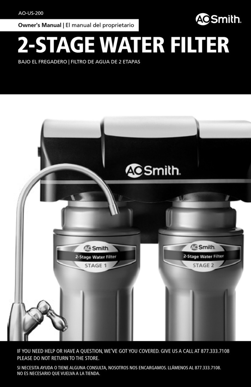
6Reattach each sump to the top housing. Ensure all
connection points are aligned. Push the top of the sump
up into the bottom of the top housing
and turn the sump to the right. Ensure
the sump is fully attached and locked
into Stage 1 on the left and Stage 3
on the right.
7Once both lter cartridges have been changed and sumps
are securely attached to the top housing, slowly turn on
the cold water valve. Conrm the ltration system faucet is
turned off and allow the tank to completely ll (this may
take around two hours).
8Once the tank has completely lled, inspect for leaks.
9If there are no leaks, ush the lter cartridges by
turning on the ltration system faucet and allowing the
water to run through the lters until there is no more
pressure coming out of the faucet.
10 Turn off the ltration system faucet and allow two hours
for the pressure to build in the system. Your ltration
system is ready for use.
Use of parts from other manufacturers may result in loss of contaminant reduction
performance, system damage or failure. Use of parts from other manufacturers will
also void your warranty. A. O. Smith is not liable for consequential or incidental
damages due to improper installation. Warranty information can be found at
aosmith.com/wholesale ©2019 A. O. Smith
A. O. Smith Corporation | P.O. Box 1597
Johnson City, TN 37605-1597 | 833.232.9711
1
3
2
For use with municipally treated water only. Do not use with water
that is microbiologically unsafe or of unknown water quality
without adequate disinfection before or after the system.
The AOW-3000 Pre-Filter has been Tested and Certied by
NSF International in model AOW-3000 against NSF/ANSI
Standard 42 for material safety only.
The AOW-3000 Post-Filter has been Tested and Certied by
NSF International against NSF/ANSI Standards 42, 53, 401
and conforms to NSF Protocol P473 in model AOS-3000 for
the reduction of the claims specied on the Performance
Data Sheet and at www.nsf.org.
REPLACEMENT
ELEMENT
TIP: Have a towel to catch any water that drips.
1
3
2
Do not use tools other than the undercounter wrench
to remove or tighten sumps. Over-tightening can
cause damage and result in leaking.
NOTE: If using the undercounter wrench provided
with the original system, follow these steps.
1 2
3 4
1
2
1
2
22
1
1
• Conforms to NSF/ANSI Standards 42, 53, 401 and conforms to
NSF Protocol P473 for the specic performance claims as
veried and substantiated by test data. See performance data
sheet for individual contaminants and reduction performance.
• Rated capacity: 365 gallons (1,382 liters).
• Systems certied for cyst reduction may be used on disinfected
waters that may contain lterable cysts.
• Conforms to NSF/ANSI Standard 58 for substances listed on the
performance data sheet. See performance data sheet for individual
contaminants and reduction performance: www.nsf.org.
• Rated capacity: 12-24 months depending on contaminant
levels & usage.
• Systems certied for cyst reduction may be used on disinfected
waters that may contain lterable cysts.
For use withmunicipallytreated water only. Donot use with water
that is microbiologically unsafe or of unknown water quality
without adequate disinfection before or after the system.
Tested and Certied by NSF International against NSF/ANSI
Standard 58 in model AOW-3000 for the reduction of the items
specied on the Performance Data Sheet and at www.nsf.org
REPLACEMENT
ELEMENT
1
2
2
1
INSTRUCTIONS FOR AOW-3000 MEMBRANE REPLACEMENT:
NEED HELP? GIVEUS A CALL 877.232.9711 For more information, please visit our website at aosmith.com/wholesale.
INSTRUCTIONS FOR AOW-3000 CARBON BLOCK REPLACEMENTS:
