ESP Safety UPES-50D User manual

UPES-50D
Digital RS485 Multi-Channel Controller
Operating Manual

2
TABLE OF CONTENTS
Description of UPES Controller……………………………………………………..2
Basic Specifications………………………………………………………………….4
UPES Device………………………………………………………………………...5
Pre-Starting Procedure………………………………………………………………7
Operating Procedure………………………………………………………………...8
UPES Display Information for Gas Detectors……………………………………...10
UPES Display Information for Flame Detectors…………………………………...11
Front Panel LED Indicators………………………………………………………...12
Operating Mode Alarms of the Power Supply……………………………………...13
UPES Installation Clearance Consideration………………………………………...14
System Functionality………………………………………………………………..14
Device Search Options……………………………………………………………...15
Possible Malfunctions and Corrections……………………………………………..16
Description of the UPES Programming Tree Diagrams…………………………….18
UPES Menu in the Absence of the channel boards…………………………18
UPES Menu with the Channel Boards Installed…………………………….21
UPES Channel Programming ………………………………………… …...22
UPES Channel Board Com-Ports Operation Mode Setting ………………...25
UPES Channel Copy Settings……………………………………………….26
UPES Sensor Search………………………………………………………...27
UPES Sensor Search by Address…………………………………………....29
UPES Sensor Search by Type of Sensors…………………………………....31
UPES Sensor Search by List of Sensors……………………………………..33
UPES Sensor Search by All Types (Automatic)……………………………..35
UPES and PC Exchange Protocol……………………………………………………36
Power Cable Connection Diagram…………………………………………………...48
Wiring Diagrams for Flame Detectors Connections..………………………………..48
Wiring Diagrams for Gas Detectors Connection……………………………………..49
UPES Markings……………………………………………………………………….49
Transportation and Storage…………………………………………………………...50
Preventive Maintenance………………………………………………………………50
Warranty………………………………………………………………………………51

3
Description of UPES Controller
UPES-50D (hereinafter –UPES) is designed to operate with primary detectors via Modbus
RS485 signals. The input signal exceedance of the set threshold levels is controlled by audible
and LED alarms as well as connected peripheral devices via relay outputs for RS-485 interface
transmission of all channel data in Modbus RTU protocol format.
UPES is installed outside the explosion hazard zones and shall be operated at temperatures from
- 10 to 50 °C and relative ambient air humidity up to 95% at 35°С. UPES functional capabilities
enable to power up to 16 primary detectors: SGOES, TGAES Rx, TGAES Tx, SSS-903, IPES
IR/UV, IPES IR3.
The UPES multi-channel controller consists of a control panel capable of connecting up to 16X8
devices via RS485. From 1 to 128 devices can be connected to the UPES50D controller using
Modbus RS485. The UPES controller can only provide power supply to no more than 16
primary detectors by itself at 24VDC each. If more than one device is to be connected to each
channel card, an additional power supply will be necessary. The UPES can only power one
device per channel. Each Channel of the UPES has 2 dry contact relays for the first alarm
threshold and for the second alarm threshold. There is also a common dry contact relay for the
third alarm threshold for all channels. All dry contacts relays provide current switch up to 2A at
220VAC.

4
Basic Specifications
Table 1. Basic Specifications
Relative humidity at temperature 35 C, %
up to 95
Ambient temperature range
from -10 up to +50 C
Input voltage range with various power
supply units
power supply
unit of BP-1
design
187-242 V 50 Hz (main power) or
direct current with voltage
18-32 V (backup power)
power supply
unit of BP-10
design
130-242 V 50 Hz (main power) or
direct current with voltage
180-340 V (backup power)
UPES power from DC power supply with
voltage not more than, V
24
UPES commutated current at AC voltage 220
V, А
up to 3
Length, mm
266
Width, mm
482
Height, mm
132
Weight, kg, not more than
17
Ingress protection
IP54
Fig. 1. UPES dimensions
Front panel
Direction of module replacement
Module handles
Modules
Terminal blocks for
cable connection
UPES control panel is designed as a standard
3U19”- type unit to be mounted in a rack

5
UPES Device
Fig.2. UPES Device
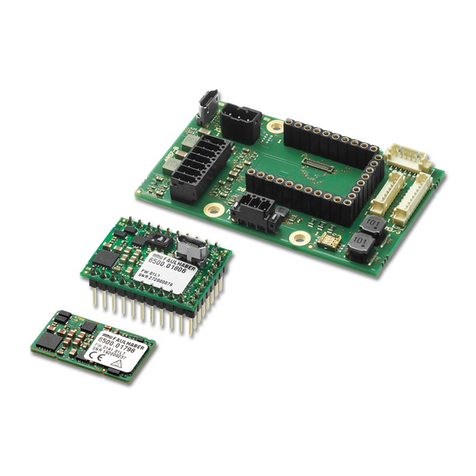
1. CPU board
2. 8 channel boards with 2 communications lines RS485
3. Power supply unit
Fig.2.1. Front View
1. Interconnection board
2. Blind panel
2
3
1
2
1

6
Fig. 2.2. UPES Rear View
1. 2-channel board
2. Processor board
3. Power supply unit
4. Main power socket, 220V input voltage
5. Backup power socket, 220V input voltage.
6. Fault relay
7. Third threshold relay
8. Ground terminal
Fig.2.3. Interconnection Board
1. UPES ON/OFF button
2. LED display
3. Buzzer
4. Keyboard
Each channel of the threshold device has a corresponding LED group:
2 green –Activating +24V at the output of the module;
4 red –exceeding specified thresholds;
2 blue-status indication of the RS-485 bus lines;
2 yellow –indication of sensor malfunction.
Moreover, in case of concentrations of any threshold of any channel are exceeded, an
audible alarm, which is built in UPES, is activated.
5
4
6
7
8
1
3
2
2
1
3
4

7
Pre-starting Procedure
Prior to installation it is necessary to perform visual inspection. Pay attention to the following:
1) signs of damages;
2) availability of all fixture elements;
3) Availability of grounding devices.
Installation shall be performed in accordance with a duly established project of onsite allocation
pursuant to the installation diagram with due account for threshold device design. When
performing installation, consider the following:
1) Local Electrical Installation Regulations
2) Local Safety Regulations on Consumer Electrical Installation Operation;
4) This Operating Manual.
In order to connect UPES to a personal computer via RS-485 communication channel, it is
possible to use any shielded twisted pair cables. In this case, signal wires are connected to
contacts “485А” and “485В”, and the shield is connected to contact “GND”, located at the
terminal block on the controller module rear side. In order to connect UPES to the network and
external actuation and signaling devices, it is possible to use any cables, cords or wires rated for
operational voltage and current specified in this OM.
UPES shall be grounded by means of a screw clamp located at the bottom of the power unit rear
wall. Upon completion of installation, check the following: - insulation resistance, which shall be
not less than 0.5 MOhm; - grounding device resistance, which shall be not less than 4Ohm.
When installing UPES, provide free space above and under it in a rack with height not less than
the threshold device height (132 mm)

8
Operating Procedure
Each of the eight channel modules can communicate with sensors by two RS-485 lines with
MODBUS addresses from 1 to 16, and transmit information to the central processor unit (CPU)
on the concentration and the state of each of the sensors.
The sensors are connected to the module via two separate lines or in a "ring" in accordance with
the requirements of the project. The module supports connection of up to eight sensors on each
RS-485 line and provides power supply for one sensor for each channel. When you connect to
UPES more than 16 sensors, they must be fed from a separate power supply of + 24V.
One port —communication with sensors via an independent port, 16 sensors
(MODBUS address from 1 to 16) can be connected to the port. The state of the
sensors connected to the port is displayed on the first relay set;
Hot swap —communication with the sensors through the first port. In case of
failure of the first port communication is transferred to the second port (MODBUS
address from 1 to 16). When you activate the first port the communication is
restored in the initial mode;
Ring —communication with sensors via the first port, where the ring integrity is
controlled. When the ring is open, communication between the primary transducers
is performed via two ports (MODBUS address from 1 to 16);
Two independent ports —communication with the sensors via two independent
ports, 8 sensors can be connected to each port. The state of the sensors connected to
the first port is displayed on the first relay set and the state of the sensors connected
to the second port —on the second relay set. The first MODBUS port: 1-8, the
second MODBUS port: 9-16.
The module has two relays on the output with "dry" contacts (relay of first and second threshold)
for each channel.
The boards generate the signals for L3 threshold and Fault relay that are common for all UPES,
the "Fault" LEDs lit up individually for each board of the connected primary transducers of the
RS-485 lines , in case of the sensor failure. Two-channel boards have LED status indication of
the RS-485 lines and continue their work in the absence or failure of the CPU. The channel
module at first-time start-up receives from the CPU the internal number, in accordance with the
location in the UPES enclosure.
For each primary detector the user assigns the MODBUS addresses which are connected to odd
(1-8) and to even (9-16) channels. The CPU remembers the numbers of the boards and the
MODBUS addresses of the sensors connected to each port and when the power is turned off or
lost (failed) recovers the device configuration. To search for sensors and system initialization
assign MODBUS addresses to the sensors from 1 to 16 for each channel board.
The CPU controls the entire block, display, transfers the RS-485 information to the "top level"
on concentration and the state of each of the sensors connected to each channel board. CPU is
controlled with the keyboard, located on the front panel, as well as using the command and
address registers from your PC.

9
When you enable the UPES the "test mode" starts, in which the front panel LEDs start flashing
alternately.
After pressing the "Control" button or in 30 seconds channel modules begin checking the RS-485
lines and consecutive scanning of sensors in accordance with the set MODBUS addresses.
When it detects information about gas concentration exceeding the threshold, the priority
scanning of this sensor is performed and the information is displayed on it, it immediately turns
on threshold LEDs and the threshold relay with the set delay.
NOTE:
It is NOT possible to connect on single-sensor-board gas detectors and flame detectors,
including working on different channels of one card in mode 2 port.
Work algorithm:
1) Connect the device 1 IPES - fire detection trigger two alarm thresholds. Lights up on the
display «Fire»
2) connect the 2 devices and more IPES -
• If a fire one device triggered 1 alarm threshold settings and displayed on the display the
inscription «Attention»;
• When processing with two or more triggers 1 and 2 the alarm threshold, the display you-usual
inscription «Fire»

10
UPES Display Information for Gas Detectors
The display shows the following information: gas detector
1 2 3 4 5 for SGOES
C
h
a
n
1
-
1
0
о
1
5
1
0
0
.
0
0
L
E
L
↑
↑
P
R
O
6 7 9 8
1 2 3 4 5
For TGAES Rx (receiver)
C
h
a
n
1
-
7
о
7
0
L
E
М
С
Н
4
6 7 8
For TGAES Tx (transmitter)
____________________________________________________________________________
1-channel;
2-serial number of the channel board
3- serial number of the sensor connected to the channel board
4 - operating mode of the channel board o- "ring", - " hot swap", -"two
independent channels", - "one channel".
5 - MODBUS address of controlled sensor;
6-gas concentration;
7-measurement units;
8- measured gas type;
9–actuation alarm of one (↑) or two thresholds (↑↑).
C
h
a
n
1
-
8
о
8
S
o
u
r
s
e
T
G
A

11
UPES Display Information for Flame Detectors
The display shows the following information: flame detector
1 2 3 4 5
C
h
a
n
1
-
7
о
7
n
o
r
m
a
F
R
E
6 7
C
h
a
n
1
-
7
о
7
F
i
r
e
F
R
E
C
h
a
n
1
-
7
о
7
F
a
u
l
t
F
R
E
1-channel;
2-serial number of the channel board
3- serial number of the sensor connected to the channel board
4 - operating mode of the channel board o- "ring", - " hot swap", -"two
independent channels", - "one channel".
5- MODBUS address of controlled sensor;
6- mode;
7 –Flame detector

12
Front Panel LED Indicators
The front panel contains LEDs of each of the eight channel modules:
1 - green LEDs indicating turning on of + 24V at the output of the channel
2 - red LEDs indicating the 1-st threshold
3 - red LEDs indicating the 2-st threshold
4- blue LEDs indicating the RS-485 bus lines state
5- yellow LEDs indicating the sensor faults
RS-485 bus line state indication LEDs are turned on at the time of receipt of request from the
channel board to the sensor and are turned off at the time of the receipt of the correct answer
from the requested sensors or upon the expiry of the set time of waiting for a response from the
sensor.
Light up of one of the "Fault" LEDs indicates a failure of one of the sensors in the bus line, or
the absence of response from one of them within the prescribed period of time.
At the back of the UPES there are screw terminal connectors to connect the bus lines from
sensors and cables from the external actuation devices (fans, valves, buzzers, etc.). There are also
mount hole for connecting the network and backup power supply and link with PC through RS-
485 communication channels.
Structurally, the UPES is a unified frame in size of 3U × 19 " (482 × 266 × 132 mm) built in
accordance with the bus structured and modular approach. In the frame there is a power supply
module, CPU module and up to eight two-channel modules. The power supply provides a relay
switch of main supply to 24 VDC reserve power supply.
In the power supply the primary main power supply takes precedence over the primary reserve
power supply for the detector. In the absence of ≈ 220V 50 Hz or in case of the failure of the
primary main power supply, the power supply unit ensures smooth transition to the reserve
supply, generating a sound signal and light indication on the UPES front panel (built-in red and
green LEDs in the UPES power buttons).
UPES is switched ON by continuous (2 sec) pressing on the power button on the front panel of
the device after the feeding of the primary and reserve power supply.
The power supply unit controls voltage outputs of primary power supply transducers and ply and
current consumption from them, compliance with the predetermined voltage limits of all the
reserve power supplies. Overrun of predetermined parameters is signaled by red light indication
on the UPES front panel, as well as sound signals with a simultaneous 24 V supply voltage
dump.
The power supply monitoring system has a separate secondary power source and a 5 V back-up
source with estimated operating time up to 30 seconds.

13
Flashing LEDs illuminating buttons in any color with a frequency of 1 Hz indicates that the
power supply is switched off.
Flashing red button illumination with a frequency of 1 Hz indicates that the power supply
is switched off due to fault in the power supply or overloading of secondary power
sources.
Flashing LEDs illumination button (yellow) with a frequency of 1 Hz indicates that the
power supply is turned off, but one of the input voltage (backup or primary) is absent.
Continuous illumination of LED buttons (any color) indicates that the power supply is
turned on.
Continuous illumination of LED button (yellow) indicates that the power supply is turned
on, but one of the input voltage (back-up or primary) is absent, when the power supply
switches from the back-up source short signals with a frequency of 1 Hz are generated.
Continuous illumination of LED buttons (green) indicates that the power supply is turned
on and all input voltages are connected (back-up or primary).
In all modes, connection or disconnection of any input voltage is indicated by the single sound
signal for 1 second.
Operating Mode Alarms of the Power Supply
Indication Mode
UPES Power Supply
Intermittent green illumination of the
UPES power button
UPES is not turned on, all input
voltages are connected
Intermittent yellow illumination of the
UPES power button
UPES is not turned on
One of the 220V input voltages is
absent
Steady green illumination of the UPES
power button
UPES is turned on.
Supply voltage, the primary and back-
up are connected and normal.
Output voltage of primary
transducers-OK.
Output voltage of secondary
transducers-OK.
Steady yellow illumination of the UPES
power button
Generation of short signals once a
second
UPES is turned on.
Powered by redundant power supply
220V.
Steady yellow illumination of the UPES
power button
There are no sound signals
UPES is turned on.
Powered from the main source
220V
The main and back-up supply in UPES has no commutation through switches, so the power
supply shall be connected to UPES through an external switching device.
The gas analyzer can also be connected with external devices with the cable for the industrial
interface RS-485, RS-422 (4 twisted pairs) cable with armor in the form of corrugated steel can
be used in hazardous areas.

14
To connect the UPES to the PC via the RS-485 communication the shielded twisted pair can be
used.
The external grounding conductor shall be thoroughly cleaned, and its connection with the
external grounding clamp shall be protected from corrosion by applying lubrication grease.
The control panel shall be grounded with a screw clamp located at the bottom of the back wall of
the power supply unit.
At the end of the installation it is required to check:
-insulation resistance, that shall not be less than 0.5 MOhm;
-resistance of the earthing device, that shall not be more than 4 Ohm.
UPES Installation Clearance Consideration
When installing the control panel in a rack there shall be empty space above it and below it that
shall be at least the height of the control panel (132 mm).
System Functionality
Connect the UPES to the detectors and verify its functionality.
For this purpose it is required to release two screws at the top of the front panel of the device,
unscrew the front panel and press ON.
After switching ON the UPES, the central board processor determines whether channel cards are
available. The ("Initializing channels") appears on the display (Fig. 1).
Figure 1. Cyclogram of the messages displayed on the display when UPES is initialized

15
When the search for the channel boards is complete, the test program is initiated. The ("Autotest
Elektronstandart-Pribor") message is displayed on the display in the top row as a crawl line, and
in the bottom line the software version and year of manufacture is displayed. LEDs of the
channel cards initialized flash on alternately. In 30 seconds testing stops. Autotest can be
interrupted by pressing the ("Test") button.
Search Options
If the central board has not found any channel card, the (“Error! No Channel card”) message
appears on the display.
The central board controller transmits the search command to the channel boards sensors
connected. The central board controller alternately scans the search condition of each channel
card. If the UPES autotest has been interrupted by pressing the ("Test") button, the channel
boards expect sensor initialization for 20 seconds, and in this case the indicator in the bottom line
displays the (“Sensors Warm-up”), and in the top line the number of the channel card connected
is changed alternately. After the channel card has completed waiting for warm-up, the sensor
search program starts. If in the channel card memory the MODBUS addresses and sensor types
have been recorded, the channel card controller searches for sensors per this list, otherwise the
search is performed by screening all sensor types in the MODBUS addresses from 1 to 16. The
status of the search for each channel card is displayed alternately on the display. The top line
displays the channel number and the search percentage completion, and in the bottom line
displays the search mode:
(“Search”) search all types of sensors in all the MODBUS addresses from 1 to 16
("Address search") search sensors in the MODBUS addresses specified by the
operator;
(“Search by type”) — search sensors by the types of sensors specified by the
operator:
oSSS —SSS-903, gas analyzer,
oSGO —SGOES-М11, SGOES gas analyzer,
oFRE –IPES fire detector,
oPGU —primary universal transducer,
oSSM –ССС-903МЕ gas analyzer.
oTGA –TGAES gas analyzer
(“Search per the list”) search sensors by the MODBUS address specified by the
operator and sensors corresponding to its type.
The channel card controller having found all the sensors, will display the number of the sensors
found during the next search state scan performed by the central board. The indicator for this
card will display the channel number and number of sensors in the top line and in the bottom line
—the (“Sensors Found”) message. The central board controller will scan the search status of
each channel board until all boards have completed their sensors search. The channel board
controller having completed the sensors search automatically enters into the scan mode for the
parameters modified by the sensors and thresholds state monitoring.
Once all the channel boards have completed the sensors search program, the central board
controller prompts for the MODBUS addresses of each channel board, types of the sensors
found, gas codes, and units of measurement. Having received this information, the central board
switches to the scan mode of the measured parameters and the sensors monitoring mode. If the

16
channel board has not found any sensor, the UPES indicator in the bottom line for this channel
board will display the (“No sensors”) message.
Working with the UPES menu, channel programming , modes setting in various device
configurations, and all the modes are given in the tree diagrams in the next pages.
Possible Malfunctions and Their Corrections
Possible malfunctions and their correction is described in Tables 6 and 7.
Table 6
Fault
Possible Reasons
Correction
The channel does not
appear on the display,
LEDs are not lit
No supply voltage.
Faulty rail fuses.
Backup power circuit fault.
Replace rail fuses, installed inside
the plug on the back of the power
supply unit (2A, 2 units).
Replace the fuses (12.5A, 2 units),
mounted on the back of the power
supply unit
Yellow LED is lit
continuously
Communication line
failure.
Faulty wire
Restore the line.
Repair or replace the wire
The LED is not lit when
the sound alarm and
relay trigger
The LED is faulty
Replace the LED.
The authorized specialist shall
perform this operation.
The threshold is
exceeded, but external
devices are not
switched on
The relay is faulty
Damaged external
communication lines
Consult with the manufacturer's
specialist.
Repair the corresponding module.
The authorized specialist shall
perform this operation.
Fix damage
Table 7.Power Supply Unit Fault Alarm
Fault
Possible Reasons
Correction
The UPES power button
is intermittently lit in
red, the intermittent
sound signal is
generated.
UPES is switched ON
UPES is switched off
Malfunction or overload of
one of secondary power
supplies
Press and hold the UPES power
button for 2 seconds
If the situation repeats:
1. Check the correct installation of
the sensors.
2. If there are no doubts in
correctness of installation, see. p. 3.
3. When the power is off remove all
boards from UPES, in case of
repeated emergency after switching
on, the unit shall be repaired
The UPES power button
is intermittently lit in
red
UPES does not switch
on
Malfunction or overload of
one of secondary power
supplies
Unit repair

17
Fault
Possible Reasons
Correction
Short-term red flashes
of the UPES power
button, short beeps
UPES does not switch
on
All input voltage 220V is
lost when the UPES has
already been on
Connect the power supply to UPES
Short-term red flashes
of the UPES power
button, no sound signals
UPES does not switch
on
All input voltage 220V is
lost when the UPES has
already been off
Connect the power supply to UPES

18
Description of the UPES Menu with Tree Diagrams
The UPES menu in the absence of channel boards
Depending on the UPES state, availability of channel boards, availability and condition of
sensors there may be various menu items. In order to enter the menu, press the(“Prog”) button.
If there are no channel boards in UPES, there is only one menu for setting —("UPES
Programming") (Fig.T1).
In this mode, the UPES only the interface language, the exchange rate with the top-level system,
and UPES MODBUS address can be set.
To configure the interface language use the (“Prog”) button to select "Language" and the "+" and
"−" buttons to select the desired language and press the (“Test/Enter”) button. To exit from any
menu item without setting the selected value by press the (“Control/Exit”) button.
To set the UPES exchange speed with the top-level system, select the button ("Prog") button of
the (“Exchange rate”) menu and use the "+" and "−" buttons to select the desired exchange rate.
The following exchange rates are possible with the top-level system: 4800, 9600, 19200, 57600
baud. To save the set exchange rate, press the (“Test/Enter”), and the selected value will be in
the square brackets.
To set the UPES MODBUS address in the top-level system select the (Modbus address) menu.
The available range of addresses to set is from 1 to 247. Select the address required with the «+»
and «−» buttons. Select and press the «+» or «−», to move the Modbus addresses faster. For the
selected address to be set and recorded in the controller memory, press the (“Test/Enter”) button,
the selected Modbus address value will be in square brackets.

19
Figure T1.

20
To reset the UPES settings, select the (“Reset Settings”) with the "+" and "-" buttons to select
("Yes") and press the ("Prog") button. The UPES settings with be set to their default values. By
default, UPES has the following settings:
Interface language is English;
Exchange rate is 9600 baud.
Modbus address —1;
Exchange rate between the channel boards and primary detectors —9600 baud.
The UPES setup menu is similar to the menu when there are no channel boards (fig.Error!
Reference source not found.), except that if there are channel cards, the menu items
related to exchange rate setting of the channel boards are added.
The exchange rate between the channel boards and the sensors is set similarly to the speed
UPES exchange rate with the top-level system.
The exchange rate between the channel boards and primary transducers —2400/4800/9600
(default)/19200 baud. The exchange rate for the channel card is set for both ports.
Table of contents
