Flo CN-IC1-12 Quick start guide

Technical Guide
CN-IC1-12
Title:
i-Controller Visograph Navigation REV.201.05
EXTERNAL 1 1-5JULY2021
Flō i-Controller
Visograph Navigation for
Version 201.05

Technical Guide
CN-IC1-12
Title:
i-Controller Visograph Navigation REV.201.05
EXTERNAL 2 1-5JULY2021
Table of Contents
IMPORTANT: Read Before Continuing ............................3
Introduction Screens........................................................4
File Descriptions.......................................................4
Main Menu.......................................................................5
Schedules .........................................................................5
Zone Thermostat Control.........................................6
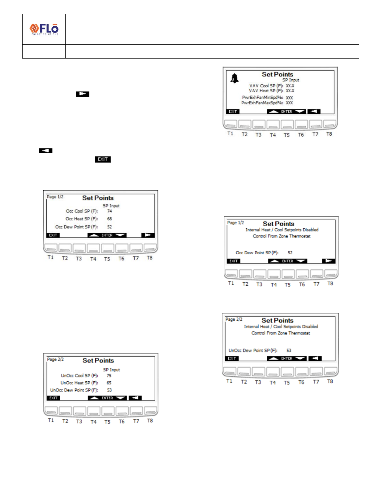
Set points .........................................................................6
Zone Thermostat Control.........................................7
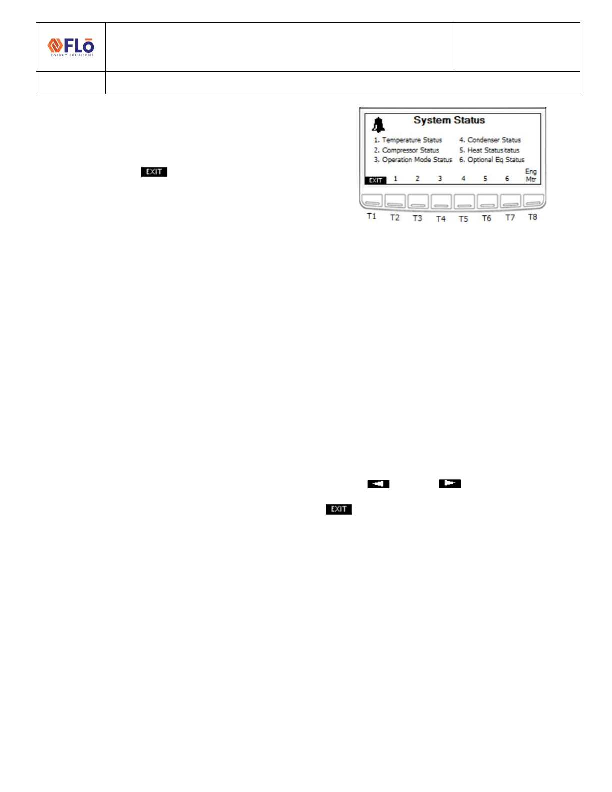
System Status...................................................................8
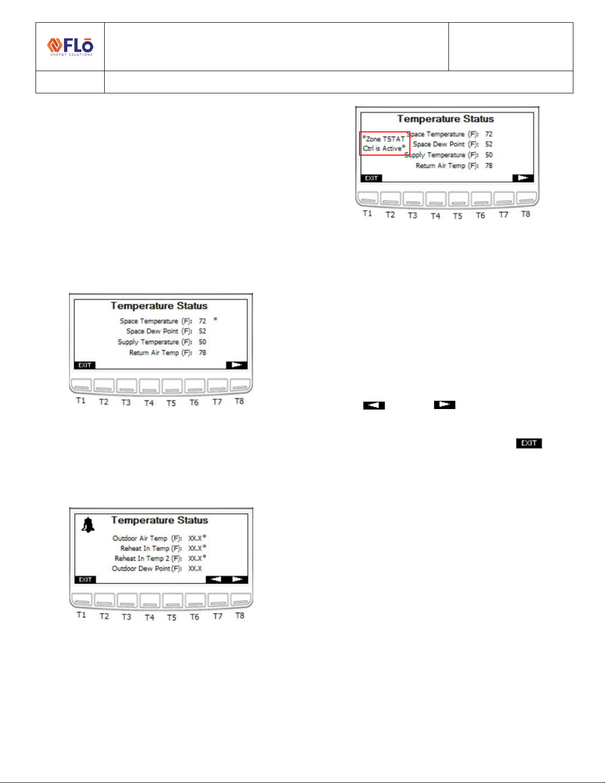
Temperature Status.................................................8
Zone Thermostat Control.........................................9
Compressor Status...................................................9
Chilled Water Status ..............................................11
Water Source Heat Pump (WSHP) ........................ 11
Operation Mode Status .........................................12
Condenser Status...................................................12
Water Source Heat Pump ..................................... 13
Condenser Information......................................... 13
Optional Equipment Status....................................13
VAV Status............................................................. 14
ERV Status ............................................................. 14
Power Exhaust Status............................................ 15
Zone Thermostat Status........................................ 15
Energy Meter Status ..............................................15
Alarms ............................................................................16
Alarm Status...........................................................16
Alarm History .........................................................18
Alarm Resets ..........................................................18
Sensor Status..................................................................19
Network Information .....................................................20
Modbus Network...................................................20
BACnet Network ....................................................20
Network Options....................................................21
Field Tech Menu ............................................................22
Sensor Offsets................................................................23
Pressure Sensors Offsets .......................................24
VAV Offsets............................................................24
Test Mode Descriptions.................................................24
System Test Modes........................................................25
Water-Cooled Condenser......................................26
Chilled Water Unit .................................................26
Air Balancing..........................................................26
Compressor Test Mode .........................................26
Damper Test Mode................................................27
Condenser Fan Test Mode.....................................27
Heat Test Mode .....................................................27
Reheat/ Reclaim Test.............................................27
Operational Test Modes ................................................28
Occupancy .............................................................28
Dehumidification ...................................................28
Comfort Cooling.....................................................28
Heat Test Mode .....................................................28
Fan Only Test Mode...............................................28
Feature Tests Modes .....................................................29
Sensor Verification.........................................................29
I/O Verification ......................................................29
Clear All Test Modes ......................................................31
Sensor Settings...............................................................31
Set Damper Positions and Exhaust Fan Interlocks.........32
Damper Positions...........................................................33
Input and Output Status ................................................34
Input Status............................................................34
Output Status.........................................................35
VAV Status .............................................................36
Demand Control Ventilation (DCV)................................36
Overrides........................................................................37
Input Overrides:.....................................................37
Output Overrides:..................................................38

Technical Guide
CN-IC1-12
Title:
i-Controller Visograph Navigation REV.201.05
EXTERNAL 3 1-5JULY2021
Compressor Overrides: ......................................... 39
Condenser Overrides: ........................................... 39
Other Overrides .....................................................40
VAV Overrides....................................................... 41
Energy Recovery Wheel (ERV) Overrides...............41
Hydronic Heating Overrides...................................41
Chilled Water Overrides.........................................42
Water Condenser...........................................................43
IMPORTANT:Read Before Continuing
i-Controller Unit Types: Some unit types such as Water-Source Heat Pumps and Chilled Water Units have screens that are
specific to that unit type. Refer to the ‘Additional Unit Types’ section for these specialized screens.
Working with Building Management Systems: Once an i-Controller Modbus or BACnet connection is established to the
Building Management System (BMS) and the controller is ONLINE, the BMS is the Master controller. All set point and
schedule changes are to be made at the BMS. Changes can be made on the i-Controller but are temporary and will be
overwritten by the BMS.
To make a temporary setting change perform the following steps:
1. Unplug the RS485 Connector from the i-Controller.
2. Wait at least 90 seconds, until the BMS Status on the Network Info screen on the Visograph reads Offline.
3. Adjust the necessary settings for testing or change the desired variable. (For instructions on how to navigate the
Visograph, please refer to the instructions below).
4. When testing/changes are complete, plug the RS485 Connector back into the RS485 port.
5. Once the Modbus/BACnet connection has been re-established and the controller shows Online on the Network
Info screen, double check the changed variable to ensure that it is correct.
6. If the changed variable has been over-written, then the variable change needs to be made at the BMS.

Technical Guide
CN-IC1-12
Title:
i-Controller Visograph Navigation for Version 201.04
EXTERNAL 1-5JULY2021
Introduction Screens
Introduction screens are displayed during controller
startup.
Figure 1. Introduction Splash screen
T8: Go to Main Menu
T2 + T3: Go to Version Info
Figure 2. Invalid Parameter File Message
Figure 3. Version Information screen
T2: Go to Overrides
T8: Go to Main Menu
File Descriptions
These are the base files used for the firmware and
controller parameters.
1. ISaGRAF Version: The version of the base program
inside the i-Controller. This field should match the
CRM field “Revision #” for a given unit.
2. VisoGraph Version: The version of the screens
shown on the Visograph.
3. Parameters Version: The version of the parameters
file loaded into the i-Controller.

Technical Guide
CN-IC1-12
Title:
i-Controller Visograph Navigation REV.201.05
EXTERNAL 5 1-5JULY2021
Main Menu
The Main Menu provides easy access to controller
information. When an alarm is present, the Alarm Bell
indicator is displayed. When one or more overrides are
present, the Warning indicator is displayed. The Main
Menu also displays the Date and Time and will indicate
when the unit is in a Test Mode.
To navigate the menu options, press the corresponding
key on the Visograph below the menu item number.
1. Schedule –Set weekly schedule for “Occupied” and
“Unoccupied” times.
2. Set Points –Define set points for cooling, heating,
and dehumidification modes during occupied and
unoccupied modes of operation.
3. Status –View temperature, compressor, and
operation mode status.
4. Alarms –View alarm status, sensor status, and
alarm resets.
5. Network Info –View controller IP settings and run
time, change controller Modbus address, and
change the Flō i-Controller date and time.
6. Field Technician Options –Parameters to be set by
a certified field technician only (password
protected). Press the (T1-T7) keys to access the
menu item.
Figure 4. Main Menu
T1: Go to Schedule
T2: Go to Set Points
T3: Go to Status
T4: Go to Alarms
T5: Go to Network Info
T8: Go to Logo screen
Schedules
A schedule is used to activate/ deactivate an event on a
specified day/ time. To create a scheduled event, use the
arrow and enter keys to select the day of the week of the
occurrence. Select the occupied or unoccupied period
and enter the hours and minutes for the event.
NOTE: See Important notice on page 5 before modifying
schedules.
Each day of the week is listed next to a corresponding
occupied time “Occ-Time” and unoccupied time “UnOcc-
Time”. The Flō unit will operate in “Occupied Mode” in
between the “Occ-Time” and “UnOcc-Time” listed for the
day of the week.
Each time on the schedule should correspond with the
store hours. All hours should be set in military time on a
24hr basis. (For Example: on Mondays, the occupied time
starts at 8:00am and the unoccupied time begins at
10:00pm. The above screen should read next to the “M”
8:00 under the “Occ-Time” and 22:00 under the “UnOcc-
Time”.) See Figure 5.
Figure 5. Monday 8am to 10pm Schedule
To change the occupied and unoccupied times:
1. Using the and buttons (T4 and T6,
respectively) navigate to the hour or minute that
you wish to change.
2. Press the (T5) button and the value should
blink.
3. Using the and buttons increase and
decrease the value as desired.

Technical Guide
CN-IC1-12
Title:
i-Controller Visograph Navigation REV.201.05
EXTERNAL 6 1-5JULY2021
4. Once the desired value has been reached press the
button to set the value.
5. Repeat steps 1-4 until all values in the schedule
have been updated.
6. Once all changes have been completed, press the
(T1) button to return to the Main Menu.
Figure 6. Schedule Configuration screen
T1: Go to Main Menu
T4: Scroll Up/Increase Value
T5: Enter (Select and Set Value)
T6: Scroll Down/Decrease Value
Zone Thermostat Control
Units configured to use a 2-Stage zone thermostat have
the option to use internal schedule or an external source
for an occupancy schedule. If internal schedule is used,
see above to set schedule. If the schedule is from an
external source, the display will be noted as shown below
and the schedule will need to be set from the external
source.
Figure 7. External Schedule Configuration screen
Set points
Set points are used as the cut in/ out for various i-
controller functions. The i-Controller Set Point
configuration section has 3 navigation screens.
The “Set Points” option should only be used if operation
set points are not being communicated to the Flō i-
Controller from a Building Management System (BMS).
If the Flō i-Controller is connected to a BMS over Modbus,
the set points shown on this screen will be automatically
updated with the set points entered in the BMS. The VAV
Set Points will only appear if VAV controls are connected
to the Flō unit. The set points limitations are as follows:
Cool SP: 60 - 85F
Heat SP: 50-80F
Dew Point SP: 48-60F
There must be a minimum of 4-degrees between the
heating and cooling set points. If set points are inputted
too close together, the program will automatically adjust
the set points per the following rules:
Outdoor Air Temp > 60 ˚F: Heating Set Point = Cooling Set
Point - 4 ˚F
Outdoor Air Temp < 50 ˚F: Cooling Set Point = Heating Set
Point + 4 ˚F
1. If the Flō i-Controller is not connected to a BMS,
perform the following steps to modify the set
points.
2. Using the and buttons (T4 and T6,
respectively) navigate to the “Occupied” set points
that you wish to change.
3. Press the (T5) button and the value should
blink.
4. Using the and buttons increase and
decrease the value as desired.
5. Once the desired value has been reached press the
button to set the value.

Technical Guide
CN-IC1-12
Title:
i-Controller Visograph Navigation REV.201.05
EXTERNAL 7 1-5JULY2021
6. Repeat steps 1-4 until all “Occupied” values have
been set.
7. Press the (T8) button to view the
“Unoccupied” set points.
8. Repeat steps 1-4 until all “Unoccupied” values have
been set.
9. Once all changes have been completed, press the
(T7) to return to the “Occupied” set points
screen or press the (T1) button to return to
the Main Menu.
Figure 8. Occupied Set Points - screen 1
T1: Go to Main Menu
T4: Scroll Up/Increase Value
T5: Enter (Select and Set Value)
T6: Scroll Down/Decrease Value
T7: Go to Previous Page
T8: Go to Next Page
Figure 9. Unoccupied Set Points - screen 2
Figure 10. VAV & Power Exhaust Fan Set Points - screen 3
Zone Thermostat Control
Units configured to use 2-Stage zone thermostats have
the internal heating and cooling setpoints disabled for
both Occupied and Unoccupied modes. However, the
internal Dew Point set point is still active for both modes.
Figure 11. Occupied Set Point screen 1 with TSTAT active
Figure 12. Unoccupied Set Point screen 2 with TSTAT active

Technical Guide
CN-IC1-12
Title:
i-Controller Visograph Navigation REV.201.05
EXTERNAL 8 1-5JULY2021
System Status
To navigate to the System Status menu options, press the
corresponding key on the Visograph below the menu
item number. Press the (T1) button to return to the
Main Menu.
1. Temperature Status –View the current
temperature in the treated space, space dew point,
supply duct temperature, return air temperature,
or outdoor conditions.
2. Compressor Status –View the current compressor
and suction pressure status.
3. Operation Mode Status –View the current
operation mode (Dehumidification, cooling, or
heating), reheat or reclaim status, current
occupancy, and other key system parameters.
4. Condenser Status –View the current condenser
fan status.
5. Heat Status –View the current heating operation
mode and stage status.
6. Optional Eq Status** –View current status of
optional connected equipment. This includes VAV
zones, ERV wheels, Power Exhaust, or Zone
thermostat inputs. Status will only appear if
optional equipment is present.
7. Energy Meter –View current power consumption.
** If Equipped
Figure 13. System Status screen
T1: Go to Main Menu
T2: Go to Temperature Status
T3: Go to Compressor Status
T4: Go to Operation Mode
T5: Go to Condenser Status
T6: Go to Heat Status
T7: Go to Optional Equipment Status**
T8: Go to Energy Meter**
Temperature Status
There are 2 temperature status screens that display the
reading of various temperature sensors throughout the
unit. NOTE: when an asterisk (*) is displayed to the right
of the value, the value is in override.
Use the (T7) and (T8) buttons to navigate
between the two “Temperature Status” pages. Press
(T1) to return to the System Status Menu.
1. Space Temperature: Temperature reading from
temperature probe mounted in the space.
2. Space Dew Point: Dew point calculated from the
temperature and humidity probe readings
mounted in the space.
3. Supply Temperature: Temperature reading from
temperature probe mounted in the supply air duct.
4. Return Air Temperature: Temperature reading
from temperature probe mounted in the return air
duct.
5. Outdoor Air Temperature: Temperature reading
from temperature probe mounted in underneath
the rain hood on the Flō unit.

Technical Guide
CN-IC1-12
Title:
i-Controller Visograph Navigation REV.201.05
EXTERNAL 9 1-5JULY2021
6. Reheat/Reclaim In Temp: Temperature reading
from temperature probe mounted in the
Reheat/Reclaim Stage 1 inlet.
7. Reheat/Reclaim In 2 Temp**: Temperature
reading from temperature probe mounted in the
Reheat/Reclaim Stage 2 inlet.
8. Outdoor Dew Point**: Dew point calculated from
the temperature and humidity probe readings
mounted underneath the rain hood of the Flō unit.
** If Equipped
Figure 14. Temperature Status screen 1 with Overrides Present
T1: Go to System Status Menu
T7: Previous Page
T8: Next Page
Figure 15. Temperature Status screen 2 with Overrides Present
Zone Thermostat Control
Units configured to use 2-Stage zone thermostats note
the control option on the Temperature Status screen.
Figure 16. Temperature Status screen 3 with TSTAT active
Compressor Status
There are 4 Compressor Status screens; however, Status
screens are only displayed for compressors equipped in
the unit. The Suction Pressure Status will only appear if
Compressor 2 is a digital scroll compressor (when 4
compressors are present), Compressor Status screens 3
and 4 will only be displayed when the unit is equipped
with a third and fourth compressor.
Use the (T7) and (T8) buttons to navigate
between the two “Compressor Status” pages. The second
“Compressor Status” page is only available if the Flō unit
contains more than two compressors. Press (T1) to
return to the System Status Menu.
1. Dig Comp # Operating Capacity: Digital
Compressor operating percentage.
2. Fixed Compressor # Status: Fixed Compressor
operating status; “ON” or “OFF”.
3. Suction Pressure for Comp #: Suction pressure
reading from the pressure transducer located on
the denoted Digital Compressor.
4. Suction Pressure Set Point: Suction pressure set
point set based on the current control strategy.
5. Compressor # Status: This will display the status of
each compressor. Possible status values include:
oOK: Compressor is running properly.
oComp High Dis Trip: Activated when a
compressor’s discharge pressure has
exceeded the safety limit (550PSI by
default). Compressor will instantly shut

Technical Guide
CN-IC1-12
Title:
i-Controller Visograph Navigation REV.201.05
EXTERNAL 10 1-5JULY2021
down and lock out until discharge drops to
an acceptable level.
oComp Low Suction Trip: Activated when a
compressor’s suction pressure dropped
below the safety limit (75PSI by default).
Compressor will instantly shut down and
lock out until suction rises to an acceptable
level.
oNo Comp Proof: Activated when the
compressor signal is on, but suction
pressure and discharge pressure are within
20PSI of each other.
oLow Suct Press: Activated when the suction
pressure decreases below the lower pressure
limit (80PSI).
oHigh Suct. Press: Activated when the suction
pressure increases above the upper pressure
limit (varies per mode) during dehumidification
or cooling call.
oHigh Dis Press Alarm: Activated when the
suction pressure increases above the upper
pressure limit (500PSI).
oSuct. Trans Fail: Activated when the suction
transducer reading is out of range.
oDis Trans Fail: Activated when the discharge
transducer is out of range.
oGradual Shutdown: Activated when the
discharge pressure of a digital compressor is
above the warning limit. Digital compressor will
gradually reduce capacity in 20% increments
until discharge pressure drops to an acceptable
level.
oOA Temp Comp Lockout: Activated when the
outdoor air temperature is too cold to allow
compressors to run.
oEconomizer Lockout*: Activated when
economizer mode is active.
Figure 17. Compressor Status screen 1
T1: Go to System Status Menu
T7: Previous Page
T8: Next Page
Figure 18. Compressor Status screen 2
Figure 19. Compressor Status screen 3
Figure 20. Compressor Status screen 4

Technical Guide
CN-IC1-12
Title:
i-Controller Visograph Navigation REV.201.05
EXTERNAL 11 1-5JULY2021
Chilled Water Status
Chilled Water Units will have a Chilled water status screen
in place of the Compressor status screen.
Figure 21. System Status screen
Figure 22. Chilled Water Status screen
Figure 23. Chilled Water Status screen 2
Water Source Heat Pump (WSHP)
When the unit is a WSHP the ‘Suction Pressure Setpoint’
will be replaced ‘Discharge Pressure Setpoint’ while the
unit is heating operation.
Figure 24. WSHP Compressor Status while in Heating

Technical Guide
CN-IC1-12
Title:
i-Controller Visograph Navigation REV.201.05
EXTERNAL 12 1-5JULY2021
Operation Mode Status
From the System Status Menu Press T4 to enter the
Operation Mode Status page.
1. Occupancy Mode: “Occupied” or “Unoccupied”
Mode will display based on the occupancy
schedule.
2. Current Mode: The second line will display the
unit’s operation mode. One of the following will
appear, based on the unit’s operation.
oStandby
oFan-Only
oHeat
oCool
oDehum
oDehum + Heat
oDehum + Cool
oPre-Emptive Dehum
oShutdown
oNet Disable
oReturn Temp Control**
oEcon Mode**
oHydronic Freeze Protection Heat (only on units
with Hydronic Heat equipped)
3. Amp Draw: Amperage reading from the 1-phase
current transducer.
4. Supply Fan Status: Status of the supply fan
operation will a value from 0-100%.
5. Compressor Capacity: Total compressor capacity
will display a value from 0-100%.
6. Heat Capacity: Total heat capacity will display a
value from 0-100%.
7. Reheat/Reclaim Status: Reheat or Reclaim Stage 1
“ON” or “OFF” when the coil is activated and
deactivated.
8. Reheat/Reclaim 2 Status**: Reheat or Reclaim
Stage 1 “ON” or “OFF” when the coil is activated
and deactivated.
9. Pre-Heat Status: If the pre-heat option is selected,
the pre-heat status will display “ON” or “OFF”.
10. CO2 Level (ppm)**: If a CO2 sensor option is
chosen, the CO2 level will be displayed in parts per
million (ppm). This is the CO2 control value. If more
than one CO2 sensor is being used, this value
represents the max CO2 value.
** If Equipped
Figure 25. Operation Mode Status screen
T1: Go to System Status Menu
T3: Go to Alarm Status
Condenser Status
The Condenser Status screen shows the status of all
condenser fans present on the unit.
Figure 26. Condenser Status screen
T1: Go to Status Menu
T3: Condenser Info

Technical Guide
CN-IC1-12
Title:
i-Controller Visograph Navigation REV.201.05
EXTERNAL 13 1-5JULY2021
Water Source Heat Pump
When the unit is a WSHP the Condenser Status screen will
display information for the water source condenser.
Figure 27. Condenser Status screen 1 when WSHP
Figure 28. Condenser Status screen 2 when WSHP
Condenser Information
The Condenser Info describes the condenser fan
sequence and operation.
Figure 29. Condenser Info screen
T1: Go to Condenser Status Menu
Optional Equipment Status
To view current status of optional connected equipment,
press T7 from the System Status Menu. Optional
equipment includes VAV zones, ERV wheels, Power
Exhaust, or Zone thermostat inputs. Status will only
appear if optional equipment is present.
Figure 30. Optional Equipment Status screen
T1: Go to Status Menu
T2: Go to VAV Status Menu
T3: Go to ERV Status Menu
T4: Go to Power Exhaust Status Menu
T5: Go to Zone Tstat Status Menu

Technical Guide
CN-IC1-12
Title:
i-Controller Visograph Navigation REV.201.05
EXTERNAL 14 1-5JULY2021
VAV Status
From the System Status Menu press the T7 button to
enter the Optional Equipment Status Menu page and
then T2 for VAV Status page.
1. VAV # Control Temp: The calculated control
temperature for the associated zone. If more than
one temperature sensor is being used for the
associated zone, this value represents the
calculated average of the temperature readings.
2. VAV Fan #: VAV Fan Status for associated zone.
Value will be “ON” or “OFF.”
3. VAV Fan Speed #: VAV Fan Speed for associated
zone. Value will be 0-100%.
4. VAV Booster #: VAV Booster Heater status for
associated zone. Value will be “ON” or “OFF.” If
modulate heat is being used, the value will be 0-
100%.
5. VAV Damper #: VAV Damper position for
associated zone. Value will be 0-100%.
The VAV Status screen displays state of VAV inputs and
outputs.
Figure 31. VAV Status screen
T1: Go to Status Menu
ERV Status
From the System Status Menu press the T7 button to
enter the Optional Equipment Status Menu page and
then T3 for ERV Status page.
The ERV Status screen displays state of ERV inputs and
outputs.
Figure 32. ERV Status screen
T1: Go to Status Menu
1. Free Dehum Mode: Displays whether the unit is
in “Free Dehum” Mode.
2. ERV Wheel: ERV Wheel Status. Value will be
“ON” or “OFF.”
3. ERV Power Exhaust: ERV Power Exhaust Status.
Value will be “ON” or “OFF.”
4. ERV Bypass Damper: ERV Bypass Damper
Position. Value will be “ON” if the damper is
open, or “OFF” if the damper is closed.
5. ERV Store Exhaust: ERV Store Exhaust Status.
Value will be “ON” or “OFF.”

Technical Guide
CN-IC1-12
Title:
i-Controller Visograph Navigation REV.201.05
EXTERNAL 15 1-5JULY2021
Power Exhaust Status
The Power Exhaust Status screen shows the exhaust fan
output status and current minimum and maximum speed
set points.
Figure 33. Power Exhaust Status screen
T1: Go to Optional Equipment Menu
Zone Thermostat Status
The Zone Thermostat Status screen shows the input
status of the 2-stage zone thermostat.
Figure 34. Zone Thermostat Status screen
T1: Go to Optional Equipment Menu
Energy Meter Status
When the unit is equipped to monitor energy conception,
the Energy Meter Status will display the unit consumption
and power factor.
Figure 35. Energy Meter Status screen
T1: Go to Status Menu
1. Real Energy (kWh): Displays the Real Energy
usage, in kilowatt-hours.
2. Real Power (kW): Displays the Real Power usage,
in kilowatts.
3. Power Factor: Displays the power factor.

Technical Guide
CN-IC1-12
Title:
i-Controller Visograph Navigation REV.201.05
EXTERNAL 16 1-5JULY2021
Alarms
To navigate to the following menu options, from the Main
Menu press T4 to enter the Alarms Menu page.
1. Alarm Status –View the status of alarms.
Navigate to this page when the bell in the upper
left corner appears to view which alarm has been
activated.
2. Sensor Status –View the status readings of
sensors. If a sensor failure is the cause for an
alarm, this page will show which sensor has
failed.
3. Alarm History –Displays a list of alarms and the
last time they transitioned from OFF to ON.
4. Alarm Reset –Contains necessary resets for
certain alarms. If a fan fail occurs, once the
problem has been resolved this page contains the
reset necessary to continue operation.
Figure 36. Alarms screen
T1: Go to Main Menu
T2: Go to Alarm Status
T3: Go to Sensor Status
T4: Go to Alarm History
T5: Go to Alarm Reset
Alarm Status
Press T1 to return to the Alarms Menu. Each alarm will
display “ALARM” when an alarm is present and “OK”
when no alarm is present.
1. Clogged Filter Alarm: Alarm activated when the
filters in the unit need to be replaced.
2. Fan Status: Alarm activated when a fan fail occurs.
3. Overflow Alarm: Alarm activated when a smoke
detection signal is sent from the space. This alarm
will cause the unit to shut down.
4. Phase Loss Alarm: Alarm activated when improper
voltage is supplied to the unit. This alarm will cause
the unit to shut down.
5. Smoke Det. Alarm: Alarm activated when a smoke
detection signal is sent from the space. This alarm
will cause the unit to shut down.
6. CO2 Level Status*: Alarm is activated when the
CO2 level in the space increases above the specified
ppm limit.
7. Ref Lk Status*: Alarm is activated if there is a leak
in the store’s refrigeration system. A digital signal is
received from the refrigeration rack controller that
signifies a leak has been detected. Once the signal
is received, the OAD of the Flō unit will open to
100% to flush the store.
8. Heat Status: Alarm is activated if a temperature
increase has not occurred after heat mode has
been activated for a certain period of time.
9. Sensor Failure: Displays “YES” when a sensor
failure is present.
10. Reclaim Status*: Notice is activated if the
reheat/reclaim inlet temperature has not increased
at least 5 ˚F, after heat reclaim has been enabled
for 15-minutes. Notice is automatically reset upon
heat reclaim disable. This notice will not trigger an
alarm in the unit.

Technical Guide
CN-IC1-12
Title:
i-Controller Visograph Navigation REV.201.05
EXTERNAL 17 1-5JULY2021
11. Comp Status: This will display the status of each
compressor. Possible status values include:
If multiple alarms are present, only the highest
priority alarm will appear. Alarms are listed top-to-
bottom by priority (with ‘Suct Trans Fail’ being the
highest priority, and ‘OK’ being the lowest).
oSuct Trans Fail: Activated when the
suction transducer reading is out of
range.
oDis Trans Fail: Activated when the
discharge transducer is out of range.
oComp High Dis Trip: Activated when a
Comp Proof Fail and High Dis Pressure
alarm activate together.
oNo Comp Proof: Activated when the
compressor signal is on, but suction
pressure and discharge pressure are
within 20PSI of each other.
oHigh Suct. Press: Activated when the
suction pressure increases above the
upper pressure limit (varies per mode)
during dehumidification or cooling call.
oLow Suct Press: Activated when the
suction pressure decreases below the
lower pressure limit (80PSI).
oHigh Dis Press Alarm: Activated when the
suction pressure increases above the
upper pressure limit (500PSI).
oOK: Compressor is running properly.
oComp Low Suction Trip: Activated when
a compressor’s suction pressure drops
below the safety limit (75PSI by default).
Compressor will instantly shut down and
lock out until suction rises to an
acceptable level.
oGradual Shutdown: Activated when the
discharge pressure of a digital
compressor is above the warning limit.
Digital compressor will gradually reduce
capacity in 20% increments until
discharge pressure drops to an
acceptable level.
oOA Temp Comp Lockout: Activated when
the outdoor air temperature is too cold to
allow compressors to run.
oEconomizer Lockout*: Activated when
the economizer is active.
*If Equipped.
Figure 37. Alarm Status screen 1
T1: Go to Alarm Menu
T8: Go to Next Page
Figure 38. Alarm Status screen 2
T1: Go to Alarm Menu
T7: Go to Previous Page

Technical Guide
CN-IC1-12
Title:
i-Controller Visograph Navigation REV.201.05
EXTERNAL 18 1-5JULY2021
Alarm History
The Alarm History will display a timestamp next to each
alarm indicating the last alarm occurrence.
Figure 39. Alarm History screen 1
Figure 40. Alarm History screen 2
Alarm Resets
Press T1 to return to the Alarms Menu. If a fan fail occurs
and the problem has been resolved, the fan fail alarm
needs to be reset to start normal operation. To reset the
fan, fail alarm, perform the following steps:
1. Using the and buttons (T4 and T6,
respectively) ensure that the “OFF” value is
highlighted.
2. Press the (T5) button and the value should
blink.
3. Using the and buttons increase and
decrease the value until “ON” appears.
4. Once the desired value has been reached press
the button to set the value.
5. Once the value has been set to “ON” the fan fail
alarm has been reset and the fan is ready for
operation.
6. The value will automatically reset to “OFF” after
5 seconds. Values will display as “ON/OFF” for
Fan Fail Reset, or “YES/NO” for Clear Alarms.
Figure 41. Alarm Resets screen
T1: Go to Alarms Menu
T4: Change value to ON
T5: Enter (Select and Set Value)
T6: Change value to OFF

Technical Guide
CN-IC1-12
Title:
i-Controller Visograph Navigation REV.201.05
EXTERNAL 19 1-5JULY2021
Sensor Status
Press T1 to return to the Alarms Menu. Each sensor status
will display “FAIL” if the sensor has failed and “OK” when
the sensor is still operational. Use the (T7) and
(T8) buttons to navigate between the two “Sensor Status”
pages.
The Outdoor Humidity and CO2 sensors on the first page
are optional and will not appear on the screen if these
options are not included on the unit.
There are three Sensor Status screens. Screen 3 is only
visible if the unit contains VAV, a hydronic heating coil, a
second space Temp, or a 2nd Dehum Probe.
Figure 42. Sensor Status screen 1
T1: Go to Alarms Menu
T7: Previous Page
T8: Next Page
Figure 43. Sensor Status screen 2
Figure 44. Sensor Status screen 3

Technical Guide
CN-IC1-12
Title:
i-Controller Visograph Navigation REV.201.05
EXTERNAL 20 1-5JULY2021
Network Information
The Network Information screens to displaythe Firmware
Version, Expansion Board status (Online/ Offline),
Building controller status (Online/ Offline), i-Controller
Address (Modbus or BACnet), Baud Rate, IP Address, and
Parameter File version.
The Network Information screen displays the Flō i-
Controller IP address, and status of the connection to the
Building Management System (BMS). If the Flō i-
Controller is connected to the BMS the status will show
“Online”, otherwise, it will show “Offline” if the BMS is
offline or the i-Controller is not connected.
For units on a Modbus network, this screen displays the
Modbus address (configurable), and the Modbus baud
rate. To change the Modbus address:
1. Using the and buttons (T4 and T6
respectively) navigate to the value that you wish
to change.
2. Once the value is highlighted, press the (T5)
button and the value should blink.
3. Using the and buttons increase and
decrease the value as desired.
4. Once the desired value has been reached press
the button to set the value.
5. Once all changes have been completed, press the
(T1) button to return to the Main Menu.
Modbus Network
The Modbus and BACnet Network information screens
display the communication status, address and
parameter version.
Figure 45. Modbus Network Information screen 1
T1: Go to Main Menu
T4: Scroll Up/Increase Value
T5: Enter (Select and Set Value)
T6: Scroll Down/Decrease Value
T8: Network Options
BACnet Network
Figure 46. BACnet Network Information screen 1
Table of contents