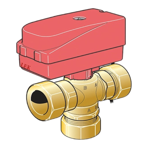
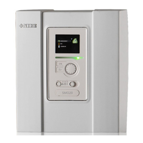
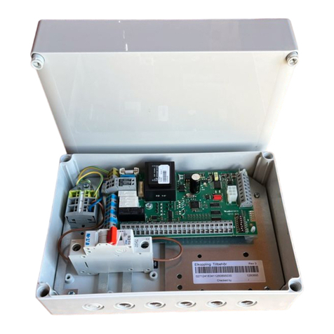
Nibe SMO 10 User manual

MOS GB 0923-4
SMO 10
511882
INSTALLATION AND MAINTENANCE INSTRUCTIONS
NIBE SMO 10


1NIBE SMO 10
General
System diagram ______________________________________ 3
Principle of operation _________________________________ 3
Abbreviations ________________________________________ 3
Front panel
Display______________________________________________ 4
Switch ______________________________________________ 5
Offset heating curve __________________________________ 5
Right keypad ________________________________________ 5
Left keypad__________________________________________ 5
Room temperature
Heating control system ________________________________ 6
Default setting _______________________________________ 6
Changing the room temperature manually _______________ 6
Setting with diagrams _________________________________ 7
Dealing with malfunctions
Low temperature or a lack of hot water __________________ 8
The hot water temperature does not reach the desired level
for ”Extra hot water” _________________________________ 8
High hot water temperature____________________________ 8
Low room temperature________________________________ 8
High room temperature _______________________________ 8
Switch position “ ”______________________________ 9
Alarm indications on the display _______________________ 10
Resetting the miniature circuit breakers _________________ 11
General information for the installer
Suspension _________________________________________ 12
Inspection of the installation __________________________ 12
Docking____________________________________________ 12
Changing menu type_________________________________ 12
Additional power without heat pump___________________ 12
Quick guide – menu setting additional power ____________ 12
Connection_________________________________________ 13
Docking – Hot water heating
Function ___________________________________________ 14
Connecting hot water heating_________________________ 15
Quick guide – menu settingsHot water heating___________ 15
Docking – Oil addition
Function ___________________________________________ 16
Connection oil addition_______________________________ 17
Quick guide – menu settingsOil addition ________________ 17
Docking – Immersion heater after
three way valve
Function ___________________________________________ 18
Connecting immersion heater after three way valve _______ 19
Quick guide – menu settings immersion heater
after three way valve_________________________________ 19
Docking – Exhaust air heat pump
Function ___________________________________________ 20
Connecting the exhaust air heat pump__________________ 21
Quick guide – menu settings when docking to
exhaust air heat pump _______________________________ 21
Docking – Pool heating
Function ___________________________________________ 22
Pool heating connection ______________________________ 23
Quick guide – menu settings pool heating _______________ 23
Docking – Gas boiler
Function ___________________________________________ 24
Connecting a gas boiler ______________________________ 25
Contents
Docking – Several heat pumps
Function ___________________________________________ 26
Quick guide – menu settingsseveral heat pumps__________ 26
Connecting several heat pumps________________________ 27
Docking – Extra shunt group
Function ___________________________________________ 28
Connecting extra shunt group _________________________ 29
Quick guide – menu settings extra shunt group __________ 29
Function description – Heating
Function ___________________________________________ 30
Quick guide – menu settings Heating ___________________ 31
Function description – Extra hot water
Function ___________________________________________ 32
Quick guide – menu settingsExtra hot water _____________ 32
Electrical connections
Screened 3 core cable between SMO 10
and a heat pump ___________________________________ 33
Connecting the outside sensor_________________________ 34
Connection of the flow and return line sensors___________ 34
Max boiler temperature/hot water heating_______________ 34
Load monitor _______________________________________ 35
External alarm ______________________________________ 35
Tariff ______________________________________________ 35
Terminal diagram ____________________________________ 36
Starting
Start-up with NIBE Air/water heat pump_________________ 38
Start-up without NIBE Air/water heat pump______________ 38
Menus to know _____________________________________ 38
Menu management
Changing parameters ________________________________ 39
Key lock ___________________________________________ 39
Quick movement ____________________________________ 39
Menu tree
Menu explanation
Main menus ________________________________________ 44
1.0 Hot water temp. _________________________________ 45
2.0 Supply temp. ____________________________________ 46
3.0 Supply temp. 2* _________________________________ 47
4.0 Outdoor temp. __________________________________ 48
5.0 Heat pump______________________________________ 48
6.0 Room temperature* ______________________________ 49
7.0 Clock __________________________________________ 49
8.0 Other adjustments _______________________________ 50
9.1.0 Heat pump settings _____________________________ 52
9.2.0 Add. heat settings ______________________________ 53
9.3.0 Operating settings. _____________________________ 54
9.4 Quick start ______________________________________ 56
9.5.0 Alarmlog______________________________________ 56
9.6.0 System Info____________________________________ 56
Technical specifications
Dimensions and setting-out coordinates_________________ 57
Component locations ________________________________ 58
List of components __________________________________ 59
Temperature sensor data______________________________ 59
Electrical circuit diagram ______________________________ 60
Accessories _________________________________________ 62
Enclosed kit ________________________________________ 63
Technical specifications _______________________________ 63

2NIBE SMO 10
General
In order to get the ultimate benefit from your NIBE SMO 10 you should read th-
rough these Installation and Maintenance Instructions.
SMO 10 is a control module designed to optimally control up to nine NIBE outdoor
air pumps together with other heating equipment.
Microprocessors ensure that the control module always works efficiently.
SMO 10 is a Swedish made quality product offering a long life span and safe ope-
ration.
Rights to make any design modifications are reserved. ©NIBE 2009.
To be filled in when the product has been installed
Serial number (103), should always be stated in all correspondence with NIBE.
089_ _ _ _ _ _ _ _ _ _ _
Installation Date
Installer
Type of docking
Accumulator/hot water heater
Number of heat pumps
Output size
Shunt group 2
Chosen output, immersion heater
Circulation pump setting (16), heating medium
Circulation pump setting (40), charge pump
Menu setting 2.1, “Heat curve”
Setting Offset heating curve
Date__________________________ Sign___________________________
General

3NIBE SMO 10
User guide
General
System diagram
VXV1
PG
SMO 10
HR
HR
HR
HR
P
VP
FG1* CP1
CP*
RG1
RG2
SV1
SV2
CP2 FG2
VVG
LP1
UG
AV
SÄV
TV RV
RV BV
BV
SF
SÄV
HR
UKV*
Principle of operation
SMO 10 is an advanced control module, which, together
with NIBE air/water heat pump and existing heating and
hot water equipment, creates a complete installation.
SMO 10 can be used for with several different connection
options. The base is the NIBE air/water heat pump, which,
in turn, can be docked on to electric boilers, oil-fired boil-
ers and accumulator tanks, for example, NIBE VPA.
Abbreviations
AV Shut-off valve
BV Non-return valve
EXP Expansion vessel with necessary safety equipment
FG1 Flow line sensor 1
FG2 Flow line sensor 2
HR Auxiliary relay
LP1 Charge pump 1
LP2 Charge pump 2
PG Boiler sensor
RG1 Return line sensor 1
RG2 Return line sensor 2
RV Control valve
SF Particle filter (Included in NIBE air/water heat
pump)
SV1 Shunt valve 1
SV2 Shunt valve 2
SÄV Safety valve
TV Drain valve
UG Outdoor sensor
VVC Hot water circulation
VVG Hot water sensor
VXV1 Three way valve 1
VXV2 Three way valve 2
CP1 Circulation pump 1
CP2 Circulation pump 2
NIBE air/water heat pump

4NIBE SMO 10
User guide
A BI II III I II
50.0 C
Hotwatertemperature
13.43
1.0
A
Front panel
A B A
I II III
Front panel
Display
Right keypad
Left keypad
Offset heating
curve
Compressor symbol
Atogether with compressor symbol, is displayed
when step 1 is in operation.
Btogether with compressor symbol, is displayed
when step 2 is in operation.
The compressor symbol alone indicates that the
compressor is to start, but is locked due to start
conditions in the air/water heat pump not being
met internally, e.g. stop temperature.
Addition. heat symbol
Indicates when the additional heater is connected.
The line indicates which power step/steps are cur-
rently connected.
Only shown if immersion heater is connected
Power stage Iis connected.
Power stage II is connected.
Power stage III is connected.
Only flashes when hot water is being heated by the
electrical addition.
A B A
Switch
Hot water symbol
Indicates when the “Extra hot water” function is
active.
A shown when 3 hour temperature increase is acti-
vated.
B shown when time based temperature increase is
activated, periodically or time controlled.
Circulation pump symbol
Shown when the circulation pump in the heating
system is in operation.
Heating system symbol
Shown when house heating with compressor is in
progress.
Defrosting symbol
Indicates when air/water heat pump defrosting is in
progress.
Display
First row:
Second row: Value of the current parameter.
Third row: Description of current display parameter.
“Hot water temp” is normally shown.
Fourth row: Shows the information symbols.
Menu number.
Pool charging in progress.
Key lock activated.
1.0
P

5NIBE SMO 10
User guide
Front panel
with three positions 1– 0– :
1Normal mode. All control functions connected.
0System fully shutdown.
Standby mode. This mode is used in the event
of operating disturbances. Additional heat out-
put is limited depending on selected connec-
tion option. See section “Dealing with malfunc-
tions”. NOTE! There is a risk of freezing at
outdoor temperatures below 0°C.
Operating mode
This button is used to set the required operating
mode with regard to permitting/blocking the circula-
tion pump and additional energy. The change does
not need to be confirmed with the enter button.
The current operating mode is shown on the display
when the button is pressed and the mode changes
when you continue to press the button. The display
returns to the normal display mode once the enter
button is pressed.
The different operating modes are:
Auto mode: SMO 10 automatically selects the op-
erating mode with reference to the outdoor temper-
ature. The circulation pump and addition are permit-
ted to run as needed.
Summer mode: Only production of hot water with
the air/water heat pump. The circulation pump and
additional heat are blocked. However, when “Extra
hot water” is activated the immersion heater is con-
nected.
Spring/Autumn mode: Only production of heat
and hot water with the air/water heat pump. The
circulation pump is operational. Additional heat
blocked. However, when “Extra hot water” is acti-
vated the immersion heater is connected.
NOTE! In the event of an alarm from the air/water
heat pump, the different modes are not displayed.
Extra Hot Water*
The “Extra hot water” function is activated for a pe-
riod of 3 hours using this button. The change does
not need to be confirmed with the enter button.
At activation, the hot water temperature increases
above the normal temperature, up to the set value.
Also see section ”Function description” – ”Extra hot
water ”.
No function.
Use the plus button to scroll through the menu
system (forwards) or increase the value of the se-
lected parameter.
Use the minus button to scroll through the menu
system (backwards) or decrease the value of the
selected parameter.
Use the enter button to select a lower menu in
the menu system, to activate a parameter change as
well as confirm a parameter change.
Also see the “Menu management” section.
This knob is used to change the heating curve's par-
allel offset and in doing so the room temperature.
Turning clockwise increases the room temperature.
When the knob is turned menu 2.0 is shown on the
display and the value for the calculated flow tem-
perature changes.
Also see the section Room temperature.
Right keypad
Offset heating curve
Switch Left keypad
* Requires additional power before three way valve or im-
mersion heater in hot water heater.
Key lock
A key lock can be activated by simultaneously pressing the
plus and the minus buttons. The key symbol will then be
shown on the display. The same procedure is used to deac-
tivate the key lock.

6NIBE SMO 10
User guide
Default setting
The basic heating is set using menu 2.1 and with the
“Heating curve offset” knob.
If you do not know the correct settings use the basic data
from the map opposite.
If the required room temperature is not obtained, readjust-
ment may be necessary.
NOTE! Wait one day between settings so that the tem-
peratures have time to stabilise.
Room temperature
Offset heating curve
Menu 2.1 Heat curve
9
Heat curve
2.1
Heating control system
The indoor temperature depends on several factors.
During the hot season, solar radiation and heat given off
by people and equipment are sufficient to keep the house
warm. When it gets colder outside, the heating system
must be started. The colder its gets, the hotter the radia-
tors must be.
This adjustment is made automatically, however the basic
settings must first be made on the boiler, see the section
“Default setting”.
Room temperature
Readjustment the default settings
Cold weather conditions
When the room temperature is too low, the “Heat
curve” value is increased in menu 2.1 by one incre-
ment.
When the room temperature is too high, the “Heat
curve” value is lowered in menu 2.1 by one incre-
ment.
Warm weather conditions
If the room temperature is low, increase the heating
curve offset setting by one step.
If the room temperature is high, reduce the “Heating
curve offset” setting by one step.
Changing the room temperature manually
If you want to temporarily or permanently lower or raise
the indoor temperature relative to the previously set tem-
perature, turn the “Heating curve offset” knob anticlock-
wise or clockwise. One to three lines approximately repre-
sents a one degree change in room temperature.
NOTE! An increase in the room temperature may be in-
hibited by the radiator or floor heating thermostats, if so
these must be turned up.

7NIBE SMO 10
User guide
Room temperature
“Heat curve” in menu 2.1 and
“Max supply temp.” in menu 2.4 are
adjusted according to the heating system
in question.
NOTE!
Setting with diagrams
The heating control system on the SMO 10 is controlled by
the outside temperature. This means the flow temperature
is regulated in relation to the current outdoor temperature.
The diagram is based on the dimensioned outdoor temper-
ature in the area and the dimensioned supply temperature
of the heating system. When these two values “meet”,
the heating control's curve slope can be read. This is set on
menu 2.1 “Heat curve”.
A suitable value is set using the knob on the front panel,
“Offset heat curve “. A suitable value for floor heating is
-1 and for radiator systems -2.
Offset heating curve
Menu 2.1 Heat curve
9
Heat curve
2.1
Shifting the heating curve -2
15 14 13 12 11 10
9
8
7
6
5
4
3
2
1
- 40 °C
UTETEMPERATU
R
- 10
0
10
- 5
+ 5
30
40
50
60
70
°C
FRAMLEDNINGSTEMPERATUR
- 20 - 30
FÖRSKJUTNING
VÄRMEKURVA (
-
2)
VÄRMEKURVA
HEATING CURVE
OFFSET HEAT CURVE
SUPPLY TEMPERATURE
OUTSIDE TEMPERATURE
Shifting the heating curve 0
30
40
50
60
70
°C
FRAMLEDNINGSTEMPERATUR
- 40 °C
UTETEMPERATUR
- 10
0
10 - 20 - 30
15 14 13 12 11 10 9
8
7
6
5
4
3
2
1
VÄRMEKURVA
- 5
+ 5
FÖRSKJUTNING
VÄRMEKURVA (0)
HEATING CURVE
OFFSET HEAT CURVE
SUPPLY TEMPERATURE
OUTSIDE TEMPERATURE
1514 13 12 11 10
8
7
6
5
4
3
2
1
- 40 °C
UTETEMPERATUR
- 10
0
10
- 5
+ 5
30
40
50
60
70
°C
FRAMLEDNINGSTEMPERATUR
- 20 - 30
FÖRSKJUTNING
VÄRMEKURVA (+2)
9
VÄRMEKURVA
HEATING CURVE
SUPPLY TEMPERATURE
OFFSET HEAT CURVE
Shifting the heating curve +2
OUTSIDE TEMPERATURE

8NIBE SMO 10
User guide
Dealing with malfunctions
Numbers between brackets refer to section ”Technical
specifications” – ”List of components”.
If the operating disturbance cannot be rectified by means
of the following, an installation engineer should be called. If
necessary set the switch to “ ” (manual shunt opera-
tion necessary).
Low temperature or a lack of hot water
QAir in boiler or system.
QLarge amounts of hot water were used.
QCircuit or main MCB tripped.
QPossible earth circuit-breaker tripped.
QMixer valve set too low.
QSwitch (8) set to “0”.
QTripped Miniature circuit-breaker (7) or Fine-wire fuse
(33). See “Dealing with malfunctions” – “Resetting the
miniature circuit breakers”.
QLoad monitor or external control may have been blocked
the electrical output.
QIncorrectly set values for hot water production.
The hot water temperature does not reach the
desired level for ”Extra hot water”
QAn alarm has been triggered, which blocks the extra hot
water.
QMaximum boiler temperature, knob (102) on the EBV
card (2), is set too low. This temperature should be set
10 °C above the set value in menu 9.1.14.
QMax power output, knob (101) or fuse rating, knob
(100), is set too low.
High hot water temperature
QMixer valve set too high.
QIncorrectly set values for hot water production.
Dealing with malfunctions
Low room temperature
QAir in boiler or system.
QCircuit or main MCB tripped.
QPossible earth circuit-breaker tripped.
QTripped Miniature circuit-breaker (7) or Fine-wire fuse
(33). See “Dealing with malfunctions” – “Resetting the
miniature circuit breakers”.
QAutomatic heating control system settings not correct.
Q24 hour setting incorrectly set so that night reduction is
active during the day.
QCirculation pump stopped.
QInitial pressure in expansion vessel too low. This is indi-
cated by low pressure on the pressure gauge. Contact
the installer.
QLoad monitor or external control may have been blocked
the electrical output.
High room temperature
QIncorrect values set on the automatic heating control
system.

9NIBE SMO 10
User guide
Switch position “ ”
Dealing with malfunctions
Reserve operation
During this stage, electronic control is not available and
the display is off. The automatic heating control system is
deactivated and mixing is performed manually.
The charge pump (LP1), circulation pump (CP1), additional
heater (TS2) and heating cartridge in the accumulator are
in operation.
In cases when oil addition (or electricity/gas addition with
shunt) is used, the boiler’s shunt must be operated manu-
ally.
Terminals 3, 8, 9, 14, 18, 20 and 26 on the terminal block
(11) are always powered.
As SMO 10 can be connected to a large
number of external units, these should also
be checked.
NOTE!

10 NIBE SMO 10
User guide
Dealing with malfunctions
LP alarm
This information is shown when the low pressure pres-
sostat in the air/water heat pump has tripped. SMO 10
switches to additional power*.
The alarm may be due to a frozen evaporator or reduced
air flow through the evaporator. The information disap-
pears when the pressostat is reset and the air/water heat
pump has been restarted. The alarm is reset in menu 5.2.
Sensor alarm
This information is shown when a temperature sensor in
the air/water heat pump stops working. SMO 10 switches
to additional power*.
The alarm may be due to an open-circuit or incorrect in-
stallation. The information disappears when the cause is
remedied and the air/water heat pump has been restarted.
The alarm is reset in menu 5.2.
LP ALARM 1
1.0
HP Alarm
This information is shown when the high pressure pres-
sostat in the air/water heat pump has tripped. SMO 10
switches to additional power*.
The alarm may be due to too low charge flow. The infor-
mation disappears when the pressostat is reset and the
air/water heat pump has been restarted. The alarm is reset
in menu 5.2.
HP ALARM 1
1.0
M-prot. alarm
This information is shown when the motor cut-out in the
air/water heat pump has tripped. SMO 10 switches to ad-
ditional power*.
The alarm may be due to dropped phase because of
tripped fuses or incorrectly set motor cut-out. The infor-
mation disappears when the fault is remedied and the
air/water heat pump has been restarted. The alarm is reset
in menu 5.2.
M-PROT. ALARM 1
1.0
COM. ALARM 1
1.0
SENSOR ALARM 1
1.0
Com. alarm
Error text is displayed when contact between SMO 10 and
the air/water heat pump is lost. SMO 10 switches to ad-
ditional power*.
The alarm may be due to a wiring short-circuit or lost
power to the air/water heat pump. The information disap-
pears when both SMO 10 and the air/water heat pump are
restarted.
NOTE! SMO 10 must be powered within 5 minutes after
the air/water heat pump restarts and communication be-
tween the products is resumed. The alarm is reset in menu
5.2.
* Means that the compressor is blocked. The flow tem-
perature is forced to the set minimum temperature in
menu 2.3 (can be removed in menu 9.3.17).
Alarm indications on the display
Other information about any operational faults or reac-
tions can also be shown on the display besides the stand-
ard information. This type of information is only shown
in menu 1.0 (The display always automatically returns to
menu 1.0 approximately 30 minutes after the last button
was pressed). This information alternates with menu 1.0’s
standard information. At the same time the display’s back-
ground lighting flashes.
The number to the far right in the display shows the rel-
evant heat pump. 0 stands for an alarm outside the heat
pump.
HWsens. alarm
This information is shown when a fault on the hot water
temperature sensor has been registered. SMO 10 is force-
run solely for hot water charging and automatic mode is
engaged.
The alarm may be due to faulty sensors or a broken sensor
cable. The information disappears when the fault is rem-
edied and the alarm is reset in menu 9.3.6.
HWSENS. ALARM 0
1.0
Therm. cutout
Shown when any temperature limiter has tripped.
The compressor and the immersion heater are blocked,
any set automatic operations are disabled as the operating
mode switches to spring/autumn, (circulation pump in op-
eration). Only applies if a temperature limiter is connected
to terminal block (11) terminals 33 and 34.
The information disappears when the fault is remedied
and the alarm is reset in menu 9.3.6.
THERM. CUTOUT 0
1.0

11NIBE SMO 10
User guide
Resetting the miniature circuit breakers
The miniature circuit breaker (7) is located above the circuit
board on the right hand side under the cover of SMO 10.
Normal mode of the miniature circuit breakers is ”1” (to
the left).
7
Dealing with malfunctions
SUPsens alarm
This information is shown when a fault on the flow tem-
perature sensor has been registered. SMO 10 is force-run
solely for hot water charging, any set automatic operations
are disabled and the operating mode switches to summer.
The alarm may be due to faulty sensors or a broken sensor
cable. The information disappears when the fault is rem-
edied and the alarm is reset in menu 9.3.6.
SUPSENS ALARM 0
1.0
IHsens. alarm
This information is shown when a fault on the immersion
heater temperature sensor has been registered. Immersion
heater operation is blocked, any set automatic operations
are disabled as the operating mode switches to spring/au-
tumn.
The alarm may be due to faulty sensors or a broken sensor
cable. The information disappears when the fault is rem-
edied and the alarm is reset in menu 9.3.6.
IHSENS. ALARM 0
1.0
REPLACED SENSOR
This information is displayed when sensors in the heat
pump are incorrectly installed. SMO 10 switches to addi-
tional power*.
The information disappears when the cause is remedied
and the heat pump has been restarted.
DEFROSTING TIME
This information is shown when defrosting in the heat
pump has failed three times in succession. Check the
temperature on the return line sensor (menu 5.14). If it is
below 10 °C the heat pump will not defrost. Check the
temperature on the evaporator sensor (menu 5.10). If it is
higher than the outdoor air temperature (menu 5.9) dur-
ing compressor operation the heat pump does not defrost.
The information disappears when the cause is remedied
and the heat pump has been restarted.
REPLACED SENSOR 1
1.0
DEFROSTING TIME 1
1.0
SHORT OP TIME
This information is displayed when the operating time of
the heat pump has been less than 2 minutes 3 times in a
row. SMO 10 switches to additional power*.
The information disappears when the cause is remedied
and the heat pump has been restarted.
PERMANENT HOT GAS
This information is displayed when hot gas in the heat
pump exceeds 120 °C. Becomes continuous after three
repetitions within 240 minutes. SMO 10 switches to addi-
tional power*.
The information disappears when the cause is remedied
and the heat pump has been restarted.
PHASE ERROR
This information is displayed when the compressor in
F20XX has the incorrect direction of rotation. When start-
ing for the first time or after work in the distribution board
see ”Commissioning and adjusting” – ”Start-up and
inspection” in F20XX Installation and Maintenance instruc-
tions. SMO 10 switches to additional power*.
The information disappears when the cause is remedied
and F20XX has been restarted.
SHORT OP TIME 1
1.0
PERMANENT HOT GAS 1
1.0
PHASE ERROR 1
1.0

12 NIBE SMO 10
Installation / Adjustment
405
406
328
276
64
9
37
38,1
Ø 6
Docking
The safety equipment must be installed in accordance with
current regulations for all docking options. See www.nibe.
se/dockning for more docking options.
Changing menu type
Not all menus are visible from the outset, they require ac-
tivation in menu 8.1.1. Three different menu types can be
chosen. Menu type for relevant menu is marked in section
”Menu tree”.
Normal, covers the normal user's needs.
Extended, shows all menus except the service menus.
Service, shows all menus, returns to normal 30 minu-
tes after the last button was pressed.
N
U
S
Inspection of the installation
Current regulations require the heating installation to be
inspected before it is commissioned. The inspection must
be carried out by a suitably qualified person and should be
documented. The above applies to installations with a clo-
sed expansion vessel. If the electric boiler or the expansion
vessel is replaced, the installation must be inspected again.
General information for the installer
Suspension
SMO 10 is attached to a wall using four screws. There are
two holes on the reverse for hanging SMO 10 and two
through holes in the electrical connection area.
General information for the installer
Quick guide – menu setting additional
power
Menu 9.3.2 Add. heat mode
Additional heat mode is activated when “Yes” is
shown on the display screen, otherwise “No” is
shown. When the additional heat mode is activated,
the immersion heater respective circulation pump
cannot be blocked with the operating mode button.
The factory setting is “No”.
Operation without heat pump!
Additional power without heat pump

13NIBE SMO 10
Installation / Adjustment
LEK
General information for the installer
Connection
SMO 10 must be installed via an isolator switch with a mi-
nimum breaking gap of 3 mm.
Disconnect the control module before insulation testing
the house wiring.
The installer is responsible for ensuring that there is suf-
ficient strain relief for the cable. Cables are lead in through
the ”knock outs” in the underside (2x Ø20mm and 14x
Ø16mm, cable glands are not supplied).
LEK
Knock outs Terminal block (11)
EBV-card (2)
Terminal block (14)
Terminal block (4),
communication air/wa-
ter heat pump
To prevent interference, sensor cables and
communication cables must be separated
(min 20 cm) from high voltage cable when
cable routing.
NOTE!
Work behind screwed covers may only
be carried out under the supervision of a
qualified installation engineer.
NOTE!
Electrical installation and service must
be carried out under the supervision of a
qualified electrician. Electrical installation
and wiring must be carried out in accord-
ance with the stipulations in force.
NOTE!

14 NIBE SMO 10
Installation / Adjustment
VP
HR
LP1
UG
VVG
VXV1
SMO 10
SÄV
HR
RV BV
BV
HR
Docking – Hot water heating
Function
The air/water heat pump prioritises hot water charging via
a three way valve(VXV1).
Hot water heating is started and stopped by the tempera-
ture at the hot water sensor (VVG).
In cases where the additional heater is located after the
three way valve, the hot water is heated by the hot water
heater’s immersion heater when additional heat is acti-
vated.
Docking – Hot water heating
NOTE!
To prevent interference, sensor cables and communication
cables must be separated (min 20 cm) from high voltage
cable when cable routing.
NIBE air/water heat
pump

15NIBE SMO 10
Installation / Adjustment
Docking – Hot water heating
Connecting hot water heating
The three-way valve (VXV1) is connected to terminal 17
(230 V during hot water production), 18 (L1) and 19 (N)
on terminal block (11).
The hot water sensor (VVG) is installed in the hot water
accumulator tank’s submerged tube.
To measure the precise values the sensor must make good
contact with the measuring point. This sensor must be
connected to terminals 43 and 44 on the terminal block
(11).
The immersion heater in the hot water heater must be
used in cases where the additional heater is located after
the three-way valve. Connect to terminals 26 (230 V) and
27 (N) on terminal block (11).
If hot water circulation (VVC) is to be used, connect the
pump to terminals 28 (230 V) and 29 (N) on terminal block
(11).
See section “Electrical connection” – “Terminal diagram”
for complete terminal diagram.
VV VVC
N
L
-
Elpatron
V
armvatten
A2
A1
VXV 1
T
N
VV
+
LA
VV
11
Quick guide – menu settings
Hot water heating
Menu 1.1 Start temperature HW
The temperature when the heat pump starts to work
with the hot water heater is set here.
The value can be set between 25 and 50 °C. The fac-
tory setting is 45 °C.
Menu 1.2 Stop temperature HW
The temperature when the heat pump/immersion
heater should stop heating the water is set here.
The value can be set between 30 and 80 °C. The fac-
tory setting is 50 °C.
Menu 1.6 HW run time
How long hot water heating has been in progress is
shown here (accumulated).
Menu 8.5.0 Period settings
Time periods for heating and hot water production
are set in the sub-menus for this menu.
Menu 9.3.15 Block HW/Heating
Deselection can be made here if there is no hot wa-
ter or heating demand.
The options are “No hot water”, “No heating” or
“HW+heating”. Factory setting “HW+heating”.
Immersion
heater, hot
water

16 NIBE SMO 10
Installation / Adjustment
VXV1
PG
SMO 10
HR
HR
HR
HR
P
FG1* CP1
RG1
SV1
VVG
LP1
UG
SÄV
VP
HR
RV BV
BV
CP* UKV*
SMO 10 controls air/water heat pump, oil-fired boiler,
circulation pumps, shunts, etc. The air/water heat pump
works with floating condensing against the heating system
and prioritises hot water charging via the reversing valve
(VXV1). The heat pump works in stage 1 or stage 2 de-
pending on the outdoor air temperature.
The oil boiler starts when the number of degree minutes
is reached. If the temperature at the boiler sensor (PG)
reaches the set start level the shunt valve starts to regulate
according to set period and impulse times. If the tempera-
ture in the boiler drops below the preset temperature, the
shunt valve closes.
If the heat pump cannot meet the heating requirement,
the oil-fired boiler is started and additional heat is shunted
in.
In combined mode, the three-way valve (VXV1) is open
towards the heating system.
NOTE!
To prevent interference, sensor cables and communication
cables must be separated (min 20 cm) from high voltage
cable when cable routing.
Function
Docking – Oil addition
NIBE air/water heat pump
Docking – Oil addition
NIBE air/water heat pump docked to the oil-fired/pellet boiler together with SMO 10 and water heater (floating
condensing)

17NIBE SMO 10
Installation / Adjustment
Docking – Oil addition
Connection oil addition
The oil boiler is controlled by a relay (TS2) and connected
to terminals 20 and 21 (N) on the terminal block (11).
The shunt valve (SV1) is connected to terminals 11 (230 V
closing signal), 12 (230 V opening signal) and 13 (N).
Boiler temperature sensor (PG) is connected to terminals
41 and 42, terminal block (11).
See section ”Electrical connection” – ”Terminal diagram”
for complete terminal diagram.
SV1
-+N
11
TS2
TS1
TS3
Tillsats El
Var
Quick guide – menu settings
Oil addition
Menu 9.2.3 Docking type
The relevant docking option is selected here:
QVVM
QSMO Oilburner
QSMO El. after
QSMO Vent. Air
QSMO El before
Factory setting is “SMO Oilburner ”.
Select “SMO Oilburner ”.
Menu 9.2.1 Start add. heat.
The degree minute deficit that must be set before
the additional heat supply is activated is set here.
A value between -1000 and -30 can be set . The fac-
tory setting is -400.
Menu 9.2.8 Oil burner temp.
The oil boiler’s temperature is shown in °C here.
Menu 9.2.9 Oil b. start temp.
The oil boiler temperature must be set before the
shunt valve is permitted to open.
The value can be set between 10 and 65 °C. The fac-
tory setting is 55°C.
Menu 9.2.10 Oil b. min. time
Number of hours the oil boiler is to be active.
The value can be set between 1 and 12 hours. The
factory setting is 2 hours.
Addition

18 NIBE SMO 10
Installation / Adjustment
VP
P
HR
LP1
UG
VVG
VXV1
RG1
CP1
FG1*
ELK
SMO 10
AV
SÄV
AV
AV
BV
HR
HR
VVB/ACK
RV BV
BV
HR
UKV*
CP*
Docking – Immersion heater after three way valve
NIBE air/water heat pump
Docking – Immersion heater after three way valve
NIBE air/water heat pump docked to the immersion heater after the three way valve together with SMO 10 and
water heater (floating condensing)
Function
SMO 10 controls air/water heat pump, immersion heater,
circulation pumps, three way valves, etc. The air/water
heat pump works with floating condensing against the
heating system and prioritises hot water charging via the
reversing valve (VXV1). The air/water heat pump works in
stage 1 or stage 2 depending on the outdoor air tempera-
ture and the heating requirement.
If the air/water heat pump does not manage the heat-
ing demand, additional heat from the immersion heater is
engaged.
When additional heat is engaged, hot water is heated us-
ing the immersion heater in the hot water heater.
In combined mode, the three way (VXV1) is open towards
the heating system.
NOTE!
To prevent interference, sensor cables and communication
cables must be separated (min 20 cm) from high voltage
cable when cable routing.
Other manuals for SMO 10
2
Table of contents
Other Nibe Controllers manuals
Popular Controllers manuals by other brands

CBS ArcSafe
CBS ArcSafe RSA-107 Installation and operation

Cisco
Cisco SCE 1000 and quick start guide

Emerson
Emerson Dixell XM668D Installing and operating instructions

Wallgate
Wallgate WEX300 product manual

THOMSON
THOMSON MEC 310#GENSET CONTROLLER OPTION J-CANBUS... manual

Fuji Electric
Fuji Electric PXZ Series Operation manual

Soyal
Soyal AR-721E user guide

AND
AND Weighing Indicator AD-4335 instruction manual

Intermatic
Intermatic ReadySet PE24RSVA Installation and operation manual

Pride Mobility
Pride Mobility LiNX Controller Basic operation instructions

ESK Schultze
ESK Schultze ERM5 Installation and operating instructions

Buderus
Buderus AM10 Installation and user manual