manuals.online logo
Brands
  1. Home
  2. •
  3. Brands
  4. •
  5. Espa
  6. •
  7. Smoke Alarm
  8. •
  9. Espa MAGPRO-HSD1 User manual

Espa MAGPRO-HSD1 User manual

>30cm >30cm
MAGPRO-HSD1
Intelligent analogue addressable fire
alarm heat and optical smoke detector
Distributor: Elite Security Products Ltd,
Unit 7 Target Park, Shawbank Road
Lakeside, Redditch B98 8YN, UK
http://www.espuk.com
Manufacturer: Teletek Electronics JSC
14A Srebarna Str, 1407 Sofia, Bulgaria
EN 54-5: 2000/ A1: 2002,
EN54-7: 2000/ A2: 2006
Detector Class A1/R
DoP No: 034
Tested by EVPU: N.B.1293
1293 15
Installation Instructions
ATTENTION: Read carefully this installation instruction before installing the device.
This manual is subject to change without notice errors and omissions accepted.
<7m - MAGPRO-HSD1
<5m
-
MAGPRO-SD1
MAGPRO-HD1,
18020165, RevB, 02/ 2015
GENERAL DESCRIPTION
MAGPRO-HSD1 is аn addressable combined temperature and optical smoke detector designed for use with ESP MAGPRO fire alarm panels.
The detector is powered from the panel and can be controlled via its communication protocol.
The MAGPRO-HSD1 is compatible with detector base MAGPRO-DB.
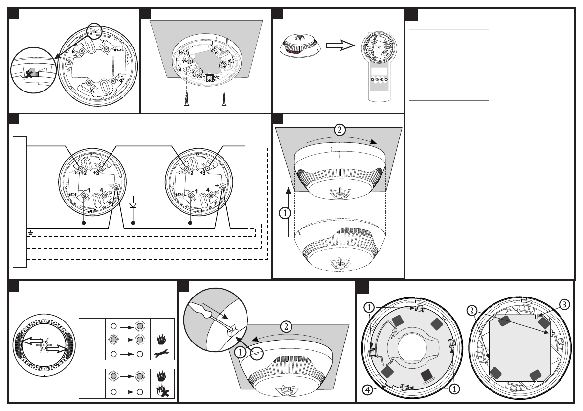
INSTALLATION
1. Select a suitable position for installation. Note: Do not install the detector near sources of steam, condensation or smoke and close to natural
heat sources.
2. Mount the detector base to the required surface with suitable fixings.
3. Connect the detector base to the fire panel using the wiring diagram.
ATTENTION: Disconnect the loop power before installing the detector!
4. To activate the anti tamper lock option on the detector base carefully remove the small tooth shown in Fig2 using short nose snips.
5. To locate the detector onto the base align the line mark on the detector with the short line mark on the detector base. Rotate the detector
clockwise until the short line mark on the detector coincides with the long mark on the base and a “click” is heard.
6. If removal of the detector is required after the detectors anti tamper lock function has been selected a small flat blade screwdriver should be
inserted into the aperture on the side of the detector base. Lightly press with the screwdriver at the same time as rotating the detector head in
a counter-clockwise direction.
TECHNICAL SPECIFICATIONS TECHNICAL SPECIFICATIONS
Operating Voltage Range . . . . . . . . . . . . . . . . . . . . . . . 15 - 32VDC (Nom. 27VDC)
Consumption in quiescent state, no communication ..< 160μA@27VDC
Consumption in quiescent state, with communication .< 200μA@27VDC
Consumption in alarm state, with communication ....6.5mA
Class (in accordance with EN54-5) ...............A1/R
Sensitivity level (*in accordance with EN54-7) . . . . . . . High/ Normal*/ Middle/ Low
Protected area (in accordance with EN54-5/7)......up 120m²
Installation height (in accordance with EN54-5/7)....up 16m
Output in alarm state at terminal RI (terminals 4/1) ...7.5 mA (max)/ 7.5V
2 2
Wire Gauge for terminals . . . . . . . . . . . . . . . . . . . . . . . 0.4mm ё 2.0mm
Relative humidity resistance.....................(93 ± 3)% @ 40°C
Dimensions (incl. base) ........................ø103mm, h 49mm
Essential characteristics Performance
Performance under fire conditions Pass
Operational reliability Pass
Durability of operational reliability and response delay: temperature resistance Pass
Durability of operational reliability: humidity resistance Pass
Durability of operational reliability: shock and vibration resistance Pass
Durability of operational reliability: corrosion resistance Pass
Durability of operational reliability: resistance to ingress Pass
IP30
-10°C ÷ +60°C
Installation
~125g
Indoor
Outdoor
!
Without base
7
5
6LED Indication
4Connection diagram
!Test and Maintenance
TESTING THE DETECTOR
1. Apply power to the detector.
2. Wait for 30 sec.
3. Introduce artificially generated smoke (and/ or heat)
directly beneath the detector. Within 8 sec the detector
will enter into fire condition. Both LEDs will illuminate.
4. Power off the detector for 2 sec minimum. After
resetting the detector will enter into duty mode and both
LEDs will extinguish.
SERVICE MAINTENANCE
1. Inspection for visible physical damage - weekly.
2. Operational test in real conditions - monthly.
3. Check and clean dust contamination - six months.
4. Check and clean base and head contacts and
connections - annually.
CLEANING AND MAINTENANCE
1. Remove the detector from its base.
2. Remove the inner protective cover - press the four
clips (1) with a plain screwdriver gently down to unlock
the cover from the detector’s body.
3. Dismount the PCB from the supporting clips (2).
4. Clean the smoke chamber.
5. Mount the PCB back to the detector’s body - as a
reference point use the side with a cut-out (3). Rotate the
PCB until the cut-out coincides with the pin on the inner
part from the detector body. Gently press the PCB down
to fix in place.
6. Mount the inner protective cover - the mark with a
rectangular shape (4) fits with the channel at the inner
side of the detector’s body and the contact plates on the
PCB coincide with the four openings on the protective
cover. Press gently down until a click is heard.
7. Mount the detector back to its base and test for correct
operation and LED indication.
!Maintenance
3
12
Base MAGPRO-DB Address programming
You may also program the
address directly from the
fire panel.
Down
Right
Up
Modify
Esc
Enter
MAGPRO
PROG
Fire Panel
Earth (Earth point)
RI
(Remote
indicator)
+Loop
-Loop
-Loop (Negative Loop Wire)
+Loop (Positive Loop Wire)
Blinking 10 sec OK
Light on
Light off
Light on
Light off
1. Blinking is enabled
2. Blinking is disabled
The LED indication can be enabled/ disabled
from the control panel.

Popular Smoke Alarm manuals by other brands

Nemaxx SP5-NF Original operating instructions

Nemaxx

Nemaxx SP5-NF Original operating instructions

Firehawk FH150 Guide

Firehawk

Firehawk FH150 Guide

Notifier INA manual

Notifier

Notifier INA manual

mumbi LM-109C user manual

mumbi

mumbi LM-109C user manual

Cordes CC-5RS instruction manual

Cordes

Cordes CC-5RS instruction manual

Firehawk Fast-Fix user manual

Firehawk

Firehawk Fast-Fix user manual

NookBox SD-29 installation guide

NookBox

NookBox SD-29 installation guide

First Alert SA520 user manual

First Alert

First Alert SA520 user manual

Fire-Lite Alarms 1400 quick start guide

Fire-Lite Alarms

Fire-Lite Alarms 1400 quick start guide

BRK electronic First Alert P1010 quick start guide

BRK electronic

BRK electronic First Alert P1010 quick start guide

x-sense XS01-WR user manual

x-sense

x-sense XS01-WR user manual

Cavius 3002-TK001 user guide

Cavius

Cavius 3002-TK001 user guide

LOXONE Smoke Detector Air quick guide

LOXONE

LOXONE Smoke Detector Air quick guide

INSTEON Smoke Bridge owner's manual

INSTEON

INSTEON Smoke Bridge owner's manual

GST C-9101 manual

GST

GST C-9101 manual

System Sensor 7251A Installation and maintenance instructions

System Sensor

System Sensor 7251A Installation and maintenance instructions

Red Arrow SHC-WIR-SM installation instructions

Red Arrow

Red Arrow SHC-WIR-SM installation instructions

WOOX R7049 quick start guide

WOOX

WOOX R7049 quick start guide

manuals.online logo
manuals.online logoBrands
  • About & Mission
  • Contact us
  • Privacy Policy
  • Terms and Conditions

Copyright 2025 Manuals.Online. All Rights Reserved.