ESPANGO IPL 10 Series Assembly instructions

Manuale_IPL10_ENG_R0.doc
1
ESPANGO
–
peristaltic pumps technology
Branch of Teknofluor Srl
Via Pietrasanta, 12
20141 MILANO
ITALY
Phone: 02 5830 4949 –Fax: 02 5830 4889
Email: [email protected]
www.espango.it
CONFORMITY « CE » DECLARATION
With this declaration we declare that the peristaltic pump ESPANGO model IPL10
Version ____________________
Serial no. _______________ year____________
Is made according to the CE directive: 2006/42/CE
Technical dept. Manager
Fabio Miccolis Aldo Scaletti
_______________ __________________
Milan, _____________________
[] DDT [] QUALITY [] CUSTOMER
CAUTION
All the peristaltic pumps supplied by ESPANGO are mostly employed to transfer
POTENTIALLY DANGEROUS chemical products.
STICK WITH the following instructions:
. the assembly and the application have to be executed only by an authorized staff;
. follow the functioning and the maintenance norms; when in doubt please contact our
technical dept.;
. near the pumps the operators have to wear appropriate protection clothing (helmet,
glasses or screen, aprons, boots, gloves, etc.);
. do not intervene on the pumps with tools when they are in function; in case of
disassembly or inspection previously wash and reclaim all the components which have
been in contact with the liquids.
N.B.: these warnings are part of the conformity declaration or of the instructions manual
when accompanied to them.

Manuale_IPL10_ENG_R0.doc
2
INSTALLATION, PROGRAMMING & MAINTENANCE
INSTRUCTIONS
PERISTALTIC PUMPS IPL 10 RANGE
IPL10/24
IPL10/30
IPL10/100

Manuale_IPL10_ENG_R0.doc
3
INDEX
1. GENERAL SECURITY INFORMATION
1.1 Applications
1.2 Safety
2. SETTING
2.1 Positioning
2.2 Electrical connections
3. DESCRIPTION
3.1 Pumping heads
3.2 Control Panel
4. FUNCTIONING
4.1 Tube insertion
4.2 Functioning suggestions
4.3 Functioning with timer
4.4 Functioning problems
4.5 Switch off
5. MAINTENANCE
5.1 Cleaning
5.2Disinfection / Decontamination
6. TECHNICAL FEATURES
Please carefully read the present instructions manual before starting to work
with the pump and closely stick with it in order to avoid errors which could
cause damages, especially to the health and to the environment.
The data indicated in the present manual refer to the standard model.
Eventual variations realized on specific customer demand could partially or
totally modify them.
In case of need, please contact our Technical Dept. (phone 02 5830 4949 –
espango@espango.it) for any useful explanation.

Manuale_IPL10_ENG_R0.doc
4
1. GENERAL SECURITY INFORMATION
1.1 APPLICATIONS
The employment of peristaltic pumps to transfer liquids or gases has many advantages:
thanks to its operating principle it is the only pump able to carry fluids without any direct
contact with the product.
A new tube for each product can be employed, avoiding heavy cleaning.
By using a peristaltic pump you can sterilize on-line the vessels connected with the tube
and sterilize the whole system.
The product is gently carried without stress, centrifugations or turbulent actions which
could damage it; this is an additional advantage of this pump.
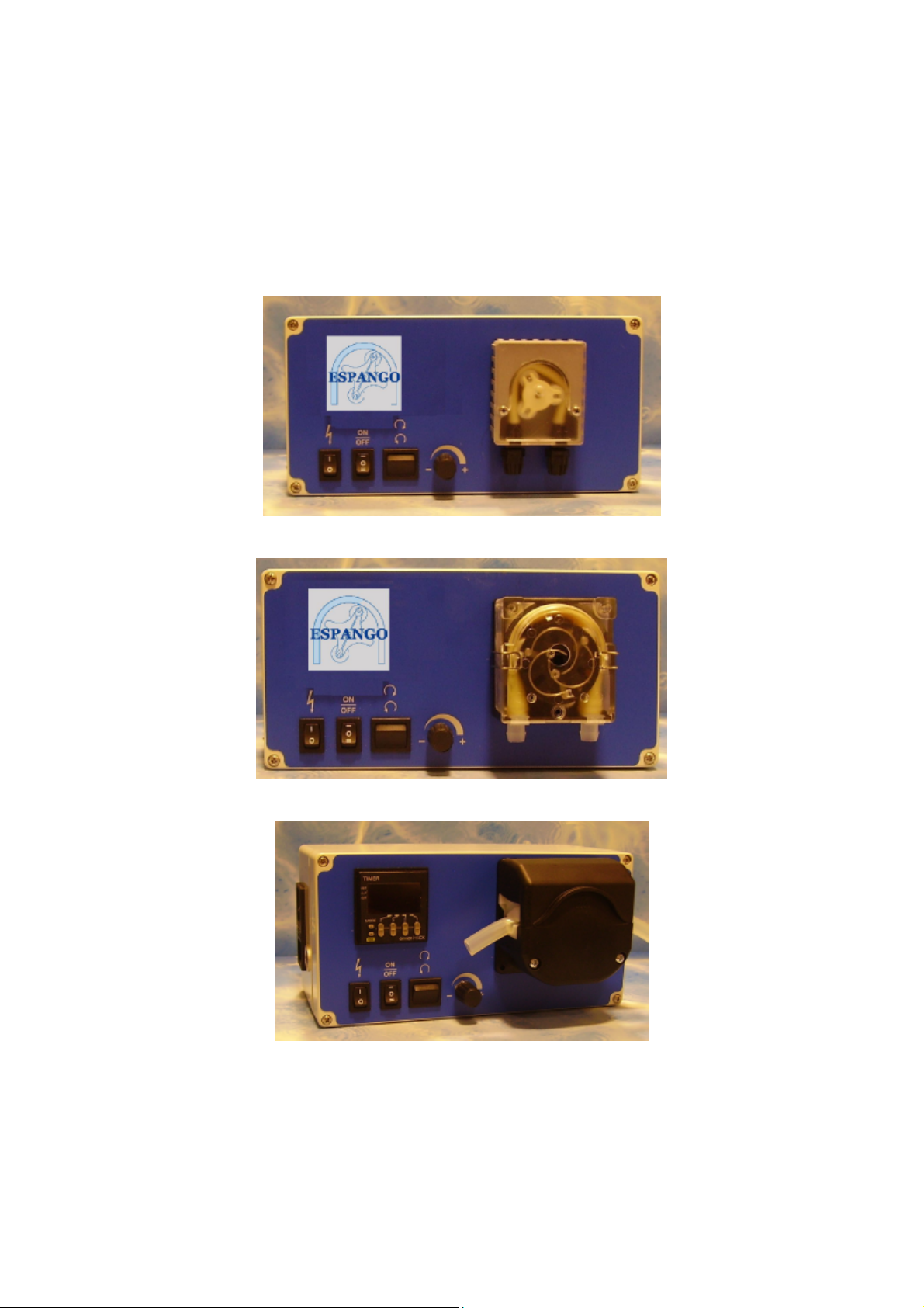
. The peristaltic pump IPL 10 is designed to be used in a laboratory or for industrial
purposes.
. The tube can be quickly replaced.
. The high rpm motor, coupled with a precise control system, guarantees an uniform
conveyance of the product.
. The speed of the pump IPL 10 is adjustable and it allows a precise control of the
pumped volumes.
. This pump is reversible. The rotation can be freely chosen. Even if the pump can run in
both rotation directions, it is better to use the “clockwise” one.
1.2 SAFETY
The safety –respect for people, environment and materials –mostly depends on the
behaviour of the employees who use the pump.
Please, carefully read this manual before starting to work with the pump. The respect of
our instructions will avoid errors which could be dangerous, especially concerning the
health and the environment.
When using this pump, the operator has always to refer to the present manual.
It has always to be available to all the people charged to use this pump.
We recommend to keep a copy of the manual close to the pump.
For safety reasons the equipment has always to be used by a qualified staff.
Before switching the pump on, please verify that the cable and the plug are not damaged;
in case they are, don’t connect the pump to the mains.
The voltage of the pump has always to be the same of the mains voltage.
Whatever action on the electric components has to be executed by qualified staff and the
pump has to be under security conditions (switched off, cable unplugged).
Only original parts and accessories must be used. We strongly discourage the employment
of not original spare parts, which can bring to unknown risks.
The characteristics and the safety of the pump can be granted only if all the required
controls, the maintenance and the repairs are executed by our authorized staff.
The manufacturer assumes no responsibility in case repairs are not executed by his
Technical Service or if not original parts or accessories should be used.
The manufacturer assumes no responsibility in case of misuse of the pump.

Manuale_IPL10_ENG_R0.doc
5
2. SETTING
2.1 POSITIONING
Handle the pump with care, avoiding shots. Never pick up the pump by its head or by the
cable. The pumps doesn’t have to be installed in a excessively dusty place.
Place the IPL 10 pump on a solid and non-flammable surface and be sure that it is firmly
supported.
The pump has to be protected from direct sunlight (UV radiation).
2.2 ELECTRICAL CONNECTION
The pump has a flexible cable.
Please use the plug to connect and disconnect the pump from the mains.
Before switching the pump on, verify that the cable and the plug are not damaged; in case
they are, do not connect the pump to the mains.
The voltage of the pump has to be the same of the mains one.

Manuale_IPL10_ENG_R0.doc
6
3. DESCRIPTION
3.1 PUMPING HEAD
The IPL 10 pumps can be provided with the following pumping head models:
IPL 10/24: head IPS24 -2 or 3 rollers (see photo)
IPL 10/30: head IPS30 -3 or 6 rollers (see photo)
IPL 10/100: head IPS100 -3 or 6 rollers (see photo)
IPL 10/24: head IPS24 IPL 10/30: head IPS30
Components identification: Components identification
:
1. fastening screws 1. closing spring
2. transparent case 2. transparent case
3. roller rotor 3. roller rotor
4. tube 4. tube
5. plastic fittings 5. plastic hooks
IPL 10/100: head IPS100
Components identification:
1. moving part
2. roller rotor
3. fixed part
On request and for special applications different pumping heads models can be used. In
this case, make reference to the technical indications given by our technical dept.
12345
8
6
9
7
3.2 CONTROL PANEL
1. Operation light (optional foot switch)
2. Start/stop button
3. Forward direction selection
4. Speed control potentiometer
5. Pumping head
6. Power pack: cable connection, switch, safety fuse
7. Cable output of the exterior foot switch (optional)
8. On/off timer (optional)
9. Switch on timer button (optional)

Manuale_IPL10_ENG_R0.doc
7
4. FUNCTIONING
4.1 TUBE INSERTION
THE PUMP MUST BE SWITCHED OFF!
PUMPING HEAD IPS24
1. Unscrew both fastening screws (1)
2. Remove the old tube (4)
3. Lay the tube in the pumping head, eventually slightly turning the roller rotor (3) to facilitate the
handle, hooking it to the case by mean of its plastic fittings (5).
4. Introduce the transparent cover again (2)
5. Fix the two screws firmly blocking all.
PUMPING HEAD IPS30
1. Open the two springs (1) placed on the sides of the case
2. Withdraw the part of the transparent moving-head (2) slightly turning it forward/down
3. Withdraw the old tube (4)
4a. For tubes with plastic fittings: lay the tube in the pumping head hooking it to the
case by mean of its plastic fittings (5)
4b. For bushings without hooks: lay the tube in the pumping head, keeping it in slight
tension at its end, introduce the supplied plastic rider, block the tube and keep it in
slight tension.
5. Insert the part of the moving-head again (2) starting from the side closer to the tube
exit. For the bushings version please remember to always keep the tube in slight tension.
6. Hook the two metal springs (1) to the case firmly blocking all.
PUMPING HEAD IPS100
1. Open the upper mobile part of the head (1) gently pulling it upward
2. Withdraw the old tube
3. Lay the new tube on the roller rotor (2) inside the moving-head, keeping it in slight tension at its
ends
4. Still keeping the tube in slight tension, close the upper part of the moving-head until you hear the
coupling click.
Now the pump is ready for use.
IMPORTANT NOTE: we guarantee its correct functioning only with tubes supplied and approved by us for
quality and measures. NEVER USE TUBES WHICH QUALITY IS NOT SPECIFIC FOR PERISTALITC
PUMPS.
4.2 FUNCTIONING SUGGESTIONS
•In order to avoid too high pressure, suction and delivery tubes have to be as short as possible. Prevent
bottlenecks and limit curves in rigid tubes.
•Employ big diameter tubes at low speed for a longer life tube.
•Employ small diameter tubes at highest possible speed for a better precision.
•When using viscous liquids proceed at low speeds. A high wall thickness tube has a better spring back
and it increases the suction capacity.
•If the chemical resistance of the tube in respect of the product to be pumped is unknown, a practical
test is recommended: weigh a piece of tube (3/4 cm) and soak it in the liquid for at least 24 hours.
Then visually control that the tube is not deformed and weigh it again; a variation of 10% of the weight
is acceptable. Afterwards, test the tube at the normal functioning conditions.

Manuale_IPL10_ENG_R0.doc
8
4.3 FUNCTIONING WITH TIMER (OPTIONAL VERSION)
1 2 3
Timer 1 secondo Timer 0,01 secondo
1 2 3 4
4.3.1 VERSION WITH 1” TIMER
. Press the key 1. “PROG” on the front to activate the programming of the ignition time
. Scan with the key PROG the functionality hours/minutes/seconds. Use the keys 2. “+” /
3. “-“ to modify the set value. Press again the key PROG to save the set value.
4.3.2 VERSION WITH 0.01” TIMER
. Press the key 1 to activate the programming of the ignition time
. Scan with the key 1 the functionality hours/minutes/seconds/tenths/centimes. The value
to be set will blink, use the keys 2 and 3 to increase or decrease the set value –press the
key 1 to move on the following value to be modified, until the end of the values.
How to activate the pump
-select on the front from the key no. 1 the position I or II
-on the position I the timer will be activated by the pulse of the pedal
-press the pedal ONCE or press the key 3. “START” on the control panel
The pump will work for the selected uptime and will stop at its expiry, releasing a beep.
The pump is now waiting for a new input to run again.
In order to “PAUSE” the pump DURING operation press again the pedal or the key
“START”.
Press again the pedal of the key “START” in order to restart the pump. The pump will work
for the remaining time indicated on the viewer.
It is possible to use the pump with timer also manually in two different modalities:
1) Continuous ignition: use the button no. 2 on the front, position ON. The pump will
run in continuous.
2) Power pulse: set the key no. 2 on the position OFF and the key no. 1 on the position
II; the pump will start with the pedal pressure and will stop at its release.

Manuale_IPL10_ENG_R0.doc
9
4.4 FUNCTIONING PROBLEMS
PROBLEM POSSIBLE CAUSE CORRECTIVE ACTION
1.The pump doesn’t a. the cable is not connected connect the cable
start
b. burnt/defective fuse change the fuse
c. the rotor is blocked due to assemble correctly
wrong assembly
2. the tube is mashed Wrong tube dimensions or the Use the appropriate tube or
and the range is reduced tube is worn replace it
3. The range of the pump a. the tube material is not Use the tube suitable for the
is incorrect compatible with the liquid product
b. dirty rolls Disassemble the pumping
head and clean it
c. wrong tube dimensions Use the appropriate tube
d. The pumped product is Use the appropriate tube
very viscous
4. The pumps stops There was an overload andSwitch the pump off and
during work the fuse is burnt solve the overload cause, then
change the fuse
Note: security fuses are placed in the power pack at the side of the pump
4.5 SWITCH OFF
Switch off the pump setting the switch on the position OFF.
Disconnect the cable from the mains.
Should the pump be kept inactive for a long period (days or weeks), remove the tube from
the pumping head.
If you don’t remove the compression, the tube could permanently remain deformed with a
consequent reduction of its performances and endurance.

Manuale_IPL10_ENG_R0.doc
10
5MAINTENANCE
The performances of the IPL 10 pump can be granted only if all the requested controls,
the extraordinary maintenance and the repairs are made by our authorized staff.
5.1 CLEANING
Use a water and delicate soap solution, with a smooth cloth, without abrasive to clean the
surfaces and the control commands. Avoid to use degreasing or abrasive products, because
they could irreversibly damage the surfaces.
Should the pump become dirty because of chemical products, etc., it will have to be
immediately cleaned in order to avoid their hardening.
Never pour a liquid on the pump during the running or the cleaning!
It is warmly recommended to proceed to an accurate cleaning of the pumping head after a
long running period. Residual particles coming from the normal wear of the tube could
adhere to the rollers, compromising their precise function.
Product residuals have to be regularly removed from the suction and delivery fittings, so
that a correct flow of the product is assured, avoiding bottlenecks.
The motor module and the head bearings do not need any maintenance. Never lubricate
them!
5.2 DISINFECTION/DECONTAMINATION
The plastic case can be decontaminated in case of organic contamination, treating it
externally with a disinfectant solution.
As far as disinfection is concerned, you have to act according to the current legislation.
Contact the manufacturer before using cleaning and disinfecting methods which are
different from the ones indicated in the present manual, because you could damage the
pump.

Manuale_IPL10_ENG_R0.doc
11
6. TECHNICAL SPECIFICATIONS
CHARACTERISTICS Measurement units
Case dimensions, net of pumping head
(width x height x length) mm 120 x 120 x 240
Case dimensions, pumping head included
IPS24 (width x height x length) mm 146 x 120 x 240
IPS30 (width x height x length) mm 166 x 120 x 240
IPS100 (width x height x length) mm 175 x 120 x 240
Weight kg 1.5
230 Volt version
Power V/Hz 230 Volt/ 50/60 Hz
Whead IPS24: 10 Watt
head IPS30: 30 Watt
head IPS100: 50 Watt
Fuse A / V head IPS24: 1 x Fuse 1.5 A /
250 V –delayed
IPS30: 1 x Fuse 1.5 A /
250 V –delayed
head IPS100: 1 x Fuse 2.0 A /
250 V –delayed
24 Volt AC/DC version
Power / Fuse V24 Volt AC/DC
see 230 Volt version
This manual suits for next models
3
Table of contents
Other ESPANGO Water Pump manuals
Popular Water Pump manuals by other brands

Seastar Solutions
Seastar Solutions HH4311 installation instructions

sauermann
sauermann Si-83 Series manual

Oase
Oase Neptun 1600 operating instructions

Monarch Industries
Monarch Industries ACT-SD Series owner's manual

GORMAN-RUPP PUMPS
GORMAN-RUPP PUMPS SF4E Installation, operation, and maintenance manual with parts list

Pentair
Pentair STA-RITE D Series owner's manual