Espi Voltar 2.0 User manual
USER’S MANUAL
™

ESPi VOLTAR 2.0 SOLAR UPS
____________________________________________________________________________________
Technical Specifications 2
TABLE OF CONTENTS
PREFACE……………………………………………………………………………………….1
TABLE OF CONTENTS……………………………………………………………………….2
RELEASES TO THIS TECHNICAL DOCUMENTATION………………………………….3
PUBLICATION………………………………………………………………………………….4
USING THIS TECHNICAL PRACTICE………………………………………………………4
INSPECTING SHIPMENT……………………………………………………………………..4
PRODUCT SPECIFICATIONS……………………………………………………………...5-6
SAFETY PRECAUTIONS……………………………………………………………………...7
QUARTER-TURN LOCKING DOOR LATCHES……………………………………………8
ENCLOSURE OVERVIEW…………………………………………………………………….9
WIRING INSTRUCTIONS………………………………………………………………...10-11
UPS FACEPLATE…………………………………………………………………………12-13
LCD SCREEN OPERATION……………………………………………………………..14-17
ENCLOSURE MEASUREMENTS……………………………………………………….18-19
INSTALLATION PROCEDURE…………….…………………………...…………………..20
CLEARANCE REQUIREMENTS……………………………………………………………21
CABINET GROUNDING INFORMATION.…………………………………………………22
GROUNDING DIAGRAM & PROCEDURE.……………………………………………….23
ALARM CONNECTORS……………………………………………………………………..24
DETERMINING PROPER SOLAR ANGLE………………………………………………..25
SOLAR PANEL BRACKET ASSEMBLY- POLE MOUNT…………………………...26-29
APPENDIX A…………………………………………………………………………………..30
TECHNICAL SUPPORT……………………………………………………………………30
ORDERING PROCEDURE………………………………………………………………...30
APPENDIX B…………………………………………………………………………………..31
CORPORATE POLICY……………………………………………………………………..31
RMA PROCEDURE…………………………………………………………………………31
APPENDIX C…………………………………………………………………………………..32
ESPI STANDARD TERMS AND CONDITIONS……………………………………………32

ESPi VOLTAR 2.0 SOLAR UPS
____________________________________________________________________________________
Technical Specifications 3
TECHNICAL DOCUMENTATION
Thank you for purchasing the ESPi VOLTAR 2.0 Solar UPS. At ESPi, we are proud of
the quality products we innovate and manufacture and look forward to serving you as
our customer. Please review all sections of this document before the installation and
operation of the VOLTAR 2.0.
This document pertains to the VOLTAR 2.0 Solar UPS and its family of products.
Applicable Model Numbers:
VOLTAR 2.0
- V2-20A-150W-12V-1D
- V2-20A-150W-12V-2D
- V2-20A-150W-12V-1N
- V2-20A-150W-12V-2N
- V2-20A-150W-48V-1D
- V2-20A-150W-48V-2D
- V2-20A-150W-48V-1N
- V2-20A-150W-48V-2N
Contact Information:
- Email sales@espicorp.com for sales related questions or requests.
- Email info@espicorp.com for technical product support.
- Telephone: (877) 799-3774

ESPi VOLTAR 2.0 SOLAR UPS
____________________________________________________________________________________
Technical Specifications 4
PUBLICATION
This publication provides a description of ESPi’s VOLTAR 2.0 Solar UPS. In this
publication, an overview of the product, mechanical descriptions, installation
instructions, safety guidelines and grounding instructions are included.
USING THIS TECHNICAL PRACTICE
Before using this document, please review the statements below.
1. The differences in models of the VOLTAR 2.0 family of solar UPS products are
defined by the attributes within the model number. Definitions of the attributes are
described below.
•V2-20A-150W-XXV-XX
•V2 = VOLTAR 2.0 Product Family
•20A = Max Charging Rate
•150W = Max Wattage
•XXV = 12 Volt or 48 Volt Model
•XX = 1D, 2D, 1N, 2N – Number of Batteries
2. Two types of messages appear throughout this manual, identified by the
following icons:
Note - Indicates special conditions.
Caution - Indicates possibility of personal injury or equipment damage.
INSPECTING SHIPMENT
Upon receipt of the equipment:
- Inspect the shipping container(s) and note any signs of damage. Next, unpack the
container(s) and carefully inspect for damage to the contents. If the equipment has
been damaged in transit, immediately report the extent of damage to the transportation
company and to ESPi. Order replacement equipment if necessary.
- Check the packing list to assure complete and accurate shipment of all listed items. If
the shipment is short or irregular, contact ESPi as described in the warranty. If the
equipment must be stored for a prolonged period, do so in the equipment’s original
container. For any returned equipment please use the original packaging if available.

ESPi VOLTAR 2.0 SOLAR UPS
____________________________________________________________________________________
Technical Specifications 5
PRODUCT SPECIFICATIONS
The VOLTAR 2.0 Solar UPS is designed to provide instant, continuous power for a wide
range of applications. For additional information and specifications, reference the
product overview information listed below.
Enclosure
•Dimensions: 35” tall x 16” wide x 11.5” deep
•Constructed for superior strength using galvanized steel
•Powder coat painted for corrosion resistance
•Meets NEMA 4 standards
•(2) Quarter-turn pad-lockable latching systems
•Wind guard stop
•Adjustable shelving for increased battery capacity
•Weight w/o Batteries: 70 lbs.
Input Power Sources
•(2) Independent input sources
•24 - 60 Volts Max and less than 10 Amps
•Reverse polarity protection
•Maximum Power Point Tracking (MPPT)
User Interface
•LCD Screen
•(3) Push Buttons – Back, Next, Select
•(3) LED indicator gauges: Battery Level and Equipment Status
Battery Charging
•20 Amp Charger
•Advanced 4 stage charger with Multi Point Power Tracking (MPPT)
•Temperature Compensated Charging
•Operating Temperature -20°C to +105°C
Batteries
•Multiple battery configurations available
•123Ah or 170Ah Solar Batteries
•123Ah Battery Weight: 83 lbs.each
•170Ah Battery Weight: 130 lbs. each
•12V Batteries Only
•Lead-Acid (LA), Sealed-Lead-Acid (SLA), Absorbed Glass Mat (AGM)
•10-Year Design Life
•3-Year Limited Warranty

ESPi VOLTAR 2.0 SOLAR UPS
____________________________________________________________________________________
Technical Specifications 6
Solar Panel
•Mono-Crystalline .
•Bi-Facial Panel
•40.6 Volts
•370 Watts
•77.48" x 38.97"
•35-Year Limited Warranty
Output
•12V, 24V, 36V, 48V, Other (Based on model #)
•150 Watts Max
•30 Watts Continuous
Alarm Outputs
•Dry-Contact RJ-45 termination. Four isolated contact-closure alarm outputs: No
Battery, On Battery, Low Battery and Battery Fail

ESPi VOLTAR 2.0 SOLAR UPS
____________________________________________________________________________________
Technical Specifications 7
SAFETY PRECAUTIONS
•USE COMMON SENSE!
•Only qualified personnel should service this equipment
•The battery contains hazardous currents and may present a burn hazard if
damaged, shorted, or installed improperly.
•The following precautions should be followed to insure your safety
oRemove watches, rings, or other metallic objects.
oWear protective clothing and eye protection when working with batteries.
oAlways carry a water supply to wash eyes or skin in the event of exposure
to battery electrolyte.
oUse of tools with insulated handles is required.
oDo not disassemble the unit. No user serviceable parts are inside except
the batteries and fuse.
oKeep liquid and foreign objects from getting inside of the unit.
oAvoid operating unit in excessive humidity or near water.
oDo not operate near gas or fire.
oInspect unit for leaking substance. If substance is leaking, do not use
product.
oServicing this equipment may require working with protective covers
removed and utility power connected. Use extreme caution during these
procedures.
oCheck that power cord, plugs, and output terminals are in good working
order.
oBATTERY WARNINGS – Danger of explosion if battery is incorrectly
connected. Use only approved replacement batteries.
oWorn out or damaged batteries are considered environmentally unsafe.
ALWAYS recycle used batteries in accordance with all federal, state, and
local regulations. This is your planet too!
oAny gel or liquid emissions from a VRLA battery contain sulfuric acid,
which is harmful to the skin and eyes.
oBatteries can produce explosive gases. Avoid all open flames and sparks.
oBatteries contain or emit chemicals known to the State of California to
cause cancer and birth defects or other reproductive harm. Battery post
terminals contain lead and lead compounds. Wash hands after handling.
(California Proposition 65)
oWear protective clothing and eye protection when installing, maintaining,
servicing, or replacing batteries.
oIf battery emissions contact the skin or eyes, immediately wash area with
water. Report chemical spills and seek medical attention if necessary.
oAlways replace batteries with new batteries of identical type and rating.
oA battery showing signs of cracking, leaking, or swelling should be
replaced immediately with an approved battery.
ESPi VOLTAR 2.0 SOLAR UPS
____________________________________________________________________________________
Technical Specifications 8
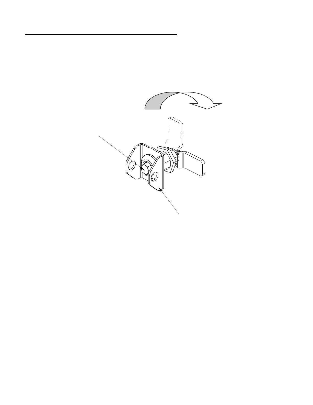
QUARTER TURN LOCKING DOOR LATCHES
The cabinet door is equipped with (2) quarter-turn pad-lockable latches. The latch is
secured by turning the 7/16" hex security bolt one quarter turn clockwise until the stop is
reached. A convenient security locking hasp is factory installed to allow for a standard
Master lock padlock (or equivalent) to be installed. With a padlock inserted, the security
bolt cannot be accessed. Thus, protecting the cabinet from undesired intrusions.
Figure A – Quarter Turn Locking Door Latch
Padlock Security Hasp
Unloc
Lock
7/16" Hex Security Bolt

ESPi VOLTAR 2.0 SOLAR UPS
____________________________________________________________________________________
Technical Specifications 9
ENCLOSURE OVERVIEW
Figure B – Front View of Enclosure
Door is not shown. Image is for reference only.
---------------------------------------------------------------------------------------------------------------------
------
ESPi VOLTAR 2.0 SOLAR UPS
____________________________________________________________________________________
Technical Specifications 10
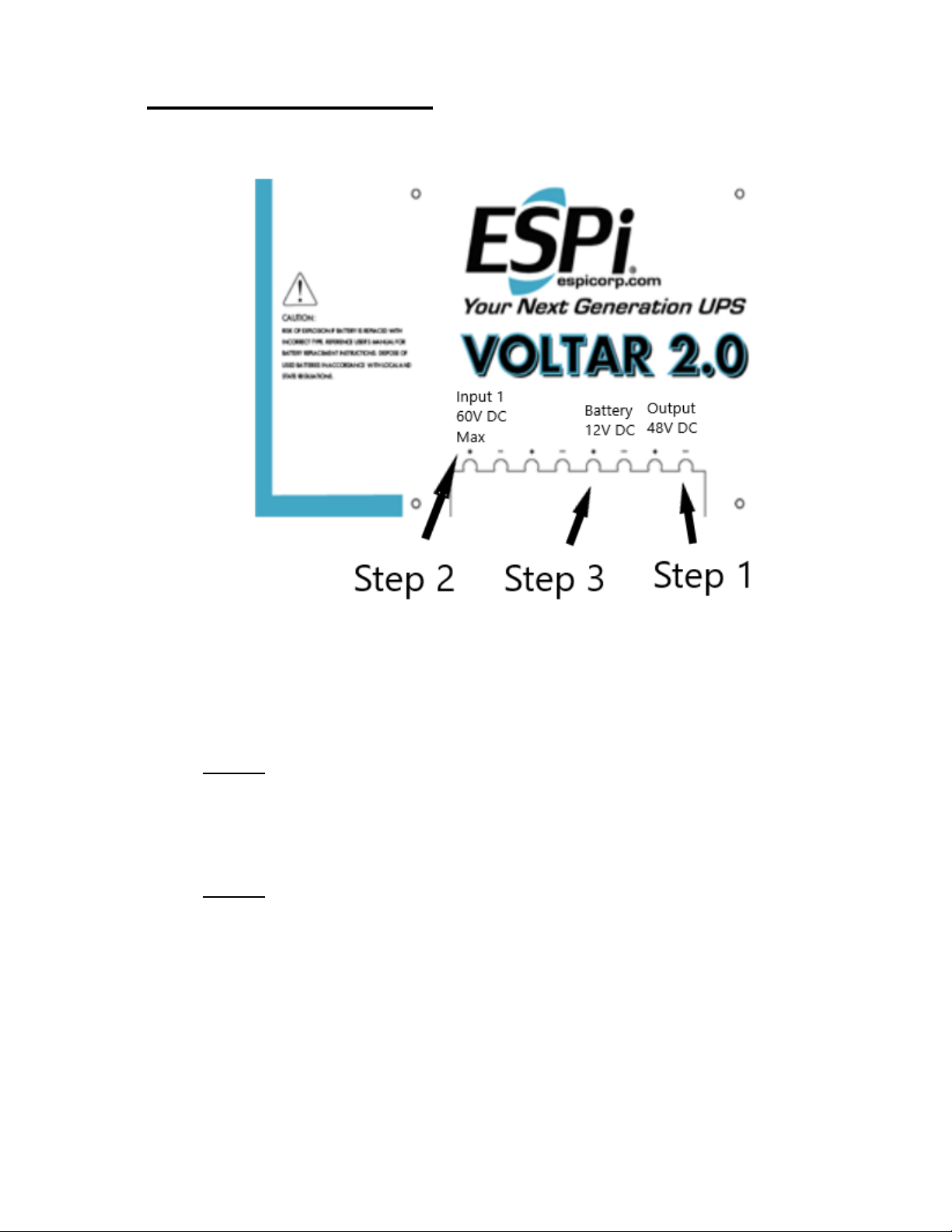
WIRING INSTRUCTIONS
Figure C – Wiring Instructions
To avoid causing electrical damage to the VOLTAR 2.0 circuit board, please use the
following steps when wiring.
Step 1:
Connect all wires from the VOLTAR 2.0 Output terminal to the load you are
powering. If you have multiple VOLTAR 2.0 units, this should be done for each
unit.
Step 2:
There is 20 feet of red and black photovoltaic wire routed through the enclosure
and connected to the Input 1 terminal. If you do not need to use all 20 feet of
wire, you can shorten to the desired length using the following process.
Disconnect the solar panel to measure the length of wire needed to reach from
the solar panel, through the bottom of the enclosure and up to the Input 1
terminal. Next, loosen the Input 1 terminal screws and cut the red and black
photovoltaic wire to this length. Once this is complete, insert the red and black
photovoltaic wires into the Input 1 terminal and tighten.

ESPi VOLTAR 2.0 SOLAR UPS
____________________________________________________________________________________
Technical Specifications 11
(Note: 20 feet of photovoltaic wire has been provided to you. If you need more
than 20’ of wire it may be sourced locally or contact ESPi for more information.)
Step 3:
Attach the red (Positive) and black (Negative) battery leads to the 12-volt battery.
After attaching the cables, various LED lights on the faceplate will light up.
Further details regarding the LED gauges are provided on the following pages.
ESPi VOLTAR 2.0 SOLAR UPS
____________________________________________________________________________________
Technical Specifications 12
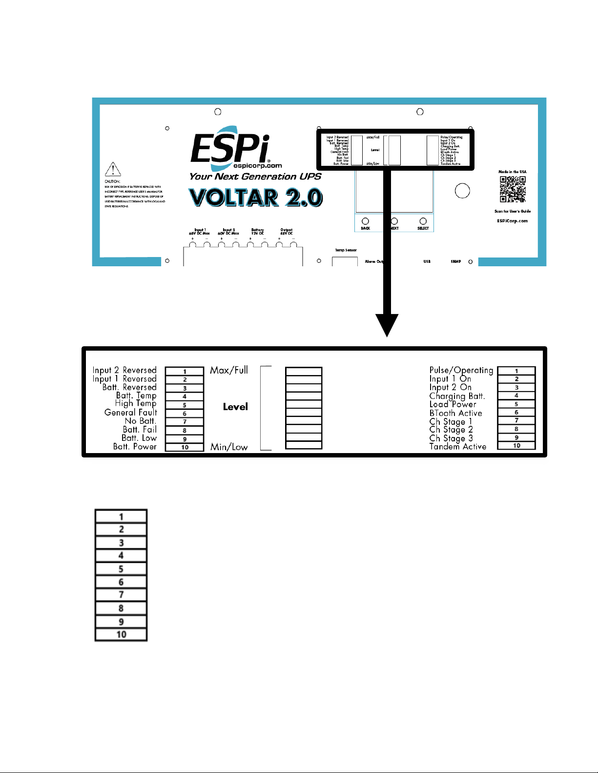
Figure D – UPS Faceplate
LEFT CENTER RIGHT
LED GAUGE - LEFT
1. Input 2 Reversed: Polarity reversed on Input 2
2. Input 1 Reversed: Polarity reversed on Input 1
3. Batt. Reversed: Polarity reversed on battery
4. Batt. Temp: Battery Temperature -20°C to 60°C
5. High Temp: PCB Temperature
6. General Fault: Not applicable
7. No Batt.: Battery is not installed
8. Batt. Fail: Battery not working correctly
9. Batt. Low: Battery is low
10. Batt. Power: Running on Battery Power (Only applicable if input source is set to DC
Power Supply)

ESPi VOLTAR 2.0 SOLAR UPS
____________________________________________________________________________________
Technical Specifications 13
LED GAUGE – CENTER
LED GAUGES – RIGHT
1. Pulse/Operating: Unit is currently in operation
2. Input 1 On: Input 1 hooked up and in operation
3. Input 2 On: Input 2 hooked up and in operation
4. Charging Batt.: Battery charging
5. Load Power: On if load power is powered on
6. BTooth Active: Bluetooth on and in operation
7. Ch. Stage 1: Constant Current
8. Ch. Stage 2: Constant Voltage
9. Ch. Stage 3: Float Voltage
10. Tandem Active: VOLTAR 2.0 units paired and in operation

ESPi VOLTAR 2.0 SOLAR UPS
____________________________________________________________________________________
Technical Specifications 14
LCD SCREEN OPERATION
Once the wiring is complete on the VOLTAR 2.0, allow for up to 10 minutes before
charging current will start going to the battery. The VOLTAR 2.0 is designed to look for
input voltage above 24VDC before it will start the battery charge sequence. After the 5-
10 minute sequence is complete, and if the input voltage is above 24 Volts, you should
see charging current being sent to the battery. (Note: The battery must less than 14.2V
to activate charging)
Home Screen
If you are using a solar panel to power the VOLTAR 2.0 unit, it must be connected to
the Input 1 terminal. Input 2 is configured for a DC power supply (Generator Kit) only.
The Generator Kit is only needed when poor solar conditions are present for an
extended period of time and the battery must be charged using an alternative
method.
Date
Battery Voltage
Charge amps to the battery
Circuit board temp °C
Time
Firmware Version
Product

ESPi VOLTAR 2.0 SOLAR UPS
____________________________________________________________________________________
Technical Specifications 15
After the startup sequence, on the Home Screen the charge amps to the battery should
begin to rise. When switching to the PRIMARY INPUT screen, the amount of power
being produced by the solar panel is provided on the screen. This screen displays the
solar panel volts, amps and watts. Watts is calculated as Volts x Amps.
.
The BATTERY screen provides details on the battery. Once the battery begins
charging, the battery voltage will start to rise. The battery level, along with the power
being provided by the solar panel, determines the charge rate of the battery. The
VOLTAR 2.0 unit also employs temperature compensated charging. The temperature of
the battery is displayed on the upper right-hand corner of the screen. Note that the
temperature displayed is in degrees Celsius.
Input voltage from Input 1 or 2
Input Volts DC
Input Amps
Input Watts
Battery Temp °C
Battery Volts
Amps to Battery
Watts to Battery

ESPi VOLTAR 2.0 SOLAR UPS
____________________________________________________________________________________
Technical Specifications 16
The LOAD OUTPUT screen displays the voltage, amperage and watts going to the
equipment being powered by the VOLTAR 2.0. Note that the VOLTAR 2.0 has a max
output of 150 watts, but this is only for short durations during startup. Once the load has
gone through a reboot or startup phase, typically the power consumed by most
equipment will only vary slightly.
Volts to load
Amps to load
Watts to load

ESPi VOLTAR 2.0 SOLAR UPS
____________________________________________________________________________________
Technical Specifications 17
The VOLTAR 2.0 is equipped with a 4-stage charger. Each stage is as follows:
Stage 0:Trickle charging
Stage 1:Constant Current
Stage 2:Constant Voltage
Stage 3:Float Voltage
Charging Stage
Power Source for charging
the battery.
Solar Panel State
ESPi VOLTAR 2.0 SOLAR UPS
____________________________________________________________________________________
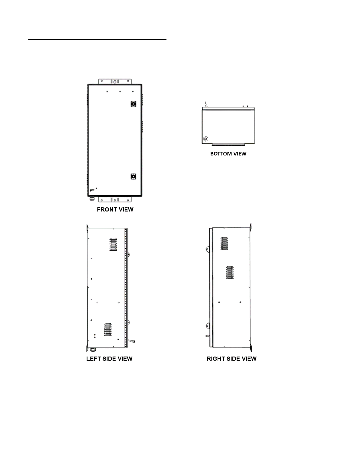
Technical Specifications 18
ENCLOSURE MEASUREMENTS
Figure E – Enclosure Overview

ESPi VOLTAR 2.0 SOLAR UPS
____________________________________________________________________________________
Technical Specifications 19
Figure F – Enclosure Overall Dimensions

ESPi VOLTAR 2.0 SOLAR UPS
____________________________________________________________________________________
Technical Specifications 20
INSTALLATION PROCEDURE
The installation of the unit must be performed by skilled technicians and electricians
familiar with electrical equipment. Do not allow unqualified personnel to handle, install,
or operate the equipment. Install this unit in a location away from gas, fire, and potential
sparks. The VOLTAR 2.0 series cabinet is shipped ready for equipment and battery
installation. The following pages will provide information on mounting, grounding
procedure, alarm connection guide, solar panel installation and more.
Figure G – Cabinet Mounting
This manual suits for next models
8
Table of contents
Other Espi Power Supply manuals

Popular Power Supply manuals by other brands

Akyga
Akyga AK-NU-03 user manual

Würth
Würth 0827 981 521 operating manual

Belden
Belden Hirschmann PC150/36V/48V-IP67 Description and operating instructions

EFOY
EFOY COMFORT80 installation guide

National Instruments
National Instruments PXIe-4135 CALIBRATION PROCEDURE

McPower
McPower Digi 30-3 Reference manual


 Installation sheet")


