OmniOn Power CPS6000 II Series User manual

Page 1
© 2023 OmniOn Power Inc. All rights reserved. CPS6000_Series II 2U_QSG Rev. 3.2
CPS6000 Power System
Models: CC109161163 23” Shelf, Rear AC input terminals, 5 power slots, Rear bulk output
CC109171575 Dual Shelf Kit
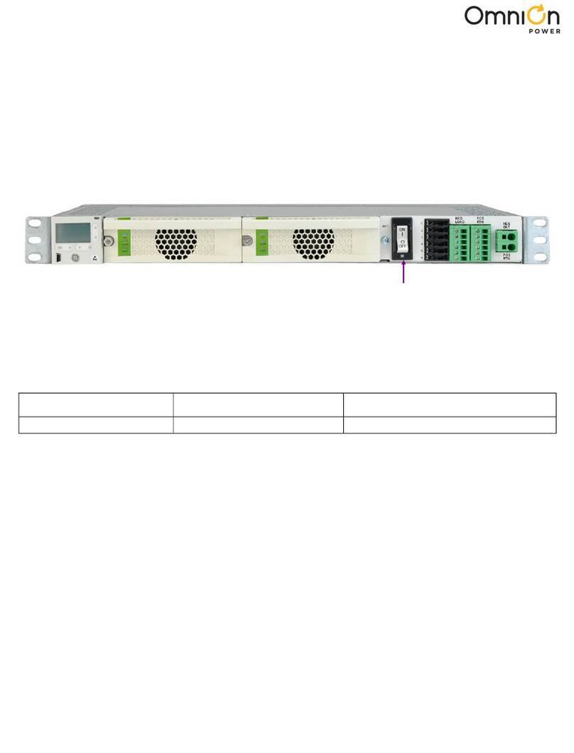
This CPS6000 power system is a 23” shelf equipped with a Pulsar Edge Controller.
Single shelf system Start with Step 1 on this page.
Two shelf system Start with Step A1 of the Two Shelf System Addendum on page 5.
Tools required:
Step 1 - Mount Shelf
Attach shelf to the frame using a minimum of four screws (two on each side) - 12-24 (provided).
Torque to 35 in-lb (4Nm) 5/16” socket.
Step 2 - Connect AC Inputs
This shelf is equipped with rear access terminal blocks and knockouts on the side and top for conduit ttings.
The AC feeds may be 110Vac or 208/220Vac, depending on the type of rectier used.
Each rectier can be fed from an individual circuit or one feed can power two or three rectiers.
Connect the appropriate size ac wiring to the AC terminal blocks.
Caution: Ensure ac power is OFF and use appropriate lock-out tag-out procedures before continuing with ac
connections.
Caution: When connecting to utility source, ensure all local and national wiring rules are being complied with.
Caution: When routing AC cables ensure cable does not come in contact with sharp or rough surfaces that may damage
insulation and cause a short circuit. Make sure cable does not come in contact with any pinch points such as doors.
QUICK START GUIDE
• Wire cutters and strippers • Sockets - 5/16”, 7/16, etc.
• Cable crimpers • Screwdrivers- Philips #1 and #2 Flat small
• Torque wrench - 0-65 in-lb (0-10Nm)
Use a pair of needle nose pliers to
remove the divider between the
individual rectier feeds when sharing
inputs.
Install a strap between the terminal
blocks. Secure the strap in position with
screws and torque to 10 inch lbs. Straps
and screws are provided.
Snap Loose
Plastic Divider
With Pliers

Page 2
© 2023 OmniOn Power Inc. All rights reserved. CPS6000_Series II 2U_QSG Rev. 3.2
Step 3 - Connect Chassis and DC Reference (CO) Grounds
Connections are on the rear.
• Lug Landing: #10 on 5/8-inch center (lugs not provided)
• 10 AWG recommended
1. Connect Chassis Ground - Torque to 30 in-lb (4 Nm)
2. Connect DC Reference Ground - Torque to 30 in-lb (4 Nm)
Step 4 - Connect DC Output
Connections are on the rear. The shelf provides unprotected bulk output to an external distribution panel.
1. Lug Landing: #10 on 5/8-inch center (lugs not provided)
2. Connect +Bulk and -Bulk cables - Torque to 30 in-lb (4 Nm)
Step 5 - Set Jumpers - LAN Port and Relay per Galaxy Pulsar Edge Controller Quick Start
Guide
1. Set Jumpers - LAN Port and Relay
Step 6 - Install Controller per Galaxy Pulsar Edge Controller Quick Start Guide
Step 7 - Install Signal and Communicaons Cables
Connectors are on front
See Information: Alarm Connections … for Details
1. J1 Alarms and Inputs - Connect to ofce alarms and signals.
2. J5 LAN - Connect to Ethernet network.
Step 8 - Install 1-Wire Baery Temp and Voltage Monitor per Galaxy Pulsar Edge Controller
Quick Start Guide - Oponal (not available in two shelf systems)
1. Connect 1 – Wire Battery Temp and Voltage Monitor to J2
Note: Some applications may rely on frame mounting
screws for chassis ground omitting the shelf
ground cable.
- Bulk load output
(unprotected)
Chassis Ground
+ Bulk load output
(unprotected)
DC Reference ground
If required
Step 2 - Connect AC Inputs (Connued)
Relay Jumpers

Page 3
© 2023 OmniOn Power Inc. All rights reserved. CPS6000_Series II 2U_QSG Rev. 3.2
Step 9 - Controller Connecons
Connectors are on front.
See Information: Alarm Connections … for Details
1. J1 Alarms and Inputs - Connect to ofce alarms and signals.
2. J2 LAN - Connect to Ethernet network (can also be used as a Craft Port when congured as a Server).
Step 6 - Recer Installaon
1. Unlatch the handle as shown above.
2. Firmly push the rectier into the rectier slot until the latch pops most of the way up.
3. Push the latch into the latched position.
NOTE: When installing a rectier in a powered system the ALM LED on the rectier will blink until
communication with the controller is established.
Local Port LAN
Ofce alarm connector. See
Information: Ofce Alarm
Connections.
J2 - see Information: Battery Temp TP Monitor
Craft USB Port
Press Latch/Handle
Release Button IN
Latch/Handle in
Latched Position
Latch/Handle
Springs Out Part
Way
Press Latch/Handle
Rotated All The Way
Down

Page 4
© 2023 OmniOn Power Inc. All rights reserved. CPS6000_Series II 2U_QSG Rev. 3.2
Informaon: Alarm Connecons
Ofce alarm connector (J1) is located on the left side of the shelf. It provides access to the alarm relay inputs and outputs.
Note the wire color and alarm descriptions in the attached table
Two Shelf System Addendum
Two shelf systems combine two identical shelves and install a controller into the top shelf. Top Shelf Signal connections,
Controller, Control Panel - Active Bottom Shelf Signal connections not used, Controller not installed, Control Panel -
Inactive (unpowered)
Pos Color Signal Factory Default
1BLK User Congurable Alarm
Input Door Open
2WUser Congurable Alarm
Input AMJ (Aux Major)
3R/BLK PTC Protected VBUS-/ABS NA
4OR Power Major Relay Return PMJ Return
5OR/BLK Power Minor Relay Return PMN Return
6R/WHT Relay 1 Return BOD/AC Fail
Return
7WHT/
BLK Relay 2 Return ACF Return
8BL/R Relay 3 and Relay 4 Return FAJ Return R3 & R4
9RUser Congurable Alarm
Input SPD Fail
10 GR User Congurable Alarm
Input
Air Conditioner
Fail
11 BL Relay 4 Unassigned
12 GR/BK Power Major Relay PMJ (Power Major)
13 BL/BK Power Minor Relay PMN (Power
Minor)
14 GR/WHT Relay 1 BOD/AC Fail
15 WHT/R Relay 2 ACF
16 OR/R Relay 3 FAJ
J1
1
9
16
8
Shelf to Shelf Signal Cable
Shelf Address ID
Jumpers (2)
1 2 3
Circuit
Board

Page 5
© 2023 OmniOn Power Inc. All rights reserved. CPS6000_Series II 2U_QSG Rev. 3.2
Step A1 - Set Shelf Address Jumpers on Boom Shelf
Set Shelf ID Jumpers (2) on bottom shelf as shown above.
Step A2 - Mount Shelves per main Step 1
Step A3 - Install Shelf to Shelf Signal Cable
Install cable between J2 on both shelves.
Step A3 - Proceed with installaon from main Step 2
Specications and Application
• Specications and ordering information are in the Slimline Power System Ordering
Brochure available at omnionpower.com
• External Surge Protective Device (SPD) is required on all AC inputs.
Equipment Safety is Approved in IEC 60664-1 Installation Category II environments.
• Equipment and subassembly ports: 1. are suitable for connection to intra-building or unexposed wiring or cabling;
2. can be connected to shielded intra-building cabling grounded at both ends.
• Grounding / Bonding Network – Connect to an Isolated Ground Plane (Isolated Bonding Network) or an
Integrated Ground Plane (Mesh-Bonding Network or Common Bonding Network).
• Installation Environment - Install in Network Telecommunication Facilities, OSP, or where NEC applies.
• Battery return may be either Isolated DC return (DC-I) or Common DC return (DC-C).
Reference Documents
These document s are available at omnionpower.com
Document Title
CPS6000_MAN CPS6000 Power Shelf Product Manual
Pulsar Edge_QSG Galaxy Pulsar Edge Controller Quick Start Guide
Pulsar Edge_MAN Pulsar Edge Controller Family Product Manual

Page 6
© 2023 OmniOn Power Inc. All rights reserved. CPS6000_Series II 2U_QSG Rev. 3.2
OmniOn Power Inc.
601 Shiloh Rd.
Plano, TX USA
omnionpower.com
We reserve the right to make technical changes or
modify the contents of this document without prior
notice. OmniOn Power does not accept any responsibility
for errors or lack of information in this document and
makes no warranty with respect to and assumes no
liability as a result of any use of information in this
document.
We reserve all rights in this document and in the subject
matter and illustrations contained therein. Any
reproduction, disclosure to third parties or utilization of
its contents – in whole or in parts – is forbidden without
prior written consent of OmniOn Power. This document
does not convey license to any patent or any intellectual
property right. Copyright© 2023 OmniOn Power Inc. All
rights reserved.
This manual suits for next models
2
Table of contents
Other OmniOn Power Power Supply manuals
Popular Power Supply manuals by other brands

NewMar
NewMar PM-24-80 Installation and operation manual

BRUEL & KJAER
BRUEL & KJAER 2804 Service instructions

Charles
Charles C-Power 93-PS2415 Installation instructions & owner's manual

HB-THERM
HB-THERM T24693 Assembly instructions

AUTLED
AUTLED NT-810-154 user manual

AUSTRALIAN MONITOR
AUSTRALIAN MONITOR AMIS PPA2 introduction

Husky
Husky Jump-Start System HSK020HD owner's manual

Basalte
Basalte PUCK installation manual

Toshiba
Toshiba TOSVERT VF-AS1 Series instruction manual

Mitsubishi Electric
Mitsubishi Electric PAC-SC51KUA installation manual

Crestron
Crestron CSA-PWS10S-HUB-ENET installation guide

Elenco Electronics
Elenco Electronics XP-605 instruction manual