S8JC-Z
4
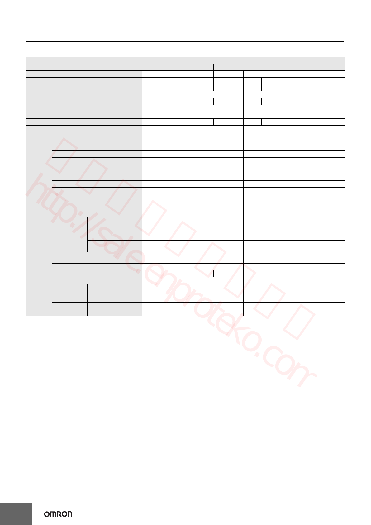
Ratings, Characteristics, and Functions
15-/35-W Models
Note: 1. Unless otherwise specified, all parameters are measured with a 230-VAC input, at the rated load, and at an ambient temperature of 25°C.
2. Ripple and noise are measured at a bandwidth of 20 MHz.
3. Refer to the dimensional diagrams for details on DIN Rail-mounting Models (excluding terminal blocks and DIN Rail products).
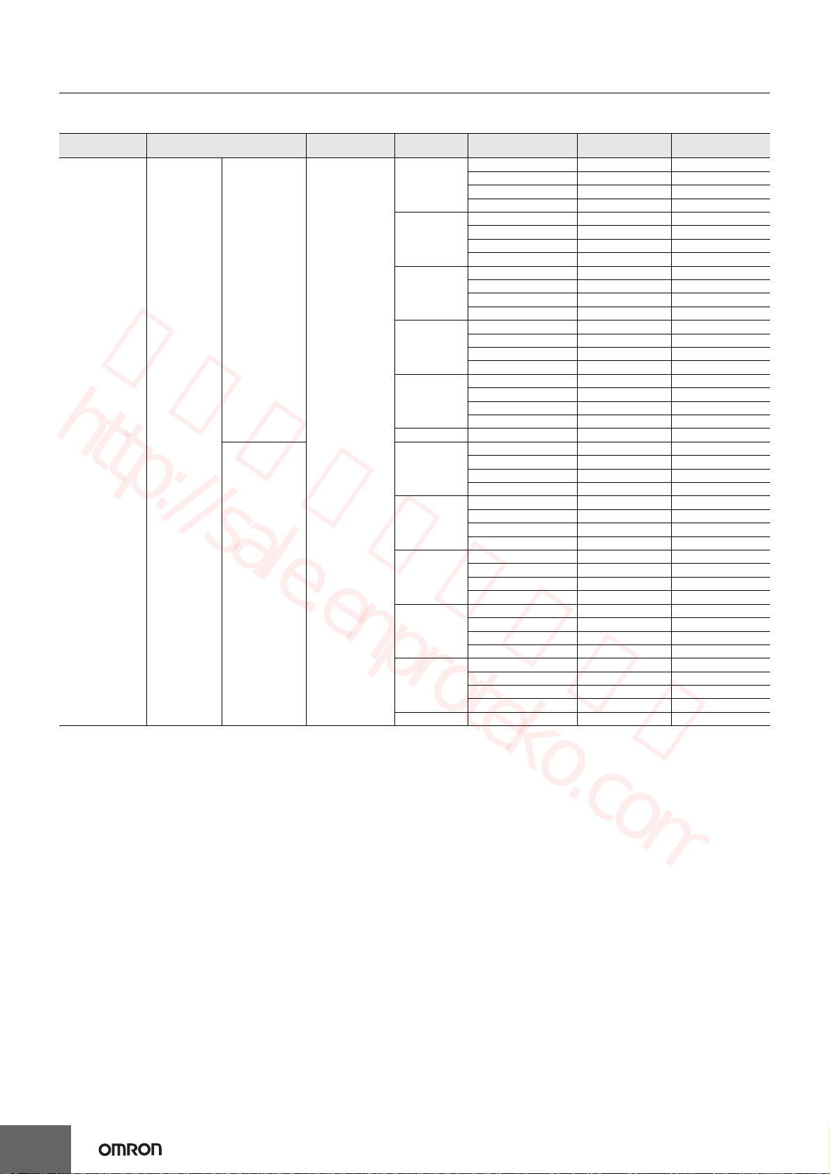
Power ratings 15 W 35 W
Item Series name S8JC-Z S8JC-ZS S8JC-Z S8JC-ZS
Certification --- CE(EN50178) --- CE(EN50178)
Output
Output voltage (VDC) 5 V 12 V 24 V 48 V 24 V 5 V 12 V 24 V 48 V 24 V
Output current 3.0 A 1.3 A 0.7 A 0.35 A 0.7 A 7.0 A 3.0 A 1.5 A 0.75 A 1.5 A
Voltage adjustment range (typical) −10% to 10% −10% to 10%
Ripple (typical) 100 mV 200 mV 50 mV 100 mV 150 mV 200 mV 50 mV
Startup time (typical) 300 ms 300 ms
Hold time (typical) 50 ms 30 ms 40 ms
Efficiency (typical) 74% 80% 86% 81% 75% 82% 84% 88% 83%
Input
Voltage 200 to 240 VAC (185 to 264 VAC) 200 to 240 VAC (185 to 264 VAC)
Frequency 50/60 Hz
(47 to 63 Hz) 50/60 Hz (47 to 64 Hz) 50/60 Hz (47 to 64 Hz)
Current (typical) 0.22 A 0.5 A
Leakage current 1 mA max. 1 mA max.
Inrush current (for a cold start at 25°C)
(typical) 40 A 40 A
Additional
functions
Overload protection 105% of rated load current, voltage drop, intermittent,
automatic reset
105% of rated load current, voltage drop, intermittent,
automatic reset
Overvoltage protection Yes Yes
Parallel operation No No
Series operation No No
Other
Ambient operating temperature
*Refer to the derating curve in Engineering
Data
S8JC-Z: *−10°C to 60°C
S8JC-ZS: *−20°C to 70°C
S8JC-Z: *−10°C to 60°C
S8JC-ZS: *−20°C to 70°C
Dielectric
strength
(detection
current: 20 mA)
Between all inputs and
outputs
S8JC-Z: 1.5 kVAC for 1 min.
S8JC-ZS: 3 kVAC for 1 min.
S8JC-Z: 1.5 kVAC for 1 min.
S8JC-ZS: 3 kVAC for 1 min.
Between all inputs and PE
terminals
S8JC-Z: 1.5 kVAC for 1 min.
S8JC-ZS: 2 kVAC for 1 min.
S8JC-Z: 1.5 kVAC for 1 min.
S8JC-ZS: 2 kVAC for 1 min.
Between all outputs and
PE terminals
S8JC-Z: 0.5 kVAC for 1 min.
S8JC-ZS: 1 kVAC for 1 min.
S8JC-Z: 0.5 kVAC for 1 min.
S8JC-ZS: 1 kVAC for 1 min.
Vibration resistance 10 to 55 Hz, 0.26-mm single amplitude for 2h each in X,
Y, and Z directions
10 to 55 Hz, 0.26-mm single amplitude for 2h each in X,
Y, and Z directions
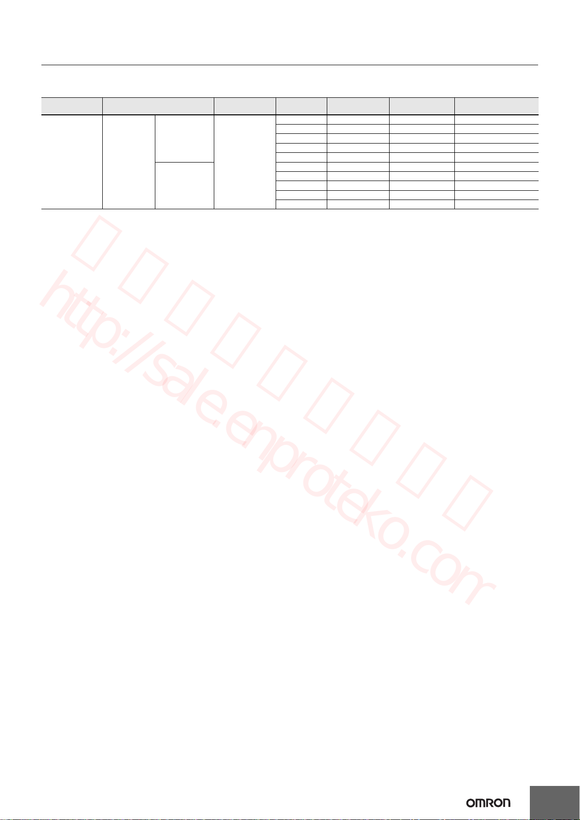
MTBF 135,000 hrs 135,000 hrs
Warranty 1 year 2 years 1 year 2 years
Output indicator Yes (Color: Green) Yes (Color: Green)
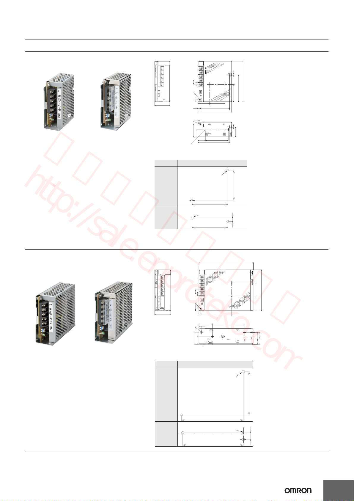
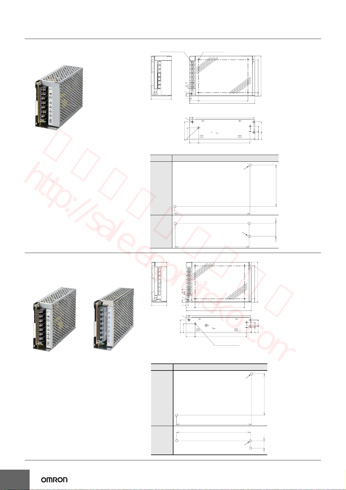
Dimensions
(W×H×D)
Bottom-mounting model 36×97×80 mm 38×98×129 mm
DIN Rail-mounting model
(See note 3.) 46×97×105 mm 46×98×154 mm
Weight (typical) Bottom-mounting model 190 g 280 g
DIN Rail-mounting model 360 g 450 g
益成自動控制材料行 http://sale.enproteko.com
益成自動控制材料行
http://sale.enproteko.com