Esquenet D2SENSE KEEPER 100 User manual

Overview
This flyer is a brief description of the major functions of the KEEPER device (please also notice the
reverse side). Please read the whole user manual before the application of the warning unit!
D2SENSE KEEPER 100
Activation and Deactivation
On/Off- push-button:The push-button has to be
pressed at least for 1 or 3 seconds respectively in order
to activate or deactivate the KEEPER. The
activation/deactivation operation is accompanied by the
segment display and a tone. The process is completed
by a high double sound and flashing Danger Zone LEDs.
If the push-button is released too early, the procedure
has to be repeated (key lock against unintended
activation and deactivation during normal operation).
Status- and Charge Level
The Status- and Charge Level-LED
indicates the status and charge level of
the KEEPER in two stages:
•Flashes green: The device is active
and the charging state is higher than
20% of the initial capacity.
•Flashes red: The battery capacity is
lower than 20%.The red LED
indication is supplemented by a
periodic warning tone.
LEDs Danger Zone 1 LEDs Danger Zone 2
Number of
persons in
warning zone
Status- and
Charge Level-LED Coupling push-
button
On/Off- push-
button
Device Coupling-
Status LED
Antenna
Connectors
Coupling BEEPER and KEEPER
See BEEPER brief instruction!
Stand 01/2014
See over
USB Connection
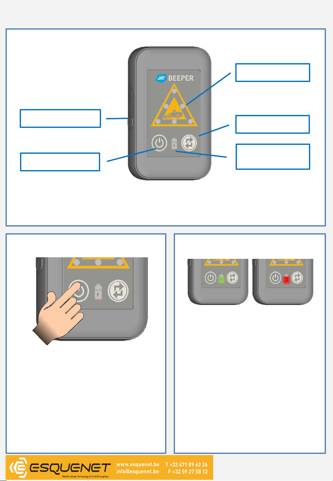
D2SENSE BEEPER 100
Overview
This flyer is a brief description of the major functions of the BEEPER device (please also notice the
reverse side). Please read the whole user manual before the application of the warning unit!
Activation and Deactivation
On/Off- push-button: The push-button has to be
pressed at least for 1or 3 seconds respectively in
order to activate or deactivate the BEEPER. The
activation/deactivation operation is accompanied
by the segment display and a tone. The process is
completed by a short vibration, a high double
sound and a flashing Danger Zone LEDs. If the
push-button is released too early, the procedure
has to be repeated (key lock against unintended
activation or deactivation during normal
operation).
Status- and Charge Level
The Status- and Charge Level-LED
Indicates the operation and charge level of the
BEEPER in two stages
•green: The device is active and the charge
level is higher than 20%of the initial
capacity.
•red: The battery capacity is lower than 20%.
The red LED indication is supplemented by
a periodic warning tone and vibration.
Operating status:
•LED off: BEEPER is deactivated.
•Red LED is illuminated continuously:
BEEPER is deactivated and is charged.
•Green LED is illuminated continuously :
BEEPER is deactivated and fully charged.
•LED flashes: BEEPER is activated.
Stand 01/2014
See over
USB Connection
LEDs Danger Zones
On/Off- push-button
Status- and Charge
Level-LED
Coupling push-
button

D2SENSE BEEPER 100
Alarming Function
The alarming is permanent if the BEEPER has been recognized
within the direct surrounding of a KEEPER. (Danger Zone 1).
The Danger Zone LEDs, the vibration alarm and the warning
sound inform the user that the current BEEPER device has been
recognized within the danger zone of a KEEPER unit Get into
visual contact with the machine driver immediately!
Wearing the BEEPERs
The BEEPER may be worn at
the front pocket, the belt or the
helmet:
Die Verbindung kann nur durch einen Neustart des KEEPERs
aufgehoben werden
Coupling of BEEPER and KEEPER
The coupling push-button
of the KEEPER is pressed
for 3 seconds.
The coupling LED
flashes and the BEEPER
may be connected.
Press the coupling push-
button for 3 seconds, until the
Operation- and Charge Level
LED flashes.
After a successful coupling the
BEEPER does not react on the
KEEPER anymore and the
coupling LED of the KEEPER is
illuminated green.
Battery Charging
The coupling connection can only be canceled by a restart of
the KEEPER (complete activation/deactivation) !
Step 1: Lift the protection cap
and move it to the left or to
the bottom.
Top Site
Step 2: Connect the micro
USB charging cable to the
BEEPER receptacle.
During charging the Charge
Level LED is continuously
red. If the LED is continuously
green, the charging
procedure is completed.
3
Attention:
The movement paths must be
checked at all times
independent of the alarming
function!
Stand 01/2014
See over
12
4

D2SENSE KEEPER 100
Alarming Function
The warning LEDs indicate that pedestrian(s) have been
recognized within the danger zone Get into visual contact
immediately!
The Danger Zone 2
LEDs flash yellow if
pedestrians equipped
with BEEPER are
recognized within
medium range to the
KEEPER device.
The Danger Zone 1
LEDs flash red if
pedestrians equipped
with BEEPER are
recognized within short
range to the KEEPER. An
additional warning
sound occurs.
Battery Charging
Step 1: Lift the protection cap
and move it to the left or to
the bottom.
Top Site
Step 2: Connect the micro
USB charging cable to the
BEEPER receptacle.
During charging the Charge
Level LED flashes red/green if
the KEEPER is active or
continuously red if the
KEEPER is off. The LED
flashes continuously green
when the charging procedure
is completed.
Installation of the KEEPER
The KEEPER should be installed as high as possible within the
driver‘s cabin to achieve a good radio coverage. One or two
external antennas might be also required at the outside of the
machine. The visual field of the driver must not be impaired!
The KEEPER may be installed by using the included holder.
Please notice the safety instructions and the system verification
procedure as published in the user manual.
Stand 01/2014
Segment Display
Attention:
The driving paths must be
checked at all times
independent of the alarming
function!
The segment display indicates
how many people equipped
with BEEPER have been
recognized within the red
Danger Zone 1.
Persons within the yellow
Danger Zone 2 are not
considered.
See over
Popular Industrial Electrical manuals by other brands


Eaton
Eaton CI-K2 Series Instruction leaflet

Addi-Data
Addi-Data MSX-Box-500 Technical description

Murata
Murata GQM22M5C2H560GB01 Series Reference sheet

Murata
Murata GCM21BC71E475KE36 Series Reference sheet

Murata
Murata GRM1885C1H271JA01 Series Reference sheet

Murata
Murata GRM0225C1E8R0CA03 Series Reference sheet


