© 2019 Leviton Mfg. Co., Inc.
For Technical Assistance Call: 1-800-824-3005 (USA Only) or 1-800-405-5320 (Canada Only) www.leviton.com
LIMITED 5 YEAR WARRANTY AND EXCLUSIONS
LevitonwarrantstotheoriginalconsumerpurchaserandnotforthebenefitofanyoneelsethatthisproductatthetimeofitssalebyLevitonisfreeofdefectsinmaterialsandworkmanship
under normal and proper use for three years from the purchase date. Leviton’s only obligation is to correct such defects by repair or replacement, at its option. For details visit www.
leviton.com or call 1-800-824-3005. This warranty excludes and there is disclaimed liability for labor for removal of this product or reinstallation. This warranty is void if this product
is installed impro perly or in an improper environment, overloaded, misused, opened, abused, or altered in any manner, or is not used under normal operating conditions or not in
accordance with any labels or instructions. There are no other or implied warranties of any kind, including merchantability and fitness for a particular purpose, but if any implied
warranty is required by theapplicablejurisdiction, the duration of anysuch implied warranty, including merchantability and fitness fora particular purpose, is limitedto five years. Leviton
is not liable for incidental, indirect, special, or consequential damages, including without limitation, damage to, or loss of use of, any equipment, lost sales or profits or
delay or failure to perform this warranty obligation. The remedies provided herein are the exclusive remedies under this warranty, whether based on contract, tort or otherwise.
FOR CANADA ONLY
For warranty information and/or product returns, residents of Canada should contact Leviton in writing at Leviton Manufacturing of Canada ULC to the attention of the
Quality Assurance Department, 165 Hymus Blvd, Pointe-Claire (Quebec), Canada H9R 1E9 or by telephone at 1 800 405-5320.
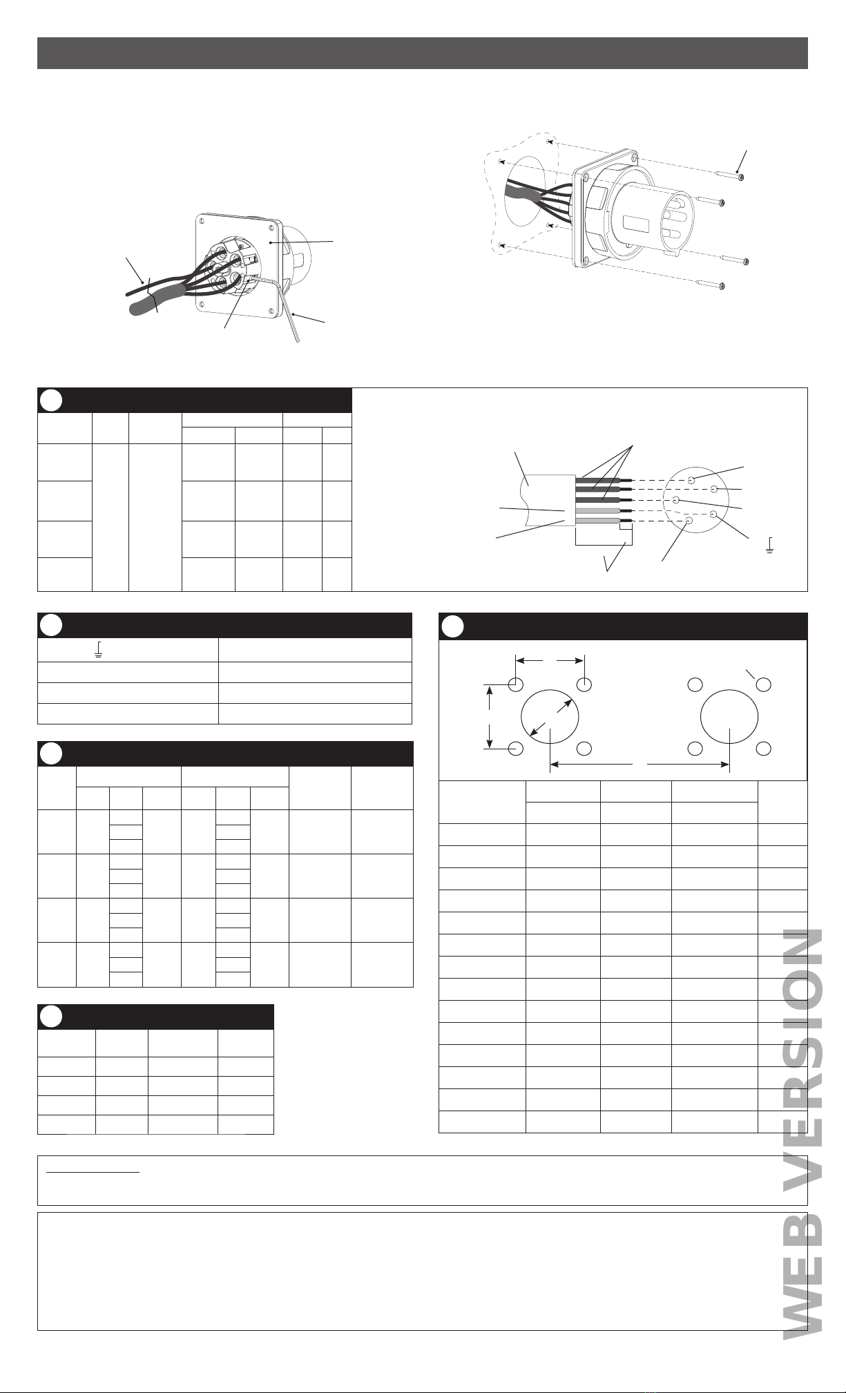
Cable Stripping Guide
Device No.
Wires
No.
Conductors
Cable Jacket (A) Conductor (B)
Inches mm Inches mm
20A
All All
1.375 35 0.375 10
30A 1.625 41 0.625 16
60A 3 76 1 25
100A 3.5 89 1 25
1
Cable Jacket Hot conductors (no specific color identification)
Green equipment grounding
conductor only (or green with
yellow stripes).
White or gray,
system ground or
neutral conductor only.
L2
L1
White dot and N
L3
Green dot and
A
B
(SeeTable 1)
Stripping and Wiring Diagram
Terminal Identification Chart
and green color Equipment ground conductor
N and white color Grounded circuit conductors (neutral)
L1, L2, L3 Ungrounded circuit conductors (line, hot)
Pilot Control circuit conductor.
2
Wire Sizes
Device
From To Grip Range
Min./Max.
Wire Diam.
(in)
Grip Range
Min./Max.
Wire Diam.
(mm)
AWG COND TYPE AWG COND TYPE
20A #14
3
S #10
3
S0.330/0.830 8/2144
55
30A #12
3
S#8
3
S or W 0.580/1.125 15/2944
55
60A #8
3
S or W #2
3
W 0.875/1.450 22/3744
55
100A #6
3
W#0
3
W 0.725/1.600 18/4144
55
3
Screw Tightening Guide in-lbs (N-m)
Device Terminal
Screws
Pilot Terminal
Screws
Assembly
Screws
20A 20 (2.26) N/A 8 (0.9)
30A 20 (2.26) N/A 8 (0.9)
60A 50 (5.65) 20 (2.26) N/A
100A 50 (5.65) 20 (2.26) N/A
4
Drilling Plan
Receptacles & Inlets
No. Wires; Device
A B C (min) D
Inches mm Inches
mm Inches mm
20A;3 Receptacle 3.26 83 3.12 79.5 3.94 100 #10
20A;3 Inlet 3.26 83 3.12 79.5 3.94 100 #10
20A;4 Receptacle 3.26 83 3.12 79.5 4.33 110 #10
20A;4 Inlet 3.26 83 3.12 79.5 4.33 110 #10
20A;5 Receptacle 3.26 83 3.12 79.5 4.92 125 #10
20A;5 Inlet 3.26 83 3.12 79.5 4.92 125 #10
30A;3 Receptacle 3.26 83 3.12 79.5 5.12 130 #10
30A;3 Inlet 3.26 83 3.12 79.5 5.12 130 #10
30A;4 Receptacle 3.26 83 3.12 79.5 5.12 130 #10
30A;4 Inlet 3.26 83 3.12 79.5 5.12 130 #10
30A;5 Receptacle 3.26 83 3.12 79.5 5.71 145 #10
30A;5 Inlet 3.26 83 3.12 79.5 5.71 145 #10
60A; All 2.76 70 3.86 98 6.69 170 #10
100A; All 3.47 88 4.88 124 7.87 200 #10
B
C
A
B
5
1. Wire.
Cut and strip cable jacket and conductors (See Table 1 and Stripping and Wiring
Diagram).
WARNING: TO AVOID FIRE, SHOCK OR DEATH, connections must be made in
the same sequence as existing device connections.
Connect wires. (See Table 2 and Stripping and Wiring Diagram). Tighten terminal
screws (Table 4).
NOTE: Separate grounding wire has been pre-installed. Connect ground wire first.
terminal screws
grounding wire
(pre-attached)
Allen key
(included)
2. Mount.
Mount (Table 5) and tighten mounting screws.
mounting screws
(not included)
gasket
(pre-attached)
60A and 100A Inlet Installation
If mounting to a backbox, use Leviton:
BX60LEV (60A), BX100LEV (100A) - non-metallic
BX60LEVM (60A), BX100LEVM (100A) - metallic
clearance hole for
“D” size screw


