ESS SFoam User manual

ESS Sfoam Dust Suppression 1 14/06/2021
ESS SFoam
Dust Suppression Foam Generation Units
Installation/ Operations Manual

ESS Sfoam Dust Suppression 2 14/06/2021
National OfficeDetails
Location
Address
Phone & Email
CURRUMBIN
11 –13 Traders Way
PO Box 121
Currumbin QLD 4223
(07) 5589 2000
esscur@esseng.com.au
GLADSTONE
Unit 2/34 Chapple Street
PO Box 1475
Gladstone QLD 4680
(07) 4972 3759
essgla@esseng.com.au
KALGOORLIE
Unit 1/ 182 Boulder Rd
Kalgoorlie WA 6430
PO Box 10471
Kalgoorlie WA 6433
(08) 9021 7991
esskal@esseng.com.au
KARRATHA
26 Midas Road
Malaga WA 6090
(08) 9248 4111
esskar@esseng.com.au
MACKAY
1 Progress Street
Paget, QLD 4740
PO Box 5755
Mackay Mail Centre QLD
4741
(07) 4952 4600
essmac@esseng.com.au
MAITLAND
Unit 2 Barton Court 6
Johnson Street
Maitland NSW 2320
(02) 4932 3544
essmai@esseng.com.au
PERTH
26 Midas Road
Malaga WA 6090
(08) 9248 4111
essper@esseng.com.au
TOWNSVILLE
Unit 4/ 585 Ingham Rd
Mt St John
Townsville QLD 4818
(07) 4952 4600
esstow@esseng.com.au
SOUTH AUSTRALIA
38 Montpelier Terrace Port Elliot
SA 5212
0408 948 175
esssa@esseng.com.au
VICTORIA
Unit 4 / 238 Governor Road
Braeside VIC 3195
(03) 9587 3979
essvic@esseng.com.au
WOLLONGONG
Unit 1 / 20 Doyle Avenue
PO Box 343
Unanderra NSW 2526
(02) 4272 4422
esswol@esseng.com.au
TOLL FREE 1800 074 446 FROM ANYWHERE IN AUSTRALIA
VSS TOLL FREE 1800 300 877

ESS Sfoam Dust Suppression 3 20/05/2020
WARRANTY NOTE
ESS WARRANTS the ESS SFoam to be free of defects both in materials and workmanship
for a period of 12 months from the date of despatch of the product from the ESS factory.
The warranty given by ESS in this regard will extend only to replacing or repairing product
shown to be defective.
The warranty also is subject to the following restrictions:
(a) Installation of the product contrary to the instructions contained in the supplied manual
will void such warranty absolutely;
(b) The warranty will not extend to any liability for injuries incurred and which result from
the use of the product contrary to the instructions in the manual;
(c) Save as prescribed by law, ESS will not be liable for any damage sustained by a
purchaser or a third party by way of consequential loss arising out of defects in the
product.
You are asked to note that ESS offers purchasers a service whereby either:
(a) It will install the product and certify the correctness of such installation, or
(b) Certify the correctness or otherwise of the installation of the product by third parties.
This certification service is designed to ensure that you obtain the full benefit of the ESS
warranty hereby provided. If you would like to take advantage of the installation certification
service provided, please contact ESS regarding the service.
Refer to the Final Checklist at the back of this manual.
Visit the ESS website www.esseng.com.au to register your product warranty.
THE CONTENTS OF THIS MANUAL ARE COPYRIGHT TO:
ESS ENGINEERING SERVICES AND SUPPLIES PTY LTD
ALL RIGHTS RESERVED
Information contained herein is for use in the operation of the ESS SFoam, purchased from
ESS and cannot be passed on to any other party without express permission, in writing, from
ESS.

ESS Sfoam Dust Suppression 4 20/05/2020
INDEX
SECTION 1
SCOPE
SECTION 2
INSTALLATION
SECTION 3
START UP & COMMISSIONING
SECTION 4
SHUT DOWN
SECTION 5
TROUBLE SHOOTING
SECTION 6
MAINTENANCE
SECTION 7
APPENDIXES
SECTION 8
FINAL CHECKLIST

ESS Sfoam Dust Suppression 5 20/05/2020
SECTION 1 –SCOPE
This manual details the installation, operation and maintenance requirements for the ESS SFoam
Senior and SFoam Junior standard units as well as associated hardware such as expansion pots
and spray nozzles. This equipment is designed to produce foam of consistent properties which can
be used as a dust suppressant.
PRINCIPLE OF OPERATION
The SFoam dosing process is activated by the energizing of two solenoid valves which control the
flow of compressed air and water. The solenoids can be controlled by manual switching or in
automatic mode via a remote signal.
The flow of water initiates the operation of the dosing feeder which then injects the SFoam dust
suppression chemical in to the water line. The solution concentration can be manually adjusted at
the dosing feeder head between 0.2% and 1.6% concentration. As the dosing feeder is of the
proportioning type, the solution concentration will remain constant even if the water flow rate
fluctuates.
Pressure regulators are installed on both the air line and the solution line.
The foam is activated in an expansion chamber which is capable of supplying foam to up to six
dosing points. The SFoam Junior is capable of supplying on to two chambers whilst the SFoam
Senior is capable of supplying two to three chambers (depending on line distance and pressure
constraints).
Refer to Fig. 1 for a schematic of a typical system.
Fig. 1 Schematic of a typical SFoam Application

ESS Sfoam Dust Suppression 6 20/05/2020
Fig 2 SFoam Senior Unit
Fig SFoam Junior Unit

ESS Sfoam Dust Suppression 7 20/05/2020
Supply Ports to
Dosing Points
Expansion Chamber
Air and Solution
Rotameters (FlowMeters)
Air and Solution
Flow Control
Valves
Fig 4 SFoam Expansion Chamber
Fig 5 Type A Nozzle Mounting Bracket Fig 6 Type b Nozzle Mounting Bracket

ESS Sfoam Dust Suppression 8 20/05/2020

ESS Sfoam Dust Suppression 9 20/05/202
SECTION 2 –INSTALLATION
Services Required
Electrical: 90 to 260Vac, 50/60 Hz, single phase.
Water: SFoam Junior. 10 –40 litres/min @ 410 kPa Min.
SFoam Senior. 10 –75 litres/min @ 410 kPa Min.
Compressed Air: SFoam Junior. 25 - 75 cfm @ 75 psi Min.
(12 to 35 l/sec @ 520 kPa Min).
SFoam Senior. 25 - 150 cfm @ 75 psi Min.
(12 to 70 l/sec @ 520 kPa Min).
WARNING: The recommended minimum water and air pressures are extremely important. If a
minimum of 410 kPa water pressure and 75 psi air pressure cannot be achieved then foam
distribution and quality will be severely affected. However, if the expansion chambers are
installed 5 metres or more above the SFoam unit then higher supply pressures will be
required. As a “rule of thumb”, water pressure should be increased 50 kPa for every 5 metres
of elevation.
Expansion Chambers
SFoam Junior: Depending on line distances and pressure constraints, the
SFoam Junior is capable of supplying one or two chambers
SFoam Senior: Depending on line distances and pressure constraints, the
SFoam Senior is capable of supplying two to three chambers.
Pre-Installation Check List
Ensure that the water supply is reliable adequate and of the correct quality. A
booster pump may be required. Note: A minimum water pressure of 410
kPa is required.
Ensure that the compressed air supply is reliable, adequate and of the
correct quality. Note: A minimum pressure of 75 psi is required.
Ensure that either a 90 to 260Vac, 50/60 Hz, single phase supply is
available.
Ensure that the electrical protection is adequate. Other protection classes
are available upon request. Are there any other site specific electrical
requirements?
Ensure that the proposed site for the SFoam Junior/Senior has good access
for the installation/removal of chemical drums or totes of SFoam and is
(preferably) centrally located between the foam application points.
Expansion chambers must be installed in such a location that each dose
point is a equal distance from the supplying chamber or each supply hose is
of equal length (to prevent preferential dosing).

ESS Sfoam Dust Suppression 10 20/05/2020
Mechanical Installation
Install the SFoam Junior/Senior at ground level on a level site with good access to
the required services.
The SFoam Junior/Senior unit comes complete with Ø25 mm male screwed BSP
connections for the water and air lines and a Ø12 mm N.B. tube connection for the
chemical line.
It is recommended that the unit be situated as close as practicable to the chemical
storage tank, tote or drum. A flooded suction condition is preferred.
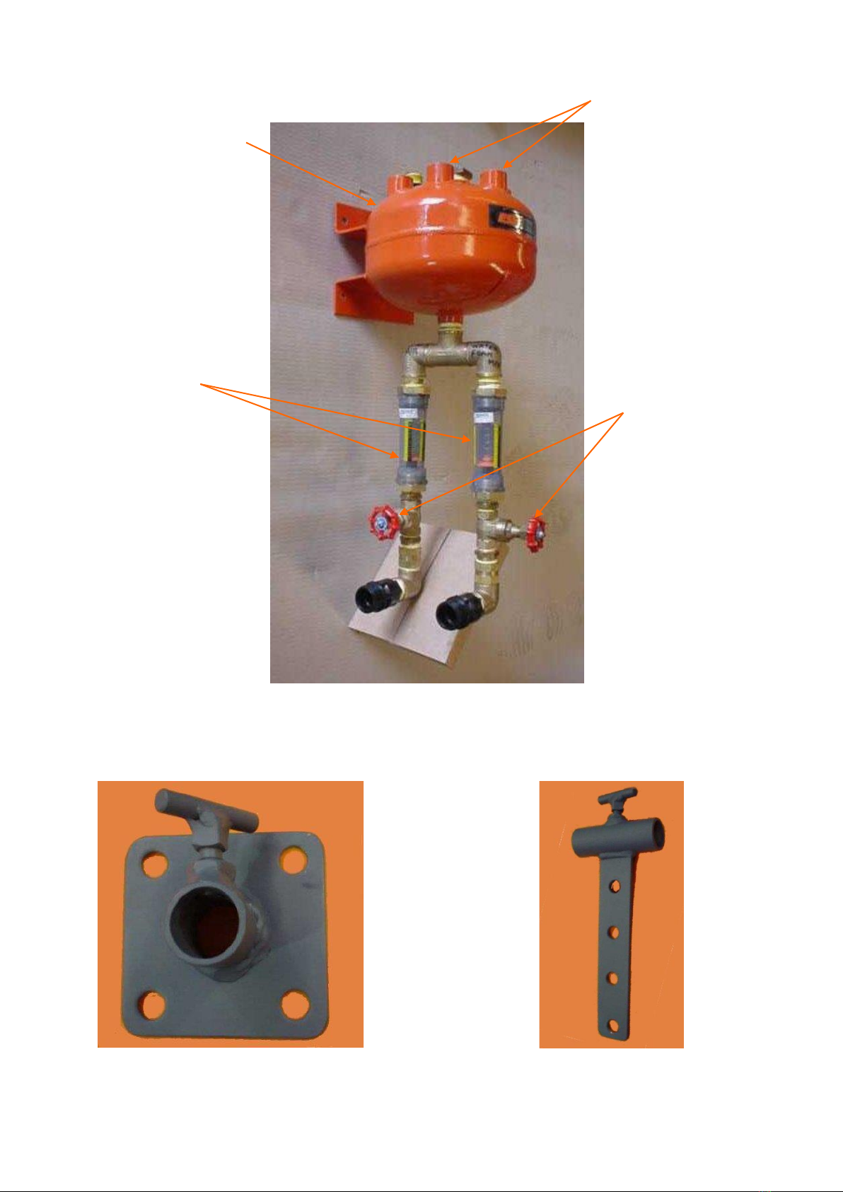
Each expansion chamber should be installed such that the foam delivery lines are
located at the top of the chamber and the solution and air inlets are located at the
bottom of the chamber. The expansion chambers should be located as close as
possible to the dose points.
Install a non-return valve to the air line on the inlet side of the expansion chamber.
When connecting the solution and air supply line to the expansion chambers, ensure
that the air line is connected to the Omega 510 flow meter and the solution line is
connected to the omega 505 flow meter. Note: It is recommended that each inlet
or delivery hose/pipe be a minimum of Ø20mm inside diameter with individual
foam delivery lines to be of lengths less that 15 meters.
Ensure that all pipe/hose lines are secured safely and tidily using weld-on double
pipe clamps or similar.
Connect the SFoam suction tube to the dosing feeder by unscrewing the securing
ferrule. For drums, fit the foot-valve to the end of the tube and place inside the drum.
For Bulki-Bins, a Camlock adapter must be attached to the container outlet and the
suction tube fits over the tail of the adaptor. For suction tube lengths greater than 2
metres, pre-fill the line with chemical to reduce delay at start-up. Note: The
maximum recommended suction tube length is 4 metres.
Select the desired solution concentration by turning the adjusting screw on the
dosing feeder and read the graduated scale. Note: DO NOT ADJUST SOLUTION
CONCENTRATION WHILE THE DOSING FEEDER IS OPERATING, THIS WILL
DAMAGE THE DOSING FEEDER.
Refer to appendix A for details regarding the typical setup of dose points utilising the
various brackets and nozzle types available.
Electrical installation
Note: All electrical installation work should be undertaken by an electrician or
other suitable qualified electrical person.
The SFoam unit will accept 90 to 260Vac single phase power. Refer to the electrical
schematic in Appendix E for further details.
A 24Vdc field switch such as a proximity probe, ultrasonic detector or photoelectric
cell can also be used to automatically start/stop the SFoam unit. Such a device
should be connected across terminals 2 and 6. A volt free N.O. contact may also be
used. Refer to Appendix E for further details.

ESS Sfoam Dust Suppression 11 20/05/2020
SECTION 3 –START UP AND COMMISSIONING
First Time Startup (Commissioning)
Ensure that SFoam chemical, air and water are available to the unit. That is, all
valves in the delivery lines are in the OPEN position.
Ensure that the red “POWER” on lamp is illuminated.
Ensure that the “AUTO/OFF/MANUAL” selector switch is in the “OFF” position.
Select the desired solution concentration by turning the adjusting screw on the
dosing feeder and read the graduated scale. During first time startup, use a
concentration of 0.8%. Note: DO NOT ADJUST SOLUTION CONCENTRATION
WHILE THE DOSING FEEDER IS OPERATING AS THIS WILL DAMAGE THE
DOSING FEEDER.
Momentarily open the ball-valve at the discharge of the T-strainer to bleed
entrapped air from the water line.
Observe the water pressure on the gauges before (SFoam Senior only) and after
the pressure regulator. The water supply pressure should be a minimum of 410 kPa.
Water Pressures less than this may affect foam quality. If necessary, adjust the
regulating valve to change the set pressure. Note: DO NOT EXCEED 600 kPa
REGULATED PRESSURE AS THIS WILL CAUSE DAMAGE TO THE DOSING
FEEDER.
Observe the air pressure on the gauges before (SFoam Senior only) and after the
pressure regulator. The air supply pressure should be a minimum of 75 psi (520
kPa). Adjust the regulator if necessary to achieve the required pressure.
Turn the knob on the top of the dosing feeder to the “ON” position.
Turn the “AUTO/OFF/MANUAL” selector switch to “MANUAL”. The air and water
solenoids will now open and the green “RUN” lamp will be illuminated. Observe the
air and water regulated pressure and ensure that it does not drop substantially from
set pressure. Any substantial drop in pressure may indicate that there is insufficient
supply volume. For compressed air, this may entail the installation of a compressor
with larger capacity. For water, the installation of a break-water tank and booster
pump may be required.
Ensure that the SFoam chemical is feeding through the suction tube.
At the first expansion chamber, set the solution supply at approximately 8 to 10
litres/minute by adjusting the gate valve. When flow is confirmed, open the gate
valve on the air supply line until the desired foam consistency is achieved. Note:
Ideal foam consistency can be described as a thick, dense, self-supporting
foam similar to that of shaving cream.
Repeat the previous step for any other expansion chambers.
If the unit is to be automatically run off an external control signal, turn the
“AUTO/OFF/MANUAL” selector switch to “AUTO”. Ensure that the unit starts
automatically when called for by the external signal. Note: Two timers are utilized
in AUTO mode –a Start timer (which energises the solenoids after a pre-set
time) and a Stop timer (which de-energises the solenoids after a pre-set time).
These timers should be adjusted by an electrician or other suitably qualified
electrical person.

ESS Sfoam Dust Suppression 12 20/05/2020
SECTION 4 –SHUT DOWN
Temporary Shut-Down
Turn the “AUTO/OFF/MANUAL” selector switch to the “OFF” position.
Close the water, solution and air supply valves to the unit.
Short Term Shut-Down (Two Months or Less)
Turn the “AUTO/OFF/MANUAL” selector switch to the “OFF” position.
Close the air supply valve at the inlet to the SFoam unit.
Remove the SFoam chemical suction tube from the supply container and instead,
place the end in a container of water (a 10 litre bucket will be sufficient).
Adjust the concentration at the dosing feeder so that the maximum concentration is
obtained.
Turn the “AUTO/OFF/MANUAL” selector switch to the “MANUAL” position.
Run the SFoam unit for a few minutes or until it is apparent that all lines have been
flushed clean.
Turn the “AUTO/OFF/MANUAL” selector switch to the “OFF” position.
Close all valves in the air and water lines to and from the SFoam unit including all
gate valves at the expansion chambers.
Remove mains power from the unit.
Long Term Shut-Down (Over Two Months or For Transportation)
Complete the short term procedure as detailed above.
Bleed all pressurised lines.
Disconnect all lines and ensure that they are free of fluid for transportation.

ESS Sfoam Dust Suppression 13 20/05/2020
SECTION 5 –TROUBLE SHOOTING
When troubleshooting a typical SFoam installation, it is strongly recommended that a portable
pressure gauge be carried so water and air pressures can be checked at various points in the
system.
PROBLEM DESCRIPTION
ACTION
Poor foam quality –runny, wet foam
Insufficient air supply.
Check compressed air supply flow and pressure.
Poor foam quality –dry foam
Insufficient water supply.
Check water supply flow and pressure.
Poor quality foam –other
Insufficient SFoam in solution.
Check dosing feeder solution concentration.
Check supply valve and suction tube.
No foam
Unit off.
Check POWER lamp.
Check solenoids are open when RUN lamp is lit.
Check external control signal if in AUTO mode.
Check valves in delivery lines.
Check water and air availability.
Check SFoam availability in storage container.
Insufficient water flow
Check pressure and flow.
Remove Y-strainer element and re-check pressure and flow.
Clean if necessary.
Check correct valve positions in delivery lines.
Check booster pump output (if installed).
Insufficient air flow
Check pressure and flow.
Check correct valve positions in delivery lines.
Poor foam distribution
Check and clean nozzles or spray bar outlets.
Check water and air pressure.
Preferential foam distribution
Check delivery line lengths to ensure they are all the same
length.
Check valve positions on delivery lines.

ESS Sfoam Dust Suppression 14 20/05/2020
SECTION 6 - MAINTENANCE
Typically, the SFoam unit should require minimal maintenance, however, regular inspection to
confirm correct operation is recommended.
All maintenance procedures should be performed with the unit shut-down. Refer to the temporary
shut-down procedure.
Cleaning and Preventative Maintenance Intervals
DESCRIPTION
MONTHLY
HALF
YEARLY
YEARLY
Inspect and record water meter totaliser
Inspect and clean water y-strainer
Inspect and clean check valves
Inspect and clean solenoid valves
Inspect system for leaks and damage
Inspect and record hours run meter
Inspect and record SFoam stock levels
Inspect and clean pressure relief valve
Inspect and record air and water pressures
Refer to Appendix B for a typical Site Service Log Sheet as used by ESS Engineering Pty Ltd when
servicing SFoam units.

ESS Sfoam Dust Suppression 15 20/05/2020
SECTION 7 - APPENDIXES
Appendix A Typical Setup Information
Appendix B ESS Engineering Pty Ltd –Site Service Log Sheet
Appendix C SFoam Senior General Arrangement Drawing
Appendix D SFoam Junior General Arrangement Drawing
Appendix E SFoam Power/Control Schematic Diagram

ESS Sfoam Dust Suppression 16 20/05/2020
Each site installation is unique and needs to be designed on a case-by-case basis.
However, there are some general guidelines that can be followed to ensure that
optimum performance is achieved.
Minimum Air and Water Requirements
The most common problem encountered with SFoam installations is that the minimum
air and water requirements are not met by the customer. Whilst the minimum
requirements given in this manual are rules of thumb only, it is better to have too much
than too little.
Minimum pressures should be 410 kPa for water and 520 kPa for air for a typical system
comprising no more than two expansion chambers which are installed no more than 5
metres above the SFoam Junior/Senior unit.
The customer should also be able to guarantee the supply of a minimum of 40 l/min of
water for a SFoam Junior and 75 l/min of water for a SFoam Senior. In practice, the
SFoam unit may use less than this but if these quantities are not guaranteed prior to
installation then problems may be encountered requiring the installation of a booster
pump.
Similarly with compressed air, 75 cfm and 150 cfm is the minimum recommended
requirement for the SFoam Junior and SFoam Senior respectively.
Be aware that the higher and further an expansion chamber is from the SFoam unit, the
greater the water and air supply pressure that is required. A useful rule of thumb is that
the water supply pressure should be increased 50 kPa for every 5 metres of head. Do
not exceed 600 kPa regulated water supply pressure or the dosing feeder may be
damaged.
Booster Pump Installation
Should a water booster pump be required, it should be installed in the water line prior to
the SFoam unit. A break-water tank of 1000 litres nominal capacity complete with a
ball-float-valve is also recommended should a booster pump be necessary.
ESS prefers Grundfos pumps for these purposes. The recommended Grundfos pump
is:
Grundfos CR4-80, 1.5kW, 4.5m³/hr @ 60 m
Foam Quality
The best foam is a thick, dense, self-supporting foam. A good test is one where you
have some foam in your hand and you draw a line in it with your finger forming a void. If
the void stays there for a while, it is self-supporting and a good foam. The foam should
be dry, not wet and “globby”.
Experience has shown that solution concentrations between 0.4 and 0.9% give the best
quality foam.
APPENDIX A Typical Setup Information

ESS Sfoam Dust Suppression 17 20/05/2020
Typical Dosing Points
The best points for the application of SFoam are at the feed point of crushers, inside
conveyor transfer chutes and similar points where the action of the material will tend to
mix and thoroughly coat the material with foam before the dust has been created. It is
too late to try and treat the material after the dust has been generated.
Crushers
It is best to apply the foam on to the material before it gets crushed and as a result it is
best to come in from above or into the cascading material. Open ended pipes can be
used as a first choice but it must be ensured that good foam distribution is achieved.
As an alternative, pigs-tail nozzles can be used (ref Fig. 8). These nozzles can be used
in conjunction with the Type C nozzle mounting brackets (ref Fig. 7) if they are in danger
of being hit by falling material.
Typically, one expansion chamber is used to supply foam to a crusher (say 600 tph
capacity) with three dose points in to the cascading material and three in to the crusher.
Transfer Points
It is best to direct the foam in to the transfer chute towards the falling material. Once
again, open pipes or pigs-tail nozzles can be used in conjunction with the Type A nozzle
mounting brackets (ref Fig. 5) or Type B nozzle mounting brackets (ref Fig. 7).
Typically, three or four nozzles are directed in to the falling material whilst one or two
others are directed in to the chute exit, or alternatively with a spray bar running at an
angle of forty-five degrees to the direction of exit conveyor travel.
Conveyors
Spray bars are most successfully utilized when applying foam to conveyors. Typically, a
Ø25mm diameter spray bar (with a tee in the middle for foam inlet) is fabricated from
polyethylene or PVC pipe with eight to ten holes of between Ø6mm to Ø10mm diameter
to apply the foam spray. The holes at the end of the bar should be of the larges
diameter to prevent preferential spraying at the centre of the bar.
The spray bar is best setup at an angle of forty-five degrees to the direction of conveyor
travel.
Where spray bars are not practical, multiple pigs-tail nozzles or as a last resort, open
pipes can be utilized. Typically, four dose points are needed in these instances to
achieve the required coverage. That is, two dose points each side of the belt to apply
foam across the full width of the belt. The open pipes and pigs-tail nozzles can be easily
secured to the conveyor support structure using Type B nozzle mounting brackets (ref
Fig.5).
Large, Open Areas
Should foam need to be applied to large open areas, pigs-tail nozzles should be utilized.
Duck-Bill spray nozzles (Fig. 9) can be used as an alternative but these are only suitable
when the solution flow is greater than 30 litres per minute to the point of application.
The Ducks-Bill nozzle may need to be squeezed in a vice to achieve the most
adequate orifice size.

ESS Sfoam Dust Suppression 18 20/05/2020
SFoam Site Service Sheet
ACTIVITY
RESULT
ACTION TAKEN
Leaks Inspection
Water filter –inspection and service
Proportional Pump - Inspection
Regulators and Solenoids - Inspection
Operating Hours –record reading
Water Meter –record reading
SFoam Stock Level –record reading
Auto mode –check operation
SFoam MSDS –check availability
Inlet Water Pressure –check and record
Regulated Water pressure –check and record
Inlet Air Pressure –check and record
Regulated Air Pressure –check and record
Check Flow - Record Flow Meter Readings
EXPANSION CHAMBER
WATER FLOW
AIR FLOW
1
2
3
4
Comments:
Client Signature: Date:
Note: SFoam unit must be inspected whilst
operating. If unit is not operating, obtain
site managers approval to operate in
“Manual” mode for inspection and testing.
APPENDIX B ESS Engineering Services and Supplies Pty Ltd –Site Service Log Sheet
Plant:
Date:
Site Contact:
Service Technician:
SFoam Serial No.:

ESS Sfoam Dust Suppression 19 20/05/2020
APPENDIX C

ESS Sfoam Dust Suppression 20 20/05/2020
APPENDIX D
Table of contents
Popular Cleaning Equipment manuals by other brands

Hard Head
Hard Head 006259 operating instructions

Tornado
Tornado Pro Spotter Operation and maintenance manual

Truvox
Truvox Hydromist 55 Original instructions

IBS Scherer
IBS Scherer F Translation of the original instructions

Matrix Cleaning Systems
Matrix Cleaning Systems SDV8 user manual

Schiller
Schiller Little Wonder Monster Truckloader Parts and Operator's Manual