Essential Garden 640-08477458-7 User manual
USE AND CARE GUIDE
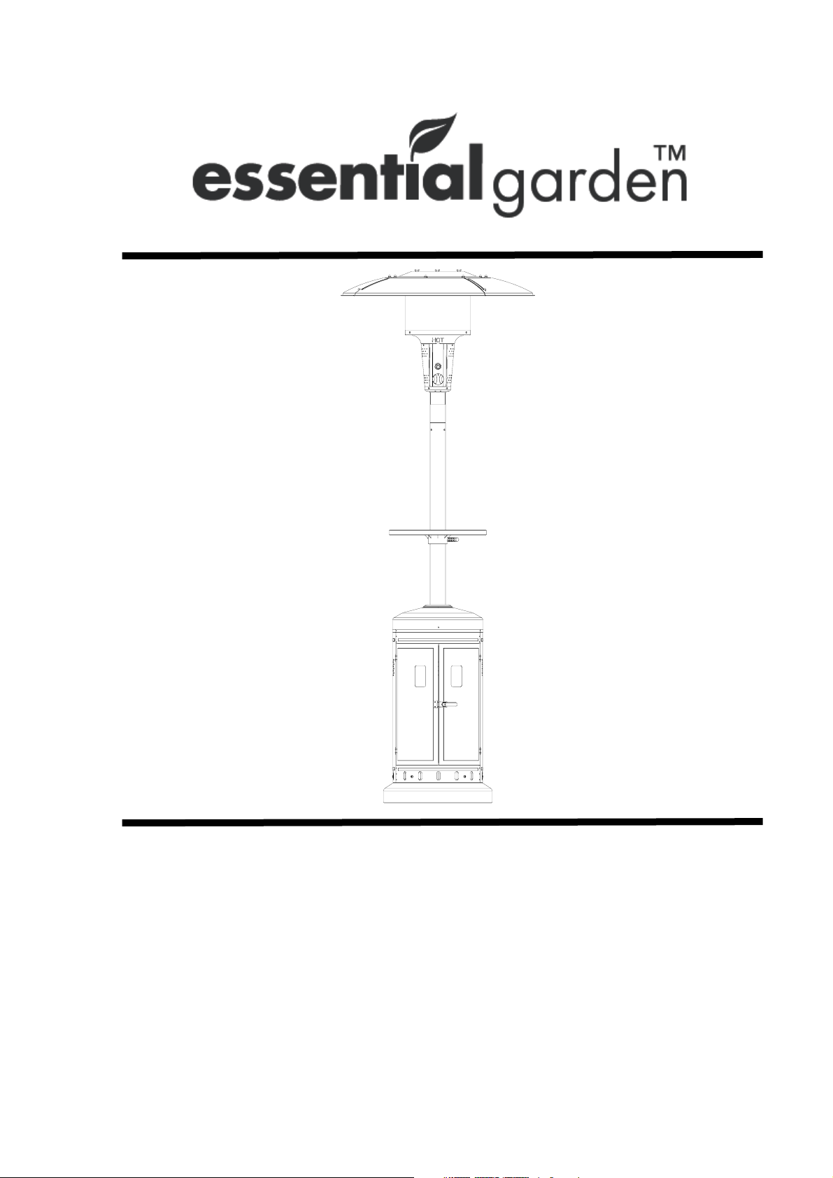
ESSENTIAL GARDEN PATIO HEATER
Product Code: 640-08477458-7
UPC Code: 6937419204603
Date of Purchase: _____/ _____/ _____

2
CARBON MONOXIDE HAZARD
zThis appliance can
produce carbon monoxide
which has no door.
zUsing it in an enclosed
space can kill you.
zNever use this appliance
in an enclosed space such
as a camper, tent, car or
home.
Save these instructions for future reference.
If you are assembling this unit for someone else,
give this manual to him or her to read and save
for future reference.
If you experience any problems with your heater, DO NOT RETRURN THE PRODUCT TO
THE STORE, please call 1-855-CHANT-US (1-855-242-6887) for
assistances. 8 am to 5 pm Eastern time, Monday to Friday.
DANGER
If you smell gas:
1. Shut off gas to appliance.
2. Extinguish any open flame.
3. If odor continues, keep away from
the appliance and immediately
call your gas supplier or fire
department.
WARNING
1. Do not store or use gasoline or
other flammable vapors and
liquids in the vicinity of this or
any other appliance.
2. An LP-cylinder not connects for
use shall not be stored in the
vicinity of this or any other
appliance.
WARNING
1. Improper installation, adjustment,
alteration, service or maintenance can
cause property damage, injury ,or death.
2. Read the installation, operation, and
maintenance instructions thoroughly before
installing or servicing this equipment.
WARNING
For outdoor use only.
DANGER

3
TABLE OF CONTENTS
.
Product Specifications………………………………………………………………..3
Safety Information……………………………………………………………….…...4
Package Contents……………………………………………………………..….…..7
Replacement parts list………………………………………………………………..8
Hardware Contents………………………………………………………….….…....9
Preparation………………………………………………………………….…..........9
Assembly Instructions…………………………………………………………….......9
Operating Instructions…………….………………………………………..…….….15
Care and Maintenance …………………………………………………..……….…16
Troubleshooting………………………………………………………..……………..18
Warranty………………………………………………………………..……….…….18
PRODUCT SPECIFICATIONS
Certification CSA
Height Overall 86.60 inches
Reflector Diameter 31.50 inches
Rated Heat Input 40,000 BTU/HR
Fuel Propane-LP
Gas Supply 20-Lb LP-Gas cylinder
Manifold Pressure 11 inches W.C
Injector Size (diameter) 1.92 mm
Safety Features Thermocouple & Tilt Switch
Gas Supply Pressure Max 150 PSI, Min 5 PSI

4
SAFETY INFORMATION
Please read and understand this entire manual before attempting to assemble, operate
or install the product. If you have any questions regarding the product, please call
customer service at: 1-855-CHANT-US (1-855-242-6887) from 8:00 am to 5:00 pm
Eastern time, Monday to Friday.
1. CALIFORNIA PROPOSITION 65 WARNING:
(a) Combustion by-products produced when using this product contain chemicals
known to State of California to cause cancer, birth defects and other
reproductive harm.
(b) Handling the brass material on this product exposes you to lead, a chemical
known to the state of California to cause cancer and birth defects or other
reproductive harm. Wash hands after handling.
2. The installation must conform with local codes or, in the absence of local codes,
with the
National Fuel Gas Code, ANSI Z223.1 /NFPA 54, Natural Gas and
Propane Installation Code, CSA B149.1, or Propane Storage and Handling
Code, B149.2.
3. Minimum clearance to the combustible materials is 44 inches.
4. Perform a leak test with a soapy solution:
(a) To check gas connections.
(b) After connecting a new cylinder.
(c) Upon re-assembly after disassembly.
Please refer to the leak test procedure indicated in this instruction manual on page
15.
Replace the hose assembly prior to the appliance being put into operation if there
is evidence of excessive abrasion or wear, or if the hose is damaged. The pressure
regulator and hose assembly supplied with the appliance must be used .The
replacement hose assembly/ regulator shall be that specified by the manufacturer.
5. If you don’t feel the heater is on a stable surface, use a ground screw to fix the base
of the heater on the surface where the heater is installed. Fix the base on an incline
no wider than 15 degrees.
6. Place the propane hose with regulator assembly out of pathways where people may
trip over it or in areas where the hose will not be subjected to accidental damage.
7. This heater is equipped with a battery-operated ignition device; please refer to the
assembly instructions on page 14.
8. Materials or items when stored under the heater will be subjected to intense heat
and could be seriously damaged.
9. Clothing or other flammable materials should not be hung on the heater, or
placed on, under or near the heater .
10. Children and adults should be alerted to the hazards of high surface temperatures
and should stay away to avoid burns or clothing ignition.
11. Young children should be carefully supervised when they are in the area of the
heater.
12. Any guard or other protective device removed for servicing the heater must be
replaced prior to operating the heater.

5
SAFETY INFORMATION
13. Installation and repair should be done by qualified service person, the heater
should be inspected before use and at least annually by a qualified service person.
14. More frequent cleaning may be required as necessary. It is imperative that the
control compartment, burners and circulating air passageways of the heater to
kept clean.
15. Keep the appliance area clear and free from combustible materials, gasoline and
other flammable vapors and liquids.
16. Do not obstruct the flow of combustion and ventilation air.
17. Keep the ventilation opening(s) of the cylinder enclosure free and clear from debris.
Use this appliance in a well-ventilated space only. Do not use it in a building,
garage, or any other enclosed area.
Use this appliance in outdoor areas described below:
(a) With walls on all sides, but at least one permanent opening at ground level and
no overhead cover.
(b) Within a partial enclosure that includes overhead cover and no more than two
walls. These walls may be parallel, or at right angles to each other.
(c) Within a partial enclosure that includes overhead cover and no more than two
walls. The following shall apply:
(i) One wall that is equivalent to at least 25% of the total wall area is
completely open.
(ii) 30% or more in total of the remaining wall area is open and unrestricted.
18. The LP-gas supply cylinder to be used must be:
(a) Constructed and marked in accordance with the Specifications for LP-gas
cylinders of the U.S. Department of Transportation of Dangerous Goods and
Commission, CAN/CSA-B339, as applicable;
(b) Provided with a listed overfilling prevention device; and
(c) Provided with a cylinder connection device compatible with the connection for
the appliance.
19. Disconnect the cylinder when the appliance is not in use.
20. Storage of an appliance indoors is permissible only if the cylinder is disconnected
and removed from the appliance.
21. Store the cylinder outdoors in a well-ventilated area (not in a building, garage, or
other enclosed area) out of the reach of children.
22. The cylinder used must include a collar to protect the cylinder valve.
23. Do not store a spare LP-gas cylinder under or near this appliance;
24. Never fill the cylinder beyond 80 percent full;

6
SAFETY INFORMATION
25. Place the dust cap tightly on the cylinder valve outlet whenever the cylinder is not in
use. Install only the type of dust cap on the cylinder valve that is provided with the
cylinder valve. Other types of caps or plugs may result in a propane leak.
26. Inspect the visible portion of the hose before each use of the appliance.
27. More frequent cleaning may be required as necessary. It is imperative that the
control compartment, burners and circulating air passageways of the heater be kept
clean.
28. Every part of the heater shall be secure against displacement and shall be
constructed to maintain a fixed relationship between essential parts under normal
and reasonable conditions of handling and usage. Parts not permanently secured
shall be designed so they cannot be incorrectly assembled and cannot be
improperly located or misaligned in removing or replacing during cleaning or other
servicing.
7
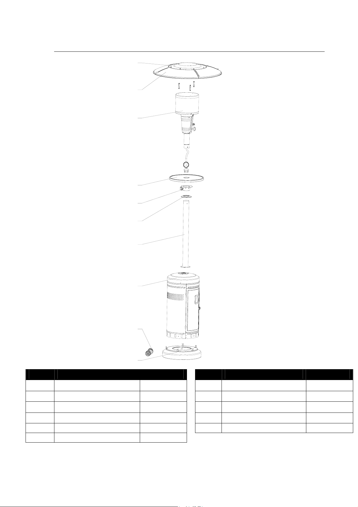
PACKAGE CONTENTS
PART DESCRIPTION QUANTITY PART DESCRIPTION QUANTITY
A Top Dome 1 G Pole Assembly 1
B KD Dome 4 H Cylinder Assembly 1
C Burner Assembly 1 I Wheel Assembly 1
D Table Assembly 1 J Base 1
E Table Support Assembly 1
F Deck Ring 1
I
J
H
G
F
E
A
B
C
D

8
REPLACEMENT PARTS LIST
PART PART NO. DESCRIPTION QTY
A CH182001 Top Dome 1
B CH182002 KD Dome 4
C CH182003 Burner Assembly 1
C1 CH182004
Burner Chamber
Assembly 1
C2 CH182005 Knob 1
C3 CH182006 Igniter 1
C4 CH182007 Thermocouple 1
C5 CH182008 Ignition Pin 1
C6 CH182009 Tilt Switch 1
D CH182010 Table Assembly 1
E CH182011
Table Support
Assembly 1
F CH182012 Deck Ring 1
G CH182013 Pole Assembly 1
H CH182014
Cylinder
Assembly 1
I CH182015 Wheel Assembly 1
J CH182016 Base 1
K CH182017 Weight Plate 1
L CH182018 Hardware Pack 1
M CH182019 Shroud Fix
Bracket 1
C6
KKM4 x8mm
Bolt(x4)
HARDWARE Model :PG182H
AAA-Battery (x 1)DD
WingNut(x 3)JJ
M8 Nut(x 2)
CCAAM 8 X15mm
Bolt(x2)
II Refl ector Spacer (x 3)
M6x 10 H exagon Head
Bolt(x 4)
EEM5x 8 P an Head Bolt (x8)
JJ
HHGGM5x 8m m Bolt (x12) 5mmWa sher (x 12)M5N ut (x1 2)
FF
C4
C5
C3 C2
C1
K
I
J
H
G
F
E
A
B
C
D
L
M
9
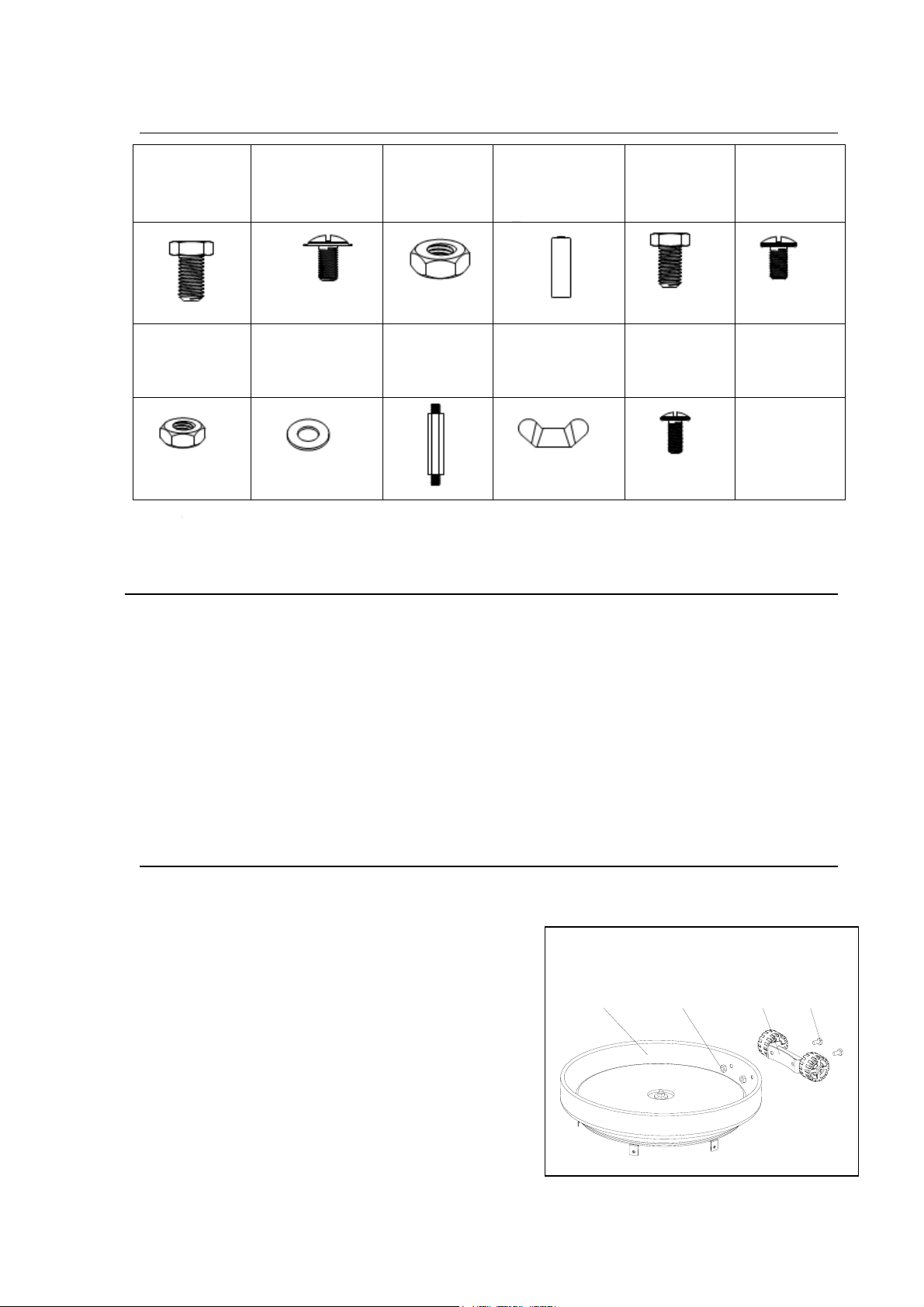
HARDWARE CONTENTS
PREPARATION
Before beginning assembly of product, make sure all parts are present. Compare parts
with package contents list and diagram above. If any part is missing or damaged, do not
attempt to assemble the product. Contact customer service for replacement parts.
Estimated Assembly Time: 30 minutes
Tools required: Adjustable open wrench, Magnetic Head Phillips Screwdriver (Not
included)
ASSEMBLY INSTRUCTIONS
Fig.1
1, With the base (J) upside down, attach wheel
assembly (I) using M8 x 15 mm bolts (AA) and
M8 nuts (CC)
AA. M8*15 mm
Bolt
QTY: 2 pcs
BB. M5*8 mm
Black Bolt
QTY: 8 pcs
CC.M8 Nut
QTY: 2 pcs
DD. AAA
Battery
QTY: 1pc
EE. M6*10
mm Bolt
QTY: 4 pcs
FF. M5*8 mm
Silver Bolt
QTY: 12 pcs
GG. M5 Nut
QTY:12 pcs
HH. M5 Washer
QTY: 12 pcs
II. Reflector
Spacer
QTY:3 pcs
JJ. Wing Nut
QTY:3 pcs
KK. M4*12
mm Bolt
QTY: 4pcs
JCC
A
A
I
10
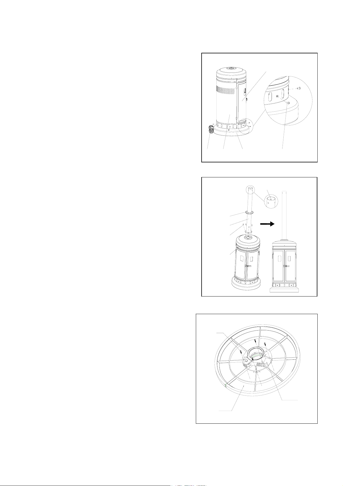
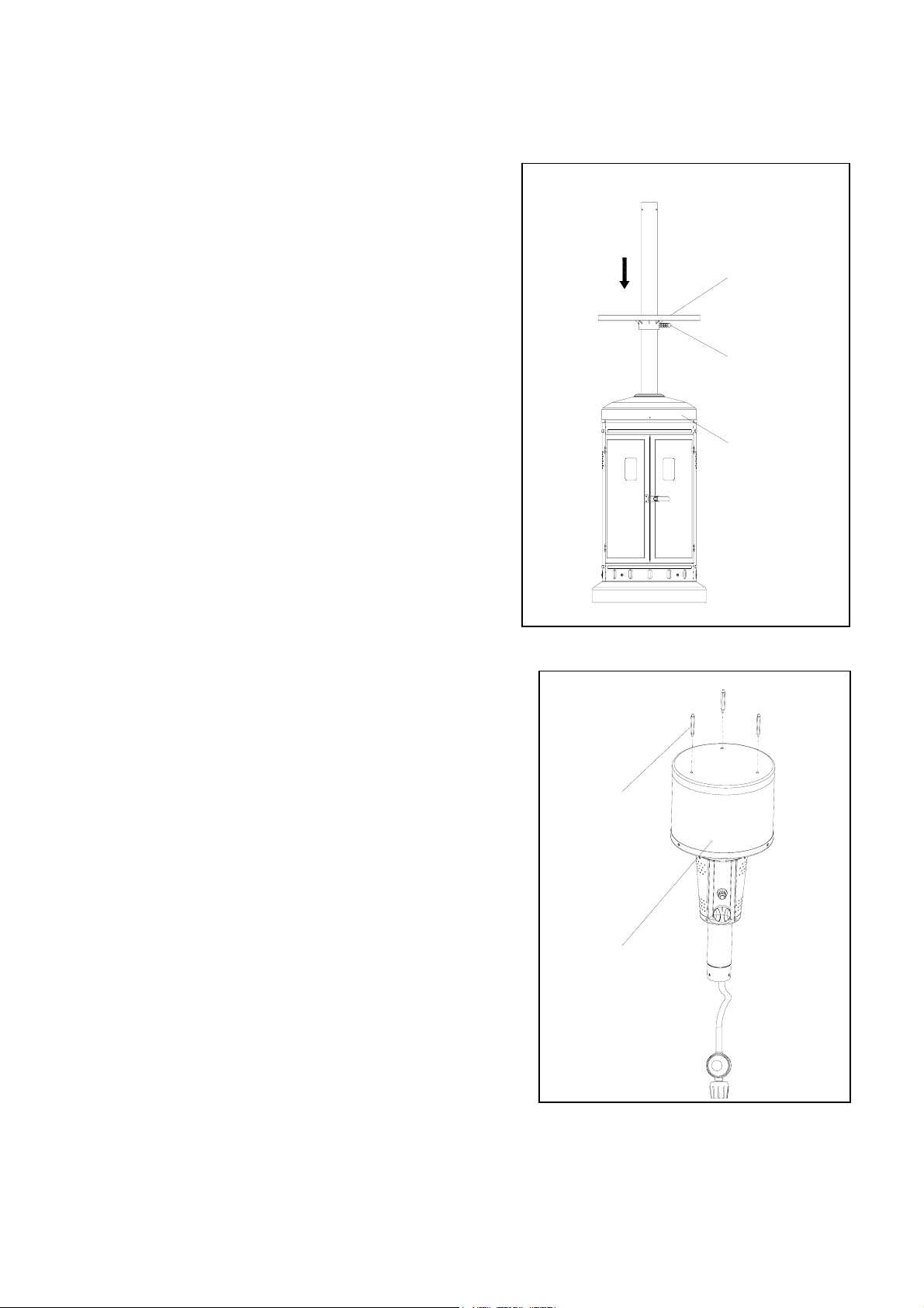
Fig.2
2, Turn the base (J) right-side up, then attach cylinder
assembly (H) using M5 x 8 mm black bolts (BB)
though preassembled L-pins.
Note: The door on the cylinder assembly (H)
should be on the opposite side of the wheel
assembly (I).
Fig.3
Fig.4
3, Attach pole assembly (G) to cylinder assembly (H)
using M6 x 10 mm bolts (EE).
Note: Ensure the pole assembly (G) is straight.
Then, use deck ring (F) to cover connection.
4, Attach table support assembly (E) to table
assembly (D) with M4 x 12 mm Bolt (KK).
Door
IHBB
J
Back
F
G
H
EE
KK
E
D
11
Fig. 5
Fig. 6
5. Unlock the handle on table support assembly
(E), then insert table assembly onto pole (G).
Once the desired height is achieved, turn the
handle clockwise to re-lock table support (E).
6. Insert reflector spacers (II) into the top of
burnerassembly (C).
D
E
G
II
C

12
Fig.7
Fig.8
7. Thread the regulator assembly preassembled
to burner assembly (C) through the pole
assembly (G). Once the burner assembly (C)
rests on pole assembly (G), secure with M5 x
8 mm black bolts (BB).
8. Attach KD domes (B) using M5 nuts
(GG), M5 washers (HH) and M5 x 8 mm
silver bolts (FF). Then, complete dome
assembly by attaching top dome (A) to
KD domes (B) using M5 nuts (GG), M5
washers (HH) and M5 x 8 mm silver bolts
(FF).
C
G
BB
B
GG
HH
FF
GG
HH
FF
A

13
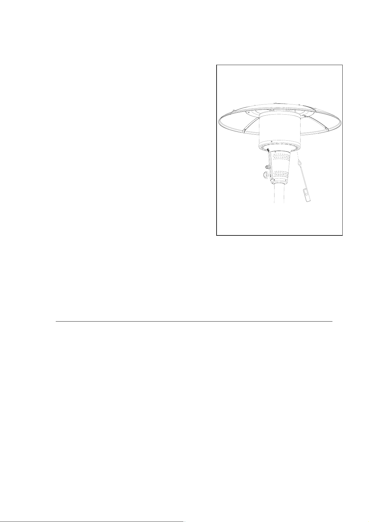
Fig.9
Fig.10
9. Attach dome assembly to burner assembly
(C) by securing wing nuts (JJ) to reflector
spacers (II)
10. Connect the preassembled regulator
assembly from burner assembly (C) to a
20-lb. LP-gas cylinder (sold separately).
Line up threads on cylinder fitting with
those on regulator and rotate clockwise
until tight. HAND TIGHTEN ONLY. DO
NOT USE ANY HAND TOOLS TO MAKE
THIS CONNECTION. Be careful not to
cross threads when screwing in fitting.
To disconnect the LP-gas cylinder, first make
sure the cylinder valve is in the "OFF"
position. Then, turn the knob on the
regulator assembly counterclockwise until it
is loose.
Warning
Before connecting, be sure there is no debris
caught in the head of the LP-gas cylinder
regulator valve or in the head of the burner
and burner ports
JJ
II
C

14
Fig.11
Fig.12
12. To install the battery Size “AAA” (DD),
unscrew the igniter cap preassembled to
burner assembly (C). Insert battery (DD)
into the igniter, ensuring the positive "+"
end faces outward. Then replace the
igniter cap
11. Attach strap inside of cylinder assembly (H)
to secure cylinder. Then close door on
cylinder assembly (H) to complete
installation.
H
+
-
C Igniter
Battery

15
OPERATING INSTRUCTIONS
Fig. 13
Checking for Leaks
Your patio heater has been checked at all factory connections for leakage. To check the
connection at the gas hose/regulator/cylinder:
a. Make leakage solution by mixing 1 part liquid dish soap and 3 part water.
b. Spoon or brush several drops (or use squirt bottle) of the solution onto the gas
hose/regulator and regulator/cylinder and hose connection.
c. Turn on gas cylinder valve. Inspect the connections and look for bubbles.
1. If no bubbles appear, the connection is safe.
2. If bubbles appear, there is leakage. Loosen and re-tighten this connection. If it still
leaks, please call customer service at: 1-855-CHANT-US (1-855-242-6887).
Lighting Instructions
1. Turn the LP gas tank valve OFF. Push the control
knob in, turn OFF, and wait 5 minutes for any
gas to clear.
2. Turn the tank valve ON. Push control knob in
and rotate to PUSH. And, push the igniter button
until the burner is ignited. If igniting the burner
for 5 seconds continuously but the burner fails to
remain lit or becomes extinguished, repeat step
2 after 5 minutes. Complete shutoff period
before relighting.
3. Once the burner has lit, continue to hold the
control knob in for 30 seconds, and then
release.
4. Turn the control knob from HIGH to LOW to the
desired heat setting.
For complete shutdown
1. Please turn the knob to “PUSH” position first, then
push and turn to “Off” position for complete shut
off.
2. Turn the LP gas tank valve OFF before remove the
LP gas tank.
PUSH/HIGH
OFF
LOW
push
Igniter
16
Fig.14
CARE AND MAINTENANCE
To obtain the best performance from your heater make sure you perform the following
maintenance activities on a regular basis:
a. Abrasive cleaners will damage this product.
b. Never use oven cleaner to clean any part of heater.
c. Do not clean any heater part in a self-cleaning oven. The extreme heat will damage
the finish.
d. More frequent cleaning may be required as necessary. It is imperative that control
compartment, burners and circulating air passageways of the heater be kept clean.
e. Spiders and insects can create a dangerous condition that may damage heater or
make it unsafe. Keep burner area clean of all spiders, webs or insects. Clean burner
holes by using a heavy-duty pipe cleaner. Compressed air may help clear away
smaller particles.
f. Inspect heater before each use.
g. Have heater inspected annually and repairs should be made by a qualified service
person.
h. Check heater immediately if any of the following conditions exist.
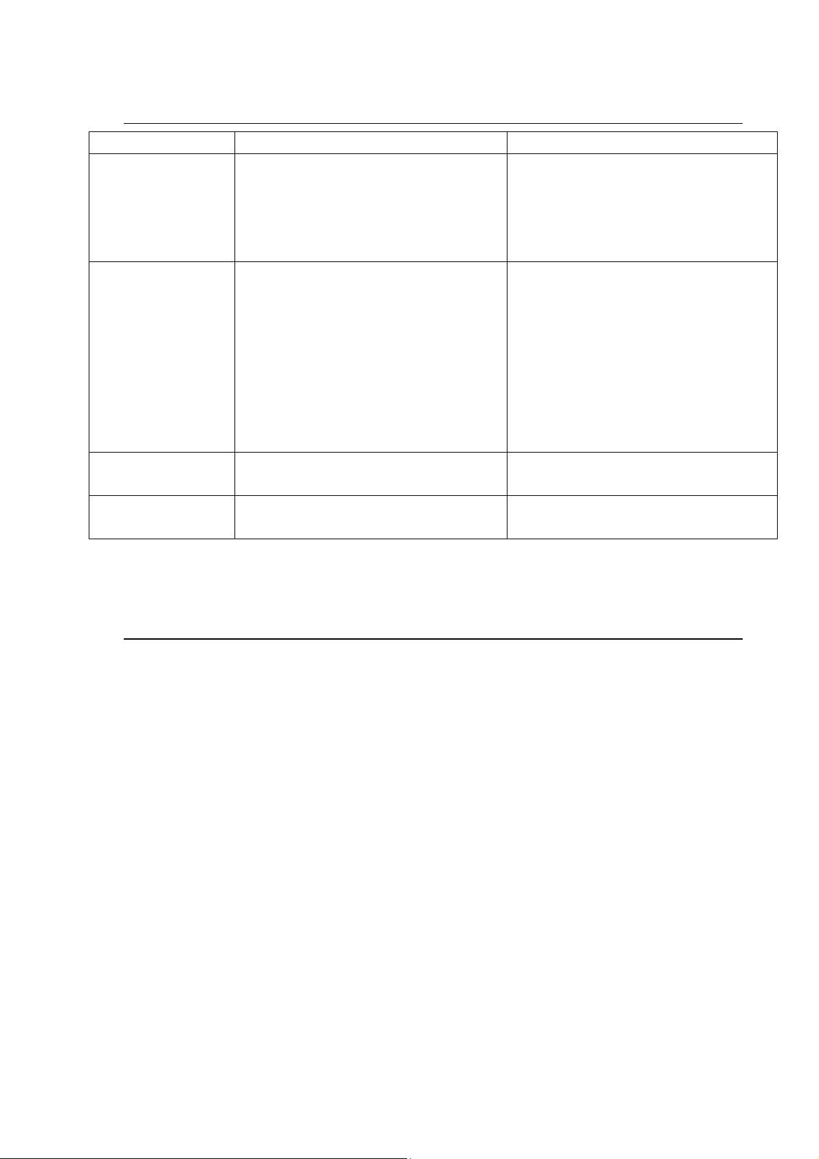
Fig.16
In any case of failure of normal ignition, please
use the lighter (sold separately) to reach the
burner for ignition through the hole on the
bottom of burner diffuser.
WARNING
FOR YOUR SATETY:
If at any time you are unable to light burner
and smell gas, wait 5 minutes to allow gas to
dissipate before attempting to light heater.
WARNING
FOR YOUR SATETY:
DO NOT touch or move heater for at least 45
minutes after use. Allow emitter and dome to
cool before touching.
CAUTION:
Avoid inhaling fumes emitted from the heater’s
first use. Smoke and odor from the burning of
oils used in manufacturing will appear. Both
smoke and odor will dissipate after
approximately 30 minutes. The heater should
NOT produce thick black smoke.

17
1. The smell of gas in conjunction with extreme yellow tipping of burner flames.
2. Heater does not reach proper temperature.
3. Heater’s glow is excessively uneven.
4. Burner makes popping noises during use.
Note: A slight pop is normal when burner is extinguished.
i. Carbon deposits may create a fire hazard. Keep dome and emitter clean at all times.
j. Do not clean heater with combustible or corrosive cleaners. Use warm, soapy water.
k. Do not paint engine, engine access panel or dome.
l. This heater should be thoroughly cleaned on a regular basis.
m. After a period of storage and/or non use, check for leaks, burner obstructions and
inspect for any abrasion, wear, cuts to the hose.
Cleaning
a. Wipe surfaces clean with mild dish detergent or baking soda.
b. For stubborn surfaces use a citrus-based degreaser and a nylon scrubbing brush.
c. Rinse clean with water.
Note: While cleaning the unit, be sure to keep the area around the burner and pilot
assembly dry at all times. Do not submerge the control valve assembly. If the gas
control is submerged in water, do NOT use it. It must be replaced.
TIP: Use high-quality automobile wax to help maintain the appearance of the
heater. Apply to exterior surfaces from the pole down. Do not apply to emitter
screen or domes
Maintenance
a. Keep exterior surfaces clean.
b. Air flow must be unobstructed. Keep controls, burner and circulating air
passageways clean.
Signs of possible blockage include:
Gas odor with extreme yellow tipping of flame.
Heater does NOT reach the desired temperature.
Heater glow is excessively uneven.
Heater makes popping noises.
Note: In a salt-air environment (such as near an ocean) corrosion occurs more quickly
than normal. Frequently check for corroded areas and repair them promptly.
Storage
Between uses or during periods of extended inactivity:
a. Turn control knob to "OFF".
b. Disconnect LP cylinder and move to a secure, well-location outdoors.
c. Store heater upright in an area sheltered from direct contact with inclement weather
(such as rain, sleet, hail, snow, dust and debris).
Note: Never leave LP gas tank exposed to direct sunlight or excessive heat.
d. If desired, use cover (K) to protect the heater and help prevent buildup in air
passages.
CAUTION: Wait until heater is cool before covering.
18
TROUBLESHOOTING
Problem Possible Cause Corrective Action
Burner won’t light 1. Gas pressure is low.
2. The orifice is blocked.
3. Control knob is not in “PUSH”
position.
1. Turn tank valve “OFF” and replace
the tank
2. Clear blockage.
3. Turn control knob to “PUSH”
position.
Burner flame is low 1. Gas pressure is low.
2. The control knob is not positioned
at “High”.
3. The burner jet may be partially
blocked.
4. Outdoor temperature is less than
40°F and tank is less than 1/4 full.
5. Supply hose is bent or kinked.
1. Turn the gas cylinder valve “OFF”
and replace the cylinder.
2. Position the control knob at “High”
3. Clear blockage.
4. Use a full tank.
5. Straighten the hose.
Carbon build-up Build-up of carbon can accumulate
over time.
Wipe off before lighting.
Thick black smoke Blockage in burner Remove blockage and clean burner
inside and outside.
ONE-YEAR LIMITED WARRANTY
The appliance has been manufactured under the highest standards of quality and
workmanship. We warrant to the original consumer/purchaser that all aspects of this
product will be free of defects in material and workmanship for one (1) year from the date of
purchase. A replacement for any defective part will be supplied free of charge for installation
by the consumer. Defects or damage caused by the use of other than genuine parts are not
covered by this warranty. The warranty shall be effective from the date of purchase as shown
in the purchaser’s receipt. This warranty is valid for the original consumer purchaser only
and excludes industrial, commercial or business use of the product, product damage due to
shipment or failure which results from alteration, product abuse or product misuse, where
performed by a container, service company or consumer. We will not be responsible for
labor charges and/or damage incurred in installation, repair or replacement, nor for
incidental or consequential damage. This warranty gives you specific legal rights, and you
may also have the other rights that vary from state to state.
If you experience any problems with your heater, DO NOT RETRURN THE PRODUCT TO THE
STORE, please call 1-855-CHANT-US (1-855-242-6887) for assistances. 8 am to 5 pm
Eastern time, Monday to Friday.
Distributed by Kmart Corporation, Hoffman Estates, IL 60179
If problems cannot be corrected by using these methods, pleas contact 1-855-CHANT-US
(1-855-242-6887 for assistance).

Table of contents
Popular Patio Heater manuals by other brands

Ty Pennington
Ty Pennington Style PG-TTH003 Use and care guide

Mobiclinic
Mobiclinic Nilo user manual

Belleze
Belleze 014-HG-PH00 owner's manual

Veltron
Veltron ZHQ2070-TR instruction manual

Sure Heat
Sure Heat T35PHLP use and care manual

Changzhou Gardensun Furnace
Changzhou Gardensun Furnace HSS-NG-SS owner's manual

Lifestyle
Lifestyle BYH-A-01 instruction manual

MrHeater
MrHeater SunRite MH48PH Operating instructions and owner's manual

Firesense
Firesense Mojave Sun IR 60253 owner's manual

Firesense
Firesense LIP-10-TGG A2 LED 60951 Assembly and care instructions

Firesense
Firesense LIP-10A-TGG-LPG-BU user manual

BlueRhino
BlueRhino Endless Summer 163000 owner's manual


