Esska PILOT TERRA User manual

Betriebsanleitung / Operating Instructions
Mode d’emploi / Instrucciones de Servicio
Инструкция по эксплуатации / 使用说明书
Spritzpistole / Spray gun / Pistolet de pulvérisation
Pistola de pulverización / Пистолет-распылитель / 喷枪
PILOT TERRA
REV. 06/15

32
10
5.3
5.2
8
4
3.1
2
1
5.1
3.3
6
5.5
5.4
7
3.4
13
3.2
11
PILOT TERRA Materialanschluss / Material Connection /
raccordement matière / toma de material / Патрубок для
материала / 物料连接
Stand: August 2014
PILOT TERRA Fließbecher / Gravity-Feed Cup /
à godet gravité / depósito de gravedad /
Наливной стаканчик / 喷壶
12
10
5.3
5.2
8
4
3.1
2
1
3.3
6
5.5
5.4
7
3.4
5.1
9
3.2
11

Seite 6 - 18
Page 20 - 32
Page 34 - 46
Página 48 - 60
Cтрани
ца 62 - 74
页码 76 - 88

76
EG-Konformitätserklärung
Wir, der Gerätehersteller, erklären in alleiniger Verantwortung, dass das Produkt
in der untenstehenden Beschreibung den einschlägigen grundlegenden Sicherheits-
und Gesundheitsanforderungen entspricht. Bei einer nicht mit uns abgestimmten
Änderung an dem Gerät oder bei einer unsachgemäßen Verwendung verliert diese
Erklärung ihre Gültigkeit.
Hersteller WALTHER Spritz- und Lackiersysteme GmbH
Kärntner Str. 18 - 30
D - 42327 Wuppertal
Tel.: +49(0)202 / 787 - 0
Fax: +49(0)202 / 787 - 2217
Typenbezeichnung Handspritzpistolen PILOT TERRA
PILOT TERRA Fließbecher V 11 801
PILOT TERRA Materialanschluss V 11 802
PILOT TERRA-LVLP Fließbecher V 11 811
PILOT TERRA-LVLP Materialanschluss V 11 812
Verwendungszweck Verarbeitung spritzbarer Materialien
Angewandte Normen und Richtlinien
EG-Maschinenrichtlinien 2006 / 42 / EG
94 / 9 EG (ATEX Richtlinien)
DIN EN ISO 12100 Teil 1
DIN EN ISO 12100 Teil 2 DIN EN 1953
DIN EN 1127-1 DIN EN 13463-1
Spezifikation im Sinne der Richtlinie 94 / 9 / EG
Kategorie 2 Gerätebezeichnung II 2 G c T 6 Tech.File,Ref.:
2417
Bevollmächtigt mit der Zusammenstellung der technischen Unterlagen:
Nico Kowalski, WALTHER Spritz- und Lackiersysteme GmbH, Kärntner Str. 18 - 30
D- 42327 Wuppertal
Besondere Hinweise :
Das Produkt ist zum Einbau in ein anderes Gerät bestimmt. Die Inbetriebnahme ist
so lange untersagt, bis die Konformität des Endproduktes mit der Richtlinie
2006 / 42 / EG festgestellt ist.
Wuppertal, den 01. April 2014
Name: Torsten Bröker
Stellung im Betrieb: Leiter der Konstruktion und Entwicklung
Diese Erklärung ist keine Zusicherung von Eigenschaften im Sinne der Produkthaftung. Die
Sicherheitshinweise der Produktdokumentation sind zu beachten.
ppa.
Inhaltsverzeichnis
Explosionszeichnung 2
Konformitätserklärung 7
Ersatzteilliste 8
1 Allgemeines 10
1.1 Kennzeichnung des Modells 10
1.2 Bestimmungsgemäße Verwendung 10
1.3 Sachwidrige Verwendung 11
2 Technische Beschreibung 11
3 Sicherheitshinweise 11
3.1 Kennzeichnung der Sicherheitshinweise 11
3.2 Allgemeine Sicherheitshinweise 12
4 Versorgungsleitungen anschließen 13
5 Inbetriebsetzen und Bedienung 13
6 Spritzbild verändern 14
6.1 Mängel eines Spritzbildes beheben 15
7 Fehlersuche und -beseitigung 15
8 Umrüstung und Instandsetzung 16
9 Reinigung 17
10 Entsorgung 18
11 Technische Daten 18
98
Düsen- / Nadel - Sets
Düsen- / Nadel-Sets bestehen aus Materialdüse, Nadelpackung komplett,
Materialnadel komplett und Nadelfeder (Pos. 3).
Artikel-Nr.
PILOT TERRA Fließbecher V 15 118 03 XX3*
PILOT TERRA Materialanschluss V 15 118 13 XX3*
Düsenausstattung nach Wahl:
▪ 1,0 ▪ 1,4 ▪ 1,8 mm ø
Luftventil - Sets
WALTHER hält für die Handspritzpistolen PILOT TERRA Fließbecher und
PILOT TERRA Materialanschluss Luftventil-Sets bereit, die folgende Artikel
beinhalten:
Ventilschaftdichtung, Ventilkegel komplett, Ventilfeder, Unterlegscheibe, und
O-Ring (Pos. 5).
Artikel-Nr.
PILOT TERRA Fließbecher V 17 118 01 000
PILOT TERRA Materialanschluss V 17 118 02 000
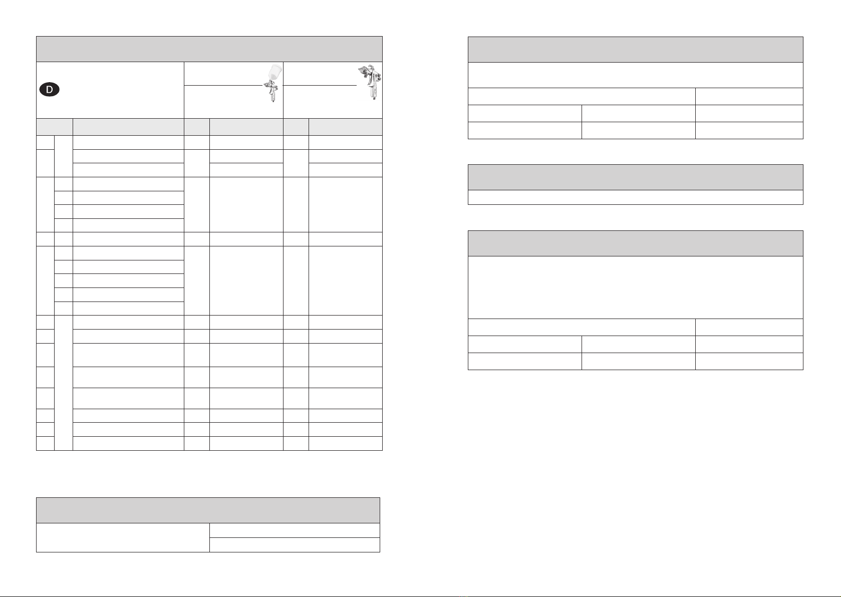
Ersatzteilliste
PILOT TERRA
Fließbecher
PILOT TERRA
Materialanschluss
V 11 801 03 XX3
V 11 811 03 XX3 (LVLP)
V 11 802 03 XX3
V 11 812 03 XX3 (LVLP)
Pos. Bezeichnung Stck Artikelnummer Stck Artikelnummer
1Luftkopfmutter kompl. 12337082 12337082
2Luftkopf 1V 11 801 40 006 1V 11 801 40 006
Luftkopf (LVLP) V 11 801 45 1MP V 11 801 45 1MP
3
3.1 Materialdüse*
1V 15 118 03 XX3* 1V 15 118 13 XX3*
3.2 Nadelpackung kompl.
3.3 Materialnadel kompl.*
3.4 Nadelfeder
4Pistolenkörper kompl. 12337094 12337105
5
5.1 Ventilschaftdichtung
1V 17 118 01 000 1V 17 118 02 000
5.2 Ventilkegel kompl.
5.3 Ventilfeder
5.4 Unterlegscheibe
5.5 O-Ring
6 Federbuchse 1 2337086 12337086
7 Einstellschraube 1 2337087 12337087
8Rund- / Breitstrahlregelung
kompl. 1V 11 801 05 000 1V 11 802 05 000
9Doppelnippel
(Materialanschluss) --1V 00 101 04 000
10 Doppelnippel
(Luftanschluss) 1V 00 101 01 000 1V 00 101 01 000
11 Abzug kompl. 1V 11 801 07 000 1V 11 801 07 000
12 Pistolenschlüssel 1 2342434 12342434
13 Fließbecher kompl. 1V 00 130 00 100 --
* Bei Ersatzteil-Bestellung bitte entsprechende Größe angeben.
Zubehör
WALTHER PILOT Pistolenfett
(Kissen 8 - 10 g)
Artikelnummer
V 00 000 00 001

1110
1 Allgemeines
1.1 Kennzeichnung des Modells
Modell: Handspritzpistole PILOT TERRA
Typ: PILOT TERRA Fließbecher V 11 801
PILOT TERRA Materialanschluss V 11 802
PILOT TERRA-LVLP Fließbecher V 11 811
PILOT TERRA-LVLP Materialanschluss V 11 812
Hersteller: WALTHER Spritz- und Lackiersysteme GmbH
Kärntner Str. 18-30
D-42327 Wuppertal
Tel.: +202 / 787-0
Fax: +202 / 787-2217
1.2 Bestimmungsgemäße Verwendung
Die Handspritzpistolen PILOT TERRA Fließbecher sowie PILOT TERRA
Materialanschluss dienen ausschließlich der Verarbeitung spritzbarer Medien, wie
z.B.:
• Lacke und Farben
• Fette, Öle und Korrosionsschutzmittel
• Keramikglasuren
Aggressive Materialien dürfen nicht verspritzt werden.
Sind die Materialien, die Sie verspritzen wollen, hier nicht aufgeführt, wenden Sie sich
bitte an WALTHER Spritz- und Lackiersysteme GmbH, Wuppertal.
Die spritzbaren Materialien dürfen lediglich auf Werkstücke bzw. Gegenstände aufge-
tragen werden.
Die Temperatur des Spritzmaterials darf 43°C grundsätzlich nicht überschreiten. Die
bestimmungsgemäße Verwendung schließt auch ein, dass alle Hinweise und
Angaben der vorliegenden Betriebsanleitung gelesen, verstanden und beachtet
werden.
Das Gerät erfüllt die Explosionsschutz-Forderungen der Richtlinie 94 / 9 EG (ATEX)
für die auf dem Typenschild angegebene Explosionsgruppe, Gerätekategorie, und
Temperaturklasse. Beim Betreiben des Gerätes sind die Vorgaben dieser
Betriebsanleitung unbedingt einzuhalten. Die vorgeschriebenen Inspektions- und
Wartungsintervalle sind einzuhalten. Die Angaben auf den Geräteschildern bzw. die
Angaben in dem Kapitel technische Daten sind unbedingt einzuhalten und dürfen
nicht überschritten werden.
Eine Überlastung des Gerätes muss ausgeschlossen sein. Das Gerät darf in explosi-
onsgefährdeten Bereichen nur nach Maßgabe der zuständigen Aufsichtsbehörde
eingesetzt werden.
Der zuständigen Aufsichtsbehörde bzw. dem Betreiber obliegt die Festlegung
der Explosionsgefährdung (Zoneneinteilung).
Es ist betreiberseitig zu prüfen und sicherzustellen, dass alle technischen Daten und
die Kennzeichnung gemäß ATEX mit den notwendigen Vorgaben übereinstimmen.
Bei Anwendungen, bei denen der Ausfall des Gerätes zu einer Personengefährdung
führen könnten, sind betreiberseitig entsprechende Sicherheitsmaßnahmen vorzu-
sehen.
Falls im Betrieb Auffälligkeiten erkannt werden, muss das Gerät sofort stillgesetzt
werden und es ist mit WALTHER Spritz- und Lackiersysteme Rücksprache zu halten.
Erdung / Potentialausgleich
Es muss sichergestellt werden, dass die Spritzpistole über einen leitfähigen
Luftschlauch ausreichend geerdet ist (maximaler Wiederstand 106 Ω).
1.3 Sachwidrige Verwendung
Die Spritzpistole darf nicht anders verwendet werden, als es im Abschnitt bestim-
mungsgemäße Verwendung geschrieben steht. Jede andere Verwendung ist
sachwidrig. Zur sachwidrigen Verwendung gehören z.B.:
• das Verspritzen von Materialien auf Personen und Tiere.
• das Verspritzen von flüssigem Stickstoff.
2 Technische Beschreibung
PILOT TERRA: Spritzpistole für konventionelle Zerstäubung
PILOT TERRA-LVLP: Spritzpistole spritznebelreduziert
Ausführungen: • mit Fließbecher
• mit Materialanschluss
Bei Betätigung des Abzughebels (Pos. 11) wird zuerst der Ventilkegel (Pos. 5.2)
geöffnet (Vorluft) und dann erst die Materialnadel (Pos. 3.3) zurückgezogen. Das
Schließen erfolgt in umgekehrter Reihenfolge.
Die Materialdurchflussmenge ist abhängig vom Durchmesser der Düse und der
Einstellung des Materialdruckes am Druckgefäß oder Materialdruckregler. Zusätzlich
lässt sich die Materialmenge durch Ein- bzw. Ausschrauben der Stellschraube
(Pos. 7) regeln.
3 Sicherheitshinweise
3.1 Kennzeichnung der Sicherheitshinweise
Warnung
Das Piktogramm und die Dringlichkeitsstufe “Warnung“ kennzeichnen eine mögliche
Gefahr für Personen. Mögliche Folgen: schwere oder leichte Verletzungen.
Achtung
Das Piktogramm und die Dringlichkeitsstufe “Achtung“ kennzeichnen eine mögliche
Gefahr für Sachwerte. Mögliche Folgen: Beschädigung von Sachen.
1312
Hinweis
Das Piktogramm und die Dringlichkeitsstufe “Hinweis“ kennzeichnen zusätzliche
Informationen für das sichere und effiziente Arbeiten mit der Spritzpistole.
3.2 Allgemeine Sicherheitshinweise
► Die einschlägigen Unfallverhütungsvorschriften sowie die sonstigen anerkann-
ten sicherheitstechnischen und arbeitsmedizinischen Regeln sind einzuhalten.
►Benutzen Sie die Spritzpistole nur in gut belüfteten Räumen. Im Arbeitsbereich
ist Feuer, offenes Licht und Rauchen verboten. Beim Verspritzen leichtentzünd-
licher Materialien (z. B. Lacke, Kleber, Reinigungsmittel usw.) besteht erhöhte
Gesundheits-, Explosions- und Brandgefahr.
►Es muss sichergestellt werden, dass die Spritzpistole separat oder in Verbindung
mit dem Gerät auf dem sie aufgebaut ist, ausreichend geerdet ist
(
max. Widerstand
106Ω).
►Schalten Sie vor jeder Wartung und Instandsetzung die Luft- und Materialzufuhr
zur Spritzpistole drucklos - Verletzungsgefahr.
► Halten Sie beim Verspritzen von Materialien keine Hände oder andere
Körperteile vor die unter Druck stehende Düse der Spritzpistole
- Verletzungsgefahr.
► Richten Sie die Spritzpistole nicht auf Personen und Tiere - Verletzungsgefahr.
►Beachten Sie die Verarbeitungs- und Sicherheitshinweise der Hersteller von
Spritzmaterial und Reinigungsmitteln. Insbesondere aggressive und ätzende
Materialien können gesundheitliche Schäden verursachen.
►Tragen Sie im Arbeitsbereich der Spritzpistole einen Gehörschutz. Der erzeugte
Schallpegel der Spritzpistole von ca. 86 dB (A) kann einen Gehörschaden
verursachen.
►Die partikelführende Abluft ist vom Arbeitsbereich und Betriebspersonal fernzu-
halten. Tragen Sie dennoch vorschriftsgemäßen Atemschutz und vorschriftsge-
mäße Arbeitskleidung, wenn Sie mit der Spritzpistole Materialien verarbeiten.
Umherschwebende Partikel gefährden Ihre Gesundheit.
►Achten Sie stets darauf, dass nach den Montage- und Wartungsarbeiten alle
Muttern und Schrauben fest angezogen sind.
►Verwenden Sie nur Original-Ersatzteile, da WALTHER nur für diese eine siche-
re und einwandfreie Funktion garantieren kann.
► Bei Nachfragen zur gefahrlosen Benutzung der Spritzpistole sowie der darin
verwendeten Materialien, wenden Sie sich bitte an WALTHER Spritz- und
Lackiersysteme GmbH, D-42327 Wuppertal.
4 Versorgungsleitungen anschließen
Warnung
Luftschläuche, die mit einer Schlauchtülle befestigt werden, müssen zusätzlich mit
einer Schlauchschelle gesichert sein.
5 Inbetriebnahme / Bedienung
Bevor Sie die Spritzpistole in Betrieb setzen können, müssen folgende Voraus-
setzungen erfüllt sein:
• Der Zerstäuberluftdruck muss an der Spritzpistole anstehen
• Der Materialdruck muss an der Spritzpistole anstehen
Achtung
Der Materialdruck darf nicht höher eingestellt sein als
• 5 bar, da sonst kein funktionssicherer Betrieb der Spritzpistole gewährleistet ist.
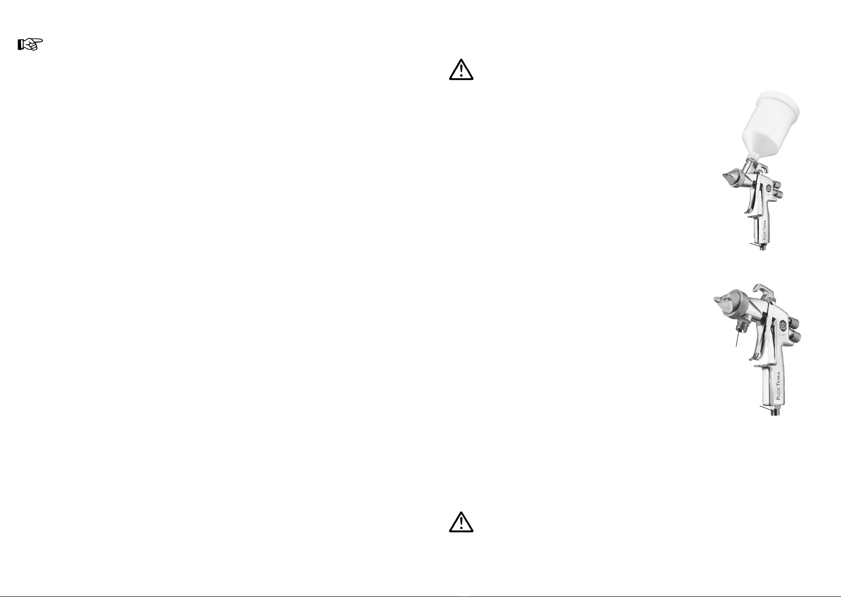
Ausführung: Fließbecher
1. Befestigen Sie den Druckluftschlauch an dem
Luftanschluss (Pos. 10) der Spritzpistole.
2. Befüllen Sie den Fließbecher mit dem zu ver-
spritzenden Material. Verschließen Sie den
Fließbecher.
3. Schalten Sie die Druckluftversorgung ein.
Die Pistole ist nun betriebsbereit.
Ausführung: Materialanschluss
1. Befestigen Sie den Druckluftschlauch an dem
Luftanschluss (Pos. 10) der Spritzpistole.
2. Befestigen Sie den Materialzuführungsschlauch
an dem Materialanschluss (Pos. 9) der
Spritzpistole.
3. Um die im Materialschlauch befindliche Luft
entweichen zu lassen, betätigen Sie den
Abzugshebel solange, bis ein gleichmäßiger
Materialstrahl aus der Düse tritt; nun kann die
Pistole wieder geschlossen werden.
Die Pistole ist nun betriebsbereit. Luftanschluss
Material-
anschluss
Luftanschluss

1514
Warnung
Die Spritzpistole muss nach Arbeitsende immer drucklos geschaltet werden. Die
unter Druck stehenden Leitungen können platzen und nahestehende Personen
durch das ausströmende Material verletzen.
Hinweis
Vor dem ersten Inbetriebsetzen muss die Pistole mit einem geeigneten Lösemittel
gespült werden, um das Spritzmaterial nicht zu verunreinigen.
Spritzbildprobe
Eine Spritzbildprobe sollte immer dann erzeugt werden, wenn:
• die Spritzpistole zum erstenmal in Betrieb gesetzt wird.
• das Spritzmaterial ausgetauscht wird.
• die Pistole zur Wartung oder Instandsetzung zerlegt wurde.
Die Spritzbildprobe kann auf ein Probewerkstück, Blech, Pappe oder Papier abge-
geben werden.
6 Spritzbild verändern
Sie können an der PILOT TERRA durch die folgenden Einstellungen das Spritzbild
verändern:
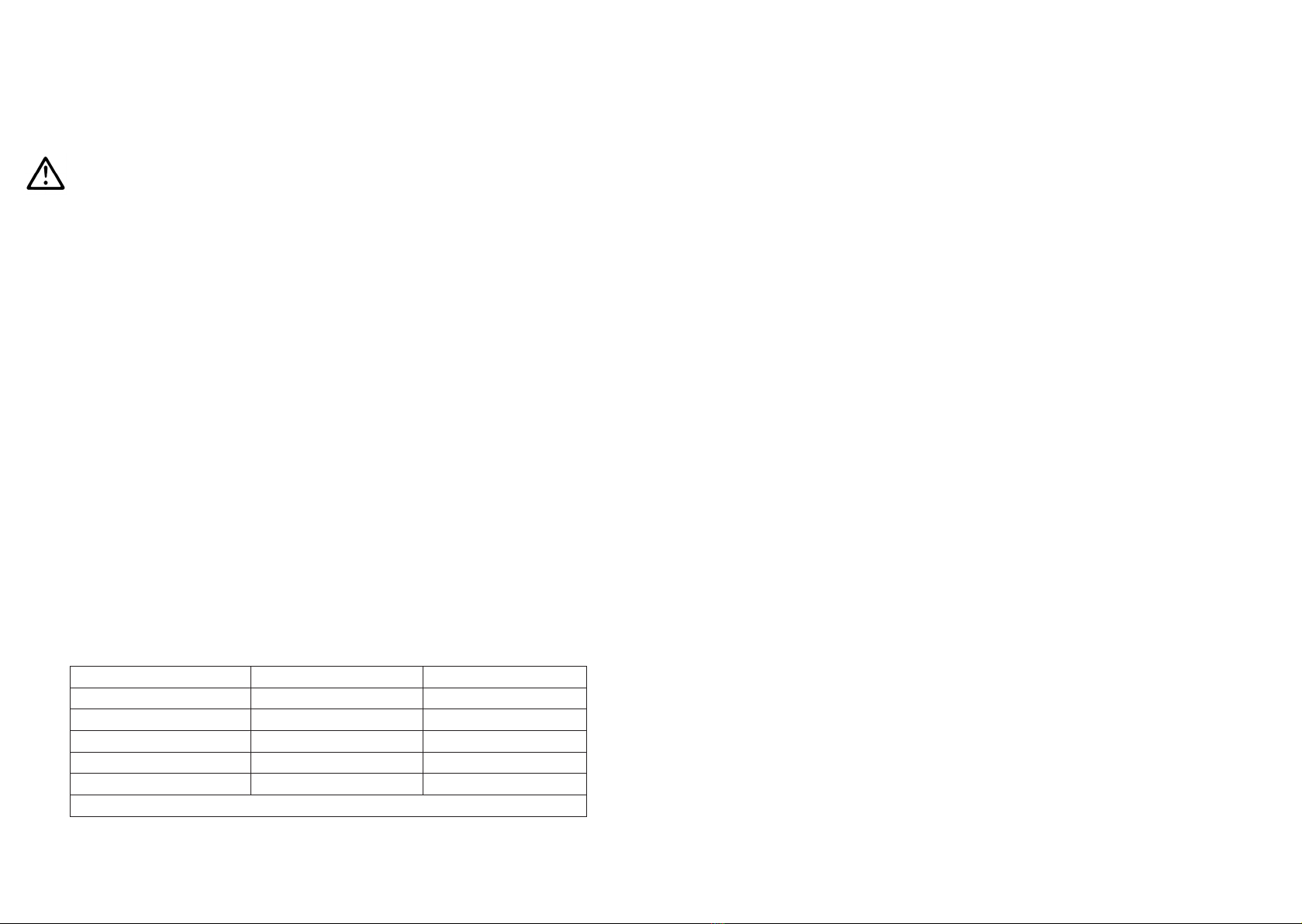
6.1 Mängel eines Spritzbildes beheben
Die folgende Tabelle zeigt Ihnen, mit welchen Einstellungen Sie das Spritzbild beein-
flussen können.
Spritzbildprobe Abweichung erforderliche Einstellung
Spritzbild ist in der Mitte
zu dick
• breitere Spritzstrahlform ein-
stellen
Spritzbild ist an den
Enden zu dick
• rundere Spritzstrahlform ein-
stellen
Spritzbild ist ziemlich
grobtropfig • Zerstäuberluftdruck erhöhen
Materialauftrag ist in der
Spritzbildmitte sehr dünn • Zerstäuberluftdruck verringern
Spritzbild ist in der Mitte
gespalten
• Düsendurchmesser erhöhen
• Zerstäuberluftdruck verringern
• Materialdruck erhöhen
Spritzbild ist sehr ballig • Materialdruck verringern
• Zerstäuberluftdruck erhöhen
7 Fehlersuche und -beseitigung
Warnung
Unterbrechen Sie vor jeder Umrüstung und Instandsetzung die Luftzufuhr zur
Spritzpistole - Verletzungsgefahr.
Fehler Ursache Abhilfe
Pistole tropft
Materialnadel oder -düse ver-
schmutzt bzw.beschädigt
Federbuchse (Pos. 6) zu weit nach
hinten gedreht
• Reinigen bzw. ersetzen
• Etwas einschrauben
(Rechtsdrehen)
Stoßweiser oder
flatternder Spritz-
strahl
zu wenig Material im Fließbecher
Becher wird während des Spritz-
vorgangs zu stark geneigt
Materialdüse lose oder beschädigt
• Material auffüllen
• gerader halten
• festziehen, evtl. ersetzen
Pistole bläst in
Ruhestellung
Ventilfeder (Pos. 5.3) oder
Ventilkegel (Pos. 5.2) beschädigt • austauschen
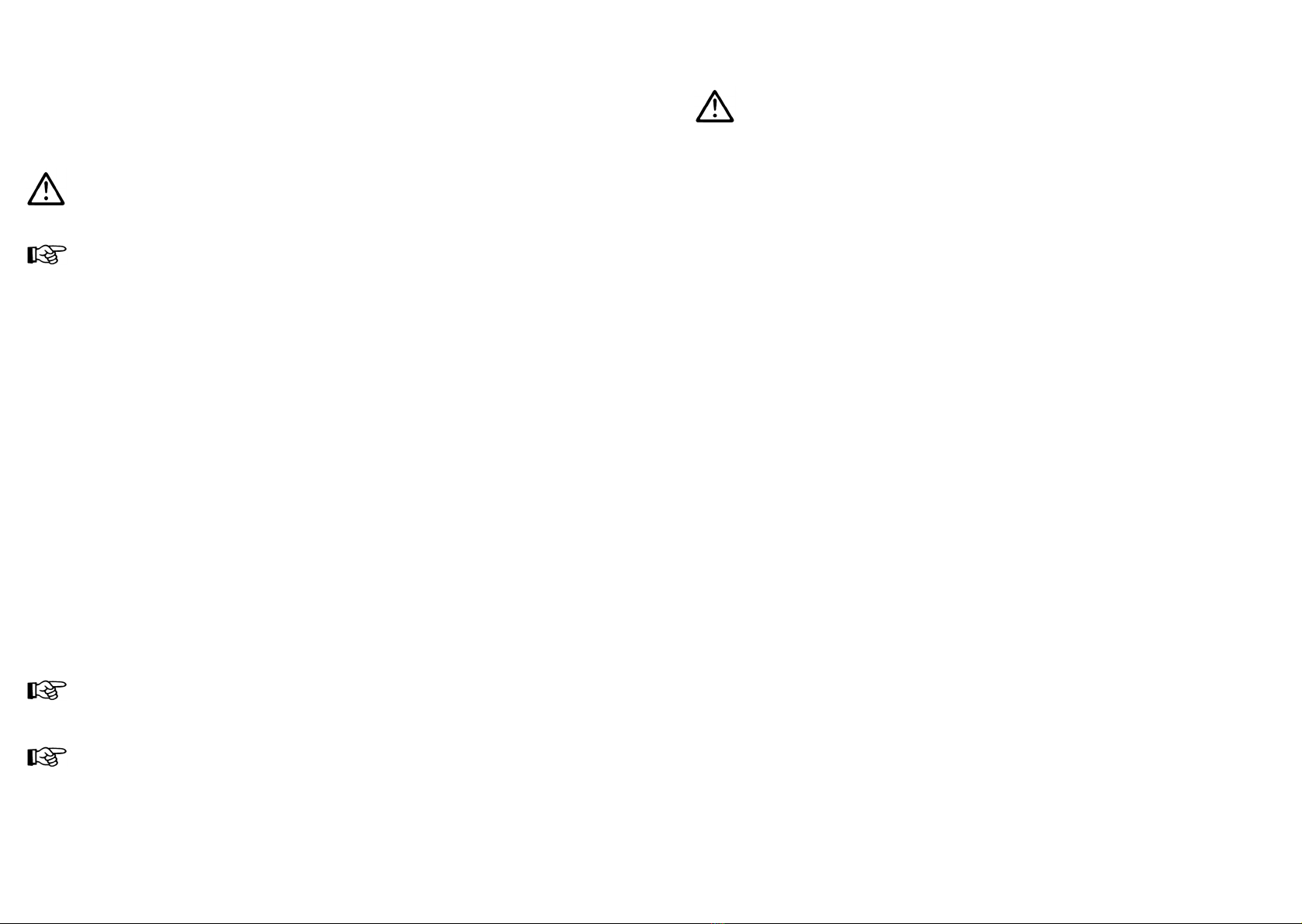
Breit- bzw. Rundstrahl einstellen
Die Regelschraube dient zur Regulierung der
Spritzstrahlbreite. Der Spritzstrahl wird durch
Linksdrehen (Ausschrauben) zum Breitstrahl,
durch Rechtsdrehen (Einschrauben) zum
Rundstrahl.
Materialdurchflussmenge einstellen
Die Materialmenge läßt sich durch Ein- bzw. Aus-
schrauben der Stellschraube regeln. Die
Materialmenge wird durch Linksdrehen
(Ausschrauben) erhöht, durch Rechtsdrehen
(Einschrauben) verringert.
Luftanschluss
Material-
anschluss
angestrebtes Spritzergebnis

1716
8 Umrüstung und Instandsetzung
Wenn Sie das Spritzbild über die bereits erwähnten Möglichkeiten hinaus verändern
wollen, muss die Spritzpistole umgerüstet werden. Die zum Spritzmaterial passende
Luftkopf- / Materialdüse- / Nadel-Kombination bildet eine aufeinander abgestimmte
Einheit - die Düseneinlage. Tauschen Sie immer die komplette Düseneinlage aus,
damit die gewünschte Spritzbildqualität erhalten bleibt.
Warnung
Unterbrechen Sie vor jeder Umrüstung die Luftzufuhr zur Spritzpistole - Verletzungs-
gefahr.
Hinweis
Zur Durchführung der im Folgenden aufgeführten Arbeitsschritte benutzen Sie bitte
die Explosionszeichnung am Anfang dieser Betriebsanleitung.
Materialdüse und Luftkopf wechseln
1. Schrauben Sie die Luftkopfmutter (Pos. 1) ab.
2. Nehmen Sie den Luftkopf (Pos. 2) ab.
3. Schrauben Sie die Materialdüse (Pos. 3.1) mit Schlüssel SW 19 aus dem
Pistolenkörper (Pos. 4) aus.
Die Montage der neuen Düseneinlage erfolgt in umgekehrter Reihenfolge.
Materialnadel wechseln
1. Entfernen Sie die Einstellschraube (Pos. 7).
2. Entnehmen Sie die Nadelfeder (Pos. 3.4).
3. Ziehen Sie die Materialnadel (Pos. 3.3) aus dem Pistolenkörper.
Die Montage erfolgt in umgekehrter Reihenfolge.
Undichte Nadelpackung austauschen
1. Entfernen Sie die Materialnadel wie oben beschrieben.
2. Schrauben Sie die Hebelschaftschraube und die Hebelschraube ab und entfer-
nen Sie den Abzug (Pos. 11).
3. Schrauben Sie die Nadelstopfbuchse aus dem Pistolenkörper aus.
4. Entfernen Sie die Nadelpackung (Pos. 3.2) (Benutzen Sie hierzu evtl. einen
dünnen Draht, dessen Ende zu einem Haken umgebogen ist).
Die Montage erfolgt in umgekehrter Reihenfolge.
Hinweis
Die aus dem Pistolenvorsatz entnommene Nadeldichtung darf nicht wieder verwendet
werden, da sonst eine funktionssichere Dichtwirkung nicht gewährleistet ist.
Hinweis
Alle beweglichen und gleitenden Bauteile (außer Materialnadel) müssen vor dem
Einbau in den Pistolenkörper mit WALTHER PILOT Pistolenfett
(Art.-Nr.: V 00 000 00 001) eingefettet werden.
9 Reinigung
Achtung
Legen Sie die Spritzpistole nie in Lösemittel oder ein anderes Reinigungsmittel. Die
einwandfreie Funktion der Spritzpistole kann sonst nicht garantiert werden.
Verwenden Sie zur Reinigung keine harten oder spitzen Gegenstände. Für Schäden,
die aus unsachgemäßer Reinigung herrühren, übernimmt WALTHER, Wuppertal,
keine Gewährleistung.
Sie können die Spritzpistole reinigen, ohne diese dabei zerlegen zu müssen.
1. Befüllen Sie den gesäuberten Fließbecher mit einem zum verspritzten Material
passenden Reinigungsmittel.
2. Setzen Sie die Spritzpistole in Betrieb.
3. Setzen Sie die Spritzpistole erst außer Betrieb, wenn diese nur noch klares
Reinigungsmittel verspritzt.
Die gesamte Spritzanlage ist bis zum nächsten Einsatz drucklos zu schalten.
Verwenden Sie zur Reinigung der Spritzpistole nur Reinigungsmittel, die vom
Hersteller des Spritzmaterials angegeben werden und die folgenden Bestandteile
nicht enthalten:
• halogenierte Kohlenwasserstoffe (z. B. 1,1,1, Trichlorethan, Methylen-Chlorid
usw.)
• Säuren und säurehaltige Reinigungsmittel
• regenerierte Lösemittel (sog. Reinigungsverdünnungen)
• Entlackungsmittel.
Die o.g. Bestandteile verursachen an galvanisierten Bauteilen chemische Reaktionen
und führen zu Korrosionsschäden.
Reinigen Sie die Spritzpistole
• vor jedem Farb- bzw. Materialwechsel.
• mindestens einmal wöchentlich.
• materialabhängig und je nach Verschmutzungsgrad mehrfach wöchentlich.
Ausführliche Reinigung
1. Zerlegen Sie die Pistole.
2. Reinigen Sie den Luftkopf und die Materialdüse mit einem Pinsel und dem
Reinigungsmittel.
3. Reinigen Sie alle übrigen Bauteile und den Pistolenkörper mit einem Tuch und
dem Reinigungsmittel.
4. Bestreichen Sie folgende Teile mit einem dünnen Fettfilm:
• Nadelfeder
• alle gleitenden Teile und Lagerstellen.
Die beweglichen Innenteile sind wenigstens einmal wöchentlich zu fetten. Die
Federn sollten ständig mit einem leichten Fettüberzug versehen sein. Verwenden Sie
dazu WALTHER PILOT Pistolenfett und einen Pinsel. Anschließend wird die
Spritzpistole in umgekehrter Reihenfolge zusammengesetzt.
18
10 Entsorgung
Die Spritzmedien sowie die bei der Reinigung und Wartung anfallenden Materialien
sind den Gesetzen und Vorschriften entsprechend sach- und fachgerecht zu entsor-
gen.
Warnung
Beachten Sie die Hinweise des Herstellers der Spritz- und Reinigungsmittel.
Unachtsam entsorgtes Material gefährdet die Gesundheit von Mensch und Tier.
11 Technische Daten
Gewicht
PILOT TERRA mit Fließbecher: 530 g
PILOT TERRA mit Materialanschluss: 425 g
Anschlüsse
Spritzluft: G 1/4“
Materialzufuhr: G 3/8“
Düsenausstattung nach Wahl: 1,0 • 1,4 • 1,8 mm ø
Luftköpfe: 6-Loch-Luftkopf
8-Loch-Luftkopf (LVLP)
Druckbereiche
Eingangsluftdruck: max. 8 bar
Materialdruck: max. 5 bar
max. Betriebstemperatur: 43°C
Schallpegel
(gemessen in ca. 1m
Abstand zur Spritzpistole) 83 db (A)
Luftverbrauch:
Zerstäuberluftdruck Rundstrahl in l/min. Breitstrahl in l/min.
1 bar 100 130
2 bar 170 210
3 bar 230 290
4 bar 290 360
5 bar 360 450
Typ LVLP: Bei einem Eingangsdruck von 3,5 bar beträgt der Luftverbrauch 270 l/min.
Technische Änderungen vorbehalten.

2120
Contents
Exploded Drawing 2
Declaration of CE-Conformity 21
Replacement parts 22
1 General 24
1.1 Model identification 24
1.2 Intended use 24
1.3 Inappropriate use 25
2 Technical description 25
3 Safety instructions 25
3.1 Identification of safety instructions 25
3.2 General Safety instructions 26
4 Supply line connection 27
5 Operational Handling 27
6 Spray pattern adjustments 28
6.1 Correcting spray pattern flaws 29
7 Troubleshooting and fault rectification 29
8 Conversion and repair 30
9 Cleaning 31
10 Waste disposal 32
11 Technical Data 32
Declaration of CE-Conformity
We, the manufacturers of the equipment, hereby declare under our sole respon-
sibility that the product(s) described below conform to the essential safety require-
ments. This declaration will be rendered invalid if any changes are made to the equip-
ment without prior consultation with us.
Manufacturer WALTHER Spritz- und Lackiersysteme GmbH
Kärntner Str. 18 - 30
D - 42327 Wuppertal
Tel.: +49(0)202 / 787 - 0
Fax: +49(0)202 / 787 - 2217
Type Designation Manual Spray Guns PILOT TERRA
PILOT TERRA Gravity-Feed Cup V 11 801
PILOT TERRA Material Connection V 11 802
PILOT TERRA-LVLP Gravity-Feed Cup V 11 811
PILOT TERRA-LVLP Material Connection V 11 812
Intended purpose Processing of sprayable media
Applied Standards and Directives
EU-Mechanical Engineering Directives 2006 / 42 / EC
94 / 9 EC (ATEX Directives)
DIN EN ISO 12100-1
DIN EN ISO 12100-2 DIN EN 1953
EN 1127-1 DIN EN 13463-1
Specification according 94 / 9 / EC
Category 2 Part marking II 2 G c T 6 Tech.File,Ref.:
2417
Authorized with the compilation of the technical file:
Nico Kowalski, WALTHER Spritz- und Lackiersysteme GmbH, Kärntner Str. 18 - 30
D- 42327 Wuppertal
Special remarks :
The named product is intended for installation in other equipment. Commissioning is
prohibited until such time as the end product has been proved to conform to the
provision of the Directives 2006 / 42 / EC.
Wuppertal, the 1st of April 2014
Name: Torsten Bröker
Position: Manager, Design and Development
This Declaration does not give assurance of properties in the sense of product liability. The safe-
ty instructions provided in the product documentation must be observed at all times.
p.p.

2322
Replacement Parts
PILOT TERRA
Gravity-feed cup
PILOT TERRA
Material Connection
V 11 801 03 XX3
V 11 811 03 XX3 (LVLP)
V 11 802 03 XX3
V 11 812 03 XX3 (LVLP)
N° Description Qty. Article-No. Qty. Article-No.
1Air cap nut compl. 1 2337082 12337082
2Air cap 1V 11 801 40 006 1V 11 801 40 006
Air cap (LVLP) V 11 801 45 1MP V 11 801 45 1MP
3
3.1 Material nozzle*
1V 15 118 03 XX3* 1V 15 118 13 XX3*
3.2 Needle seal Packing comp.
3.3 Material needle compl.*
3.4 Needle spring
4Gun body compl. 12337094 12337105
5
5.1 Valve shaft seal
1V 17 118 01 000 1V 17 118 02 000
5.2 Valve cone compl.
5.3 Valve spring
5.4 Washer
5.5 O-Ring
6Spring bushing 12337086 12337086
7Adjusting screw 12337087 12337087
8Round/ wide jet adjustment
compl. 1V 11 801 05 000 1V 11 802 05 000
9Double nipple
(Material connection)--1V 00 101 04 000
10 Double nipple
(Air connection)1V 00 101 01 000 1V 00 101 01 000
11 Trigger compl. 1V 11 801 07 000 1V 11 801 07 000
12 Gun key 12342434 12342434
13 Gravity-feed cup compl. 1V 00 130 00 100 --
* When ordering replacements please quote the respective sizes.
Accessories
Walther Pilot gun grease
(Pads 8 - 10 g)
Article-No.
V 00 000 00 001
Nozzle / needle sets
The nozzle / needle sets consist material nozzle, needle seal packing comp., mate-
rial needle compl. and needle spring (No3).
Article-No.
PILOT TERRA Gravity-feed cup V 15 118 03 XX3*
PILOT TERRA Material Connection V 15 118 13 XX3*
Nozzle sizes optional:
▪ 1,0 ▪ 1,4 ▪ 1,8 mm ø
Air valve sets
WALTHER has PILOT TERRA Gravity-feed cup and PILOT TERRA material
connection air valve sets available for the manual spray guns containing the fol-
lowing items:
Valve shaft seal, valve cone compl., valve spring, washer and O-Ring (No 5).
Article-No.
PILOT TERRA Gravity-feed cup V 17 118 01 000
PILOT TERRA Material Connection V 17 118 02 000

2524
equipment in accordance with ATEX are compliant with the necessary requirements.
The operator must provide corresponding safety measures for all applications in
which the breakdown of the equipment might lead to danger to persons.
If any irregularities are observed while the equipment is in operation, the equipment
must be put out of operation immediately and WALTHER Spritz- und Lackiersysteme
must be consulted.
Grounding / Equipotential Bonding
Measures must be taken to ensure that the spray gun is sufficiently grounded
(earthed) by means of a conductive air hose (maximum resistance 106Ω).
1.3 Inappropriate use
The spray gun can’t be used for any application not included in the instructions. Any
other use is improper. Some sample of improper use:
• Spray in direction of people or animals
• Spray liquid nitrogen
2 Technical Description
PILOT TERRA: Manual spray gun for conventional atomisation
PILOT TERRA-LVLP: Manual spray gun vapour-reduced
Model versions: • with gravity-feed cup
• with material connection
When pulling the trigger (No11) the valve cone opens first (No5.2) (pre-air) and the
material needle (No3.3) is pulled back only after this. Closing takes place in reverse
order.
The material flow rate is dependent on the diameter of the nozzle and the adjustment
of the material pressure at the pressure tank or material pressure regulator. In addi-
tion, the material flow rate can be controlled by screwing the adjusting screw (N° 7)
in or out.
3 Safety instructions
3.1 Identification of safety instructions
Warning
The pictogram and the urgency level “Warning“ identify a possible danger to
persons.
Possible consequences: Slight to severe injuries.
Attention
The pictogram and the urgency level “Attention“ identify a possible danger to
material assets.
Possible consequences: Damage to material assets.
1 General
1.1 Model Identification
Model: Manual Spray Gun PILOT TERRA
Type: PILOT TERRA Gravity-Feed Cup V 11 801
PILOT TERRA Material Connection V 11 802
PILOT TERRA-LVLP Gravity-Feed Cup V 11 811
PILOT TERRA-LVLP Material Connection V 11 812
Manufacturer: WALTHER Spritz- und Lackiersysteme GmbH
Kärntner Str. 18-30
D-42327 Wuppertal
Tel.: +202 / 787-0
Fax: +202 / 787-2217
1.2 Intended use
The manual spray guns PILOT TERRA Gravity-Feed Cup and PILOT TERRA
Material Connection are designed to be used exclusively for sprayable media, such
as:
• paints and lacquers
• greases, oils and corrosion preventives
• ceramic glazes
Aggressive materials must not be sprayed.
If the material you intend to spray is not included in the above list, please contact
WALTHER Spritz- und Lackiersysteme GmbH, Wuppertal, for further information.
Please note that sprayable materials may only be applied to workpieces and /or
similar objects.
The temperature of the spraying material must not exceed 43°C.
The term "normal use” also implies that all safety warnings, operating handling
details, etc., as stated in these operating instructions are carefully read, understood
and duly complied with.
This equipment complies with the explosion protection requirements of Directive
94/9/EC (ATEX) for the explosion group, equipment category and temperature class
indicated on the type plate. When using the equipment, the requirements specified
in these Operating Instructions must be observed at all times.
The technical data indicated on the equipment rating plates and the specifications in
the chapter "Technical Data" must be complied with at all times and must not be
exceeded. An overloading of the equipment must be ruled out.
The equipment may be used in potentially explosive atmospheres only with the
authorisation of the relevant supervisory authority.
The relevant supervisory authority or the operator of the equipment are
responsible for determining the explosion hazard (zone classification).
The operator must check and ensure that all technical data and the marking of the

2726
Note
The pictogram and the urgency level “Note“ identify additional information for the
safe and efficient operation of the spray gun.
3.2 General Safety instructions
► All applicable accident prevention rules and regulations as well as other recog-
nised industrial safety and health rules and regulations must be observed at all
times.
►Use the spray gun only in well-ventilated rooms. Fire, naked flames and smo-
king are strictly prohibited within the working area. WARNING – during the
spraying of flammable materials (e.g. lacquers, adhesives, cleaning agents,
etc.), there is an increased risk to health as well as an increased risk of explosi-
on and fire.
►You must ensure that the spray gun is properly earthed (grounded) either sepa-
rately or in connection with the equipment with which it is being used (max.
resistance 106 Ω).
►Before carrying out maintenance or servicing work, always ensure that the air
and material feed to the spray gun have been de-pressurised. Risk of injury!
► When spraying materials, do not place your hands or other parts of the body in
front of the pressurised nozzle or the spray gun.
Risk of injury!
► Never point the spray gun at persons or animals. Risk of injury!
►Always observe the spraying and safety instructions given by the manufacturers
of the spraying material and the cleaning agent. Aggressive and corrosive mate-
rials in particular can be harmful to health.
►Always wear hearing protection when using the gun or when in the vicinity of a
gun that is in use. The noise level generated by the spray gun is approx. 86
dB(A).
►Exhaust air containing particles (overspray) must be kept away from the working
area and personnel. In spite of these measures, always wear the regulation
breathing masks and protective overalls when using the gun. Airborne particles
represent a serious health hazard!
►After carrying out assembly or maintenance work, always ensure that all nuts,
bolts and screw connections have been fully tightened before the gun is used.
►Use only original replacement parts, since WALTHER can only guarantee safe
and fault-free operation for original parts.
► For further information on the safe use of the spray gun and the spraying mate-
rials, please contact WALTHER Spritz- und Lackiersysteme GmbH, D-42327
Wuppertal, Germany.
4 Supply line Connection
Warning
Air hoses which are installed with a hose grommet must be additonally secured with
a hose clamp.
5 Operational Handling
The following requirements must have been met before you can operate the spray
gun:
• The spray air pressure must be applied at the spray gun.
• The material pressure must be applied at the spray gun.
Note
The material pressure shall not exceed • 5 bar, as, otherwise, the functional relia-
bility of the spray gun will suffer.
Design: Gravity-feed cup
1. Fasten the compressed air hose to the air con-
nection (No10) of the spray gun.
2. Fill the gravity-feed cup with the material to be
sprayed. Close the cup.
3. Switch on the pneumatic system.
The spray gun can be taken into operation.
Design: Material connection
1. Fasten the compressed air hose to the air con-
nection (No10) of the spray gun.
2. Fasten the material supply hose to the material
connection (No9) of the spray gun.
3. To allow the air in the material hose to escape,
operate the trigger, until a uniform material
spray exits the nozzle; the gun can now be
closed again.
The gun is now ready to be operated.
Air connection
Material
connection
Air connection

2928
Warning
Always relieve the pressure from the spray gun after work is completed. The pres-
surized lines may rupture and persons standing nearby may be injured by the
escaping material.
Note
The gun must be flushed with a suitable solvent before initial commissioning to
prevent contamination of the spraying material.
Spray Pattern Test
Spray pattern tests should be performed whenever:
• the spray gun is taken into operation for the first time.
• the spraying medium is changed.
• the spray gun was taken apart for servicing or repairs.
The spray pattern can be tested using a work piece sample, a sheet of metal, card-
board or paper.
6 Spray pattern adjustments
The spray pattern of the PILOT TERRA can be changed by adjusting the gun as
follows:
6.1 Correcting spray pattern flaws
The following table shows the settings you can use to change the spray pattern.
Spray pattern
test
Fault Required adjustment
Spray pattern is split in
the centre • setting a wider spray pattern
Spray pattern is too thick
at the ends • Setting a more rounded spray
pattern
The spray pattern shows
rather large droplets • Increase the nozzle air pres-
sure
Material application in
the centre of the spray
pattern is very thin
• Decrease the nozzle air pres-
sure
Spray pattern is split in
the centre
• Increase the nozzle diameter
• Reduce nozzle air pressure
• Increase material pressure
Spray pattern is very
spherical • Reduce material pressure
• Increase nozzle air pressure
7 Troubleshooting and fault rectification
Warning
Prior to any seervicing and repair work: Make sure that the spray gun is in unpres-
surized condition, i.e. air input must be shut off - if not, imminent risk of injury.
Fault Cause Remedy
Gun is dripping
Material needle or nozzle soiled or
damaged
Spring bushing (N° 6) turned too
far to the back
• Clean or replace
• Adjust by turning
clockwise
Pulsating or
unsteady jet
Not enough material in material
tank
Cup is tilted too much during
spraying operation
Material nozzle loose or damaged
• Top-up material level
• Keep it level
• Fasten or replace
Gun keeps blo-
wing in off-position
Valve spring (N° 5.3) or
valve cone (N° 5.2) damaged • Replace
Round / Wide Jet adjustment
The adjusting screw is used to adjust the width
of the spray jet. The jet can be changed to a
wide jet by turning the screw anti-clockwise
(screwing out) and to a round jet by turning the
screw clockwise (screwing in).
Setting the Material Flow Rate
The material flow rate can be adjusted by
screwing the adjusting screw in or out. The
flow rate is increased by turning the screw
anti-clockwise (screwing out) and decreased
by turning the screw clockwise (screwing in).
Air connection
Material
connection
desired spray result
3130
8 Conversion and repair
If a jet contour other than those already described is desired, the spray gun has to
be re-tooled. Air cap, material nozzle and needle packing together form a unit - the
nozzle insert assembly. Always change the complete insert assembly to maintain the
desired spray finish quality.
Warning
Prior to any repairs/replacements: Make sure that the spray gun is in unpressurized
condition, i.e. air must be shut off - if not, imminent Risk of Injury.
Note
In order to perform the following procedures, please refer to the exploded diagram at
the beginning of these operating instructions.
Replacement of the material nozzle and the air cap
1. Unscrew the air cap nut (N° 1).
2. Remove the air cap (N° 2).
3. Unscrew the nozzle (N° 3.1) (ws 19) from the gun body (N° 4).
Reassemble in reverse order.
Replacement of the material needle
1. Remove the adjusting screw (N° 7).
2. Remove the needle spring (N° 3.4).
3. Pull the material needle (N° 3.3) out of the gun body.
Reassemble in reverse order.
Replacement of the needle seal
1. Disassemble the needle as described above.
2. Unscrew the lever shank screw and the lever screw and remove the trigger
(N° 11).
3. Remove the needle packing gland out of the gun body.
4. Remove the needle seal (N° 3.2) (Use a thin wire, one end of which is bent into
a hook, for this purpose).
Reassemble in reverse order.
Note
Never reinstall a used needle seal, as otherwise the functional sealing reliability of
the spray gun will not be guaranteed.
Note
All movable and sliding parts (except the material needle!) must be greased with
WALTHER PILOT gun grease (Art.-Nr.: V 00 000 00 001) before installation in the
gun body.
9 Cleaning
Attention
Never place the spray gun in solvent or another cleaning agent. The perfect function
of the spray gun can otherwise not be guaranteed. Do not use any hard or pointed
objects for cleaning. WALTHER, Wuppertal, will not accept warranty claims for
damages resulting from inappropriate cleaning.
The gun does not need to be dismantled for cleaning.
1. Fill the cleaned gravity-feed cup with a cleaning fluid compatible with the
sprayed material.
2. Operate the spray gun.
3. Do not stop the spray gun until clear cleaning fluid emerges from the nozzle.
The entire system should then be depressurised until the gun is used again.
Clean the spray gun only with cleaning agents which have been recommended by
the manufacturer of the sprayed material and which do not contain the following
constituents:
• halogenated hydrocarbons (e.g. 1,1,1-trichloroethane, methylene chloride, etc.)
• acids and acidic cleaning fluids
• regenerated solvents (so-called cleaning thinners)
• paint removers
The above-mentioned constituents cause chemical reactions on electroplated
components, resulting in corrosion damage.
Clean the spray gun
• before each change of spraying material
• at least once a week or
• several times a week if required by the spraying medium and depending on the
degree of fouling.
Complete Cleaning
1. Disassemble the spray gun.
2. Clean the air cap and the material nozzle with a soft brush and cleaning fluid.
3. Clean all other components and the gun body with a soft cloth and cleaning fluid.
4. Coat the following parts with a thin layer of grease:
• needle spring
• all sliding parts and bearing points.
The moving internal parts must be greased at least once a week.
The springs should always be coated with a thin layer of grease. For this, always use
WALTHER PILOT gun grease and a soft brush. Assemble the gun again in reverse
order.

32
10 Waste Disposal
Waste spraying media and waste material from cleaning and servicing must be
disposed of in accordance with all applicable local and national regulations.
Warning
Observe the instructions issued by the manufacturers of the spraying and cleaning
material at all times. The improper disposal of waste material endangers the health
of human beings and animals!
11 Technical Data
Weight:
PILOT TERRA with grafity-feed cup: 530 g
PILOT TERRA with material connection: 425 g
Connections
Atomizing Air: G 1/4“
Material Inlet: G 3/8“
Nozzle sizes available: 1,0 • 1,4 • 1,8 mm ø
Air Caps: 6-bore-air cap
8-bore-air cap (LVLP)
Pressure ranges
Input air pressure: max. 8 bar
Material pressure: max. 5 bar
max. operating temperature: 43°C
Noise Level
(measured at approx.1 m
from the spray gun) 83 db (A)
Air consumption:
Atomising air pressure Round jet in l/min. Wide jet in l/min.
1 bar 100 130
2 bar 170 210
3 bar 230 290
4 bar 290 360
5 bar 360 450
Type LVLP: At an inlet pressure of 3.5 bar, the air consumption is 270 l/min.
Right to effect technical changes reserved.
3534
Sommaire
Vue éclatèe 2
Déclaration de conformité EC 35
Liste de pièces de rechange 36
1 Généralités 38
1.1 Caractérisation du modèle 38
1.2 Utilisation courante 38
1.3 Utilisation inappropriée 39
2 Caractéristiques techniques 39
3 Consignes de sécurité 39
3.1 Signalisation de sécurité 39
3.2 Consignes générales de sécurité 40
4 Raccordement des conduits d'alimentation 41
5 Mise en service et manipulation 41
6 Régulation du jet 42
6.1 Correction d’un jet imparfait 43
7 Défauts de fonctionnement: causes et remèdes 43
8 Conversion et maintenance 44
9 Nettoyage 45
10 Fluides résiduels 46
11 Données techniquees 46
Déclaration de conformité EC
En tant que fabricant de cet appareil, nous déclarons en toute responsabilité que
le produit décrit ci-dessous est conforme aux exigences de sécurité et de protection de
la santé actuellement en vigueur. Toute modification sans autorisation de notre part ou
utilisation inadéquate de l'appareil, annulent la validité de cette déclaration.
Fabricant WALTHER Spritz- und Lackiersysteme GmbH
Kärntner Str. 18 - 30
D - 42327 Wuppertal
Tel.: +49(0)202 / 787 - 0
Fax: +49(0)202 / 787 - 2217
Dénomination du
modèle
Pistolets de pulvérisation manuels PILOT TERRA
PILOT TERRA à godet gravité V 11 801
PILOT TERRA à raccordement matière V 11 802
PILOT TERRA-LVLP à godet gravité V 11 811
PILOT TERRA-LVLP à raccordement matière V 11 812
Utilisation Application de matières pulvérisables
Normes et directives appliquées
Directive UE sur les machines 2006 / 42 / EC
94 / 9 EC (directives ATEX)
DIN EN ISO 12100-1
DIN EN ISO 12100-2 DIN EN 1953
EN 1127-1 DIN EN 13463-1
Normes et directives appliquées 94 / 9 / EC
Catégorie 2 désignation de
l'appareil II 2 G c T 6 Tech.File,Ref.:
2417
Personne chargée de la compilation des documents techniques :
Nico Kowalski, WALTHER Spritz- und Lackiersysteme GmbH, Kärntner Str. 18 - 30
D- 42327 Wuppertal
Indications particulières:
Le produit est conçu pour être intégré à un autre équipement. La mise en service n'est
pas autorisée avant l'établissement de la conformité du produit final avec la directive
2006 / 42 / EC.
Wuppertal, le 1 avril 2014
Nom: Torsten Bröker
Position dans l'entreprise: chef de l'exécution et du développement
Cette déclaration ne constitue pas un engagement de responsabilité dans le sens de la garantie
du produit. Les consignes de sécurité contenues dans les instructions de service devront être
respectées.
p.p.

3736
Pièces de rechange:
PILOT TERRA
godet gravité
PILOT TERRA
à raccordement
matière
V 11 801 03 XX3
V 11 811 03 XX3 (LVLP)
V 11 802 03 XX3
V 11 812 03 XX3 (LVLP)
N°. Description Pce. Pièce N° Pce. Pièce N°
1Écrou de tête à air compl. 12337082 12337082
2Tête à air 1V 11 801 40 006 1V 11 801 40 006
Tête à air (LVLP) V 11 801 45 1MP V 11 801 45 1MP
3
3.1 Buse à matière*
1V 15 118 03 XX3* 1V 15 118 13 XX3*
3.2 Garniture d’aiquille compl.
3.3 Aiguille de matière compl.*
3.4 Resort d‘aiguille
4Corps de pistolet complet 12337094 12337105
5
5.1 Joint tige de valve
1V 17 118 01 000 1V 17 118 02 000
5.2 Cône de valve compl.
5.3 Resort de valve
5.4 Rondelle
5.5 Joint torique
6Douille de resort 12337086 12337086
7Vis de réglage 12337087 12337087
8Réglage jet rond/ large
compl. 1V 11 801 05 000 1V 11 802 05 000
9Raccord double
(raccordement matière) --1V 00 101 04 000
10 Raccord double
(raccordement d’air)1V 00 101 01 000 1V 00 101 01 000
11 Gâchette compl. 1V 11 801 07 000 1V 11 801 07 000
12 Clé pour pistolet 12342434 12342434
13 Godet gravité compl. 1V 00 130 00 100 --
* Indiquez toujours le calibre des pièces de rechange lors de la commande.
Accessoires
Graisse pour pistolets Walther Pilot
(Coussinet 8 - 10 g)
Pièce N°
V 00 000 00 001
Kits de buses / d‘aiguilles
consistant en buse à matière, garniture d’aiquille compl., aiguille de matière compl.
et resort d‘aiguille (N° 3).
Pièce N°
PILOT TERRA godet gravité V 15 118 03 XX3*
PILOT TERRA raccordement matière V 15 118 13 XX3*
Tailles de buse au choix:
▪ 1,0 ▪ 1,4 ▪ 1,8 mm ø
Kits de vannes d‘air
WALTHER propose des kits de vannes d’air contenant les articles suivants pour
ses pistolets de pulvérisation manuels PILOT TERRA à godet à gravité et PILOT
TERRA à raccordement de matière:
Joint tige de valve, cône de valve compl., resort de valve, rondelle et joint torique
(N° 5).
Pièce N°
PILOT TERRA godet gravité V 17 118 01 000
PILOT TERRA raccordement matière V 17 118 02 000

3938
1 Généralités
1.1 Caractérisation du modèle
Modèle: Pistolet de pulvérisation manuel PILOT TERRA
Type: PILOT TERRA à godet gravité V 10 801
PILOT TERRA à raccordement matière V 10 802
PILOT TERRA-LVLP à godet gravité V 10 811
PILOT TERRA-LVLP à raccordement matière V 10 812
Fabricant: WALTHER Spritz- und Lackiersysteme GmbH
Kärntner Str. 18-30
D-42327 Wuppertal
Tel.: +202 / 787-0
Fax: +202 / 787-2217
1.2 Utilisation courante
Les pistolets de pulvérisation manuel PILOT TERRA à godet gravité et PILOT TERRA
à raccordement matière sont exclusivement destinés à l‘application de matières pul-
vérisables. Exemples:
• Laques et peinture
• Graisses, huiles et anticorrosifs
• Vernis céramique
Les matières agressives ne peuvent pas être pulvérisées.
Si la matière que vous souhaitez pulvériser n‘est pas mentionnée ici, adressez-vous
à WALTHER Spritz- und Lackiersysteme GmbH, Wuppertal.
La matière pulvérisable doit exclusivement être appliquée sur des objets ou pièces á
usiner.
La température de la matière de pulvérisation ne doit pas dépasser 43°C.
Le terme „utilisation courante“ présuppose que toutes les instructions et consignes
d‘utilisation ont été lues, comprises et suivies.
L‘appareil est conforme aux exigences de protection contre les explosions de la
directive 94 / 9 CE (ATEX) pour le groupe, la catégorie d‘appareils et la classe de
température indiqués sur la plaque signalétique. Il est indispensable de respecter les
indications de ces instructions de service.
Suivez les intervalles de maintenance et d‘inspection prescrits.
Les indications des plaques signalétiques ou dans le chapitre Données techniques
doivent être absolument respectées et ne doivent pas être dépassées. La surcharge
de l‘appareil doit absolument être évitée.
L‘appareil ne doit être exploité en atmosphère explosive qu‘en fonction des instruc-
tions des autorités compétentes.
La détermination du danger d‘explosion (classification des zones) incombe aux
autorités compétentes ou à l‘exploitant.
L‘exploitant devra absolument s‘assurer que toutes les données techniques
correspondent aux exigences ATEX.
L‘exploitant devra prendre les mesures de sécurité correspondantes en cas
d‘applications pouvant représenter un danger pour les personnes.
Au cas où des défauts de fonctionnement de l‘appareil seraient constatés, il vous
faudra immédiatement mettre l‘appareil hors service et en avertir WALTHER Spritz-
und Lackiersysteme.
mise à la terre / compensation de potentiel
Vous devrez veiller à ce que la mise à la terre du pistolet de pulvérisation soit
correctement assurée par un flexible d‘air conductible (résistance max. 106Ω).
1.3 Utilisation inappropriée
Les pistolets ne doivent pas être utilisés à d‘autres fins que celles spécifiées dans le
paragraphe „Utilisation courante“. Toute autre utilisation est considérée inadéquate.
Exemples de pulvérisations inadéquates:
• La pulvérisation sur des personnes ou des animaux.
• La pulvérisation d‘azote liquide.
2 Caractéristiques techniques
PILOT TERRA: pistolet de pulvérisation conventionnelle
PILOT TERRA LVLP: pistolet de pulvérisation à brouillard de pulvérisation
réduit
Version: • à godet gravité
• à raccordement matière
En cas d‘actionnement de la gâchette (N° 11), le cône de valve (N° 5.2) s‘ouvre tout
d‘abord (air initial), puis l‘aiguille de matière (N° 3.3) est seulement retirée. La ferme-
ture s‘effectue dans l‘ordre inverse.
Le volume du débit de matière dépend du calibre de la buse et du réglage de la
pression matière effectué à partir du réservoir sous pression ou du détendeur d‘air.
La régulation du débit de matière peut aussi être effectuée en serrant ou desserrant
la vis de réglage (N° 7).
3 Consignes de sécurité
3.1 Signalisation de sécurité
Danger
Le symbole et l’avertissement „danger“ signalisent un risque potentiel pour les
personnes.
Conséquences possibles: blessures graves ou légères.
Attention
Le symbole et l’avertissement „attention“ signalisent un risque potentiel pour les
biens. Conséquences possibles: dégâts matériels.
This manual suits for next models
5
Table of contents
Languages:


