Husqvarna 362D28 User manual

H1152413-26,362D28,GB.indd 1 2009-10-15 15.58

2 - English
Safety first
Instructions contained in warnings within this
manual and warning seals marked with a
symbol on the product concern critical points
which must be taken into consideration to
prevent possible serious bodily injury, and for
this reason you are requested to read all such
instructions carefully and follow them without fail.
Safety
Safety ......................................................................2
Warning labels on the machine ...............................3
Symbols on the machine .........................................3
What is what? .........................................................3
Technical data .........................................................4
Safety Precautions ..................................................5
Assembly ................................................................9
Fuel ....................................................................... 11
Operation ..............................................................12
Maintenance .........................................................16
Storage .................................................................18
Disposal ................................................................18
Mist kit (Available as accessory) ...........................19
Notes on types of warnings
WARNING
Instructions labeled as shown above, concern
critical steps or procedures which must be
followed in order to prevent accidents which
could lead to serious bodily injury or death.This
mark is used to indicate instructions which must
be followed without exception.
IMPORTANT
Instructions labeled as shown above concern
steps or procedures which, if not followed
correctly, could lead to mechanical failure,
breakdown, or damage.
NOTE
Used to label supplementary instructions
designed to provide hints or directions useful in
the use of the product.
Contents
H1152413-26,362D28,GB.indd 2 2009-10-15 15.58

English - 3
Warning labels on the machine
(1) (2) (4) (5)
(1) Read the operator’s manual carefully and
make sure you understand the instructions
before using the machine.
(2) Wear a protective mask, eye and ear
protection.
(3) Wear foot protection.
(4) Wear gloves.
(5) WARNING! The machine can be a
dangerous tool if used incorrectly or
carelessly, which can cause serious or fatal
injury to the operator or others.
Symbols on the machine
The port to refuel the “MIX
GASOLINE”
Position: FUEL TANK CAP
The direction to open the choke
Position: CARBURETTOR BODY
(3)
For safe operation and maintenance, symbols
are carved in relief on the machine. According
to these indications, be careful not to make a
mistake.
IMPORTANT
If the warning label peels off or becomes soiled
and impossible to read, you should contact the
dealer from which you purchased the product to
order new labels and afx them in the required
location(s).
What is what?
(1) Flexible hose
(2) Clamp
(3) Wire
(4) Joint
(5) Straight pipe
(6) Bent pipe
H1152413-26,362D28,GB.indd 3 2009-10-15 15.58

4 - English
Model name and number Husqvarna Back-Packed Motorized Duster 362D28
Dry weight * (kg) 13
External dimensions of main unit
(length x width x height) (mm) 475x550x780
Capacity of material tank (litres) 28
Capacity of fuel tank (litres) 1.8
Pump Speed (rpm) 7800
Discharge performance (max.)
Powder (kg/min) 7
Granule (kg/min) 14
Engine Type Single-cylinder air-cooled 2-cycle gasoline engine
Exhaust capacity (cc) 62.0
Fuel used Lubricating oil/gasoline mix
Lubricating oil used 2-cycle engine oil
Admixture ratio 50:1
Carburetor Diaphragm, rotary valve type
Ignition system Electronic controlled ywheel magnet type
Spark plugs NGK BPMR7A
Starter system Recoil starter type
Stopping system Primary cable short circuit
Air cleaner Half-wet type
*When nozzle (supplied) is attached
Due to product improvements, these specications are subject to change without notice.
Technical data
H1152413-26,362D28,GB.indd 4 2009-10-15 15.58

English - 5
Safety Precautions
WARNING
1. Read this Operator’s Manual carefully. Be
sure you understand how to operate this unit
properly before you use it. Failure to do so
could result in serious injury.
2. Be sure to keep this manual handy so
that you may refer to it later whenever any
questions arise. Also note that you are
requested to contact the dealer from whom
you purchased the product for assistance
the event that you have any questions which
cannot be answered herein.
3. Always be sure to include this manual
when selling, lending, or otherwise
transferring the ownership of this product.
4. Do not lend or rent your machine without
the owner’s manul.
5. Be sure that anyone using your unit
understands the information contained in
this manual.
6. Never let a child use the machine.
7. Long-term exposure to noise can result in
permanent hearing impairment. So always
use approved hearing protection.
8. Under no circumstances may the design
of the machine be modified without the
permission of the manufacturer. Always
use genuine accessories. Non-authorized
modifications and/or accessories can result
in serious personal injury or the death of the
operator or others.
9. A mister is a dangerous tool if used
carelessly or incorrectly and can cause
serious, even fatal injuries. It is extremely
important that you read and understand the
contents of this Operator’s manual.
10. Husqvarna AB has a policy of continuous
product development and therefore
reserves the right to modify the design and
appearance of products without prior notice.
11. This product has been designed mainly
for the purpose of spraying pest control
chemicals and weedkillers. Do not use it
for any other purpose, as this may cause
unforeseen accidents.
12. Always follow the instructions from
the chemical supplier regarding personal
protective equipment, usage of the
chemicals, mixing and handling of the
chemicals and waste.
BEFORE USING THE PRODUCT
• Since this product uses agricultural chemicals
that require careful operation, misuse can
be dangerous. Do not use this product when
tired or otherwise in poor physical condition,
or when you may be unable to judge correctly
or operate accurately, such as after taking
cold relief medicines or drinking alcohol.
Also, children or persons who are unable to
understand the contents of this Manual should
under no circumstances be permitted to use
the product.
• The engine exhaust gas contains toxic carbon
monoxide. Do not use the product indoors,
in vinyl houses or tunnels, or in other poorly
ventilated places.
• Do not use this product in the following cases.
1. When the product could fall over or in other
situations when it is difcult to hold or operate.
2. After sunset or at other times when eyesight
is poor and the safety of the spraying area is
difcult to ascertain.
3. In worsening weather (rain, fog, strong wind,
lightning, etc.)
• When using for the rst time, before
commencing actual spraying receive guidance
in operating the product from a person with
adequate experience.
• Fatigue reduces powers of concentration and
increases the risk of accidents. When planning
work, allow ample time, setting a limit of 30-
40 minutes for single spraying sessions and
breaks of 10-20 minutes in between. Also, do
not spray for more than 2 hours in any one
day.
• The ignition system of your unit produces an
electromagnetic eld of a very low intensity.
This eld may interfere with some pacemak-
ers. To reduce the risk of serious or fatal injury,
people with pacemaker should consult their
physician and the pacemaker manufacturer
before operating this tool.
WARNING
1. If you don’t observe the working time, or
working manner, Repetitive Stress Injury
(RSI) could occur.
If you feel discomfort, redness and
swelling of your fingers or any other part
of your body, see a doctor before getting
worse.
H1152413-26,362D28,GB.indd 5 2009-10-15 15.58

6 - English
NOTE
To avoid noise complaints, in general,
operate product between 8 a.m. and 5
p.m. on weekdays and 9 a.m. to 5 p.m. on
weekends.
NOTE
Check and follow the local regulations as to
sound level and hours of operations for the
product.
PRECAUTIONS BEFORE SPRAYING
• Make sure you have the correct protective
clothing, headgear, rubber gloves and
boots, a protective mask, goggles, a towel,
protective cream, etc., to prevent chemicals
from coming into contact with your skin or
entering your lungs. When spraying, wear
this protective gear to prevent any risk of
injury.
• Store chemicals in a locked storage box,
locker, or other safe place out of the reach of
children.
• Carefully read the instructions for using the
chemicals, and familiarize yourself with the
level of toxicity, method of use, etc.
• Pay all due consideration to the area in
which you will be spraying, to ensure that
you do not pollute the water supply, rivers,
lakes, ponds, etc., or cause any damage to
residents, passers-by, livestock, etc.
• Prepare yourself physically on the day before
spraying, by for example cutting down on
alcoholic beverages or late-night work.
• Do not allow children, animals, etc., to enter
the chemical spraying area.
• Before spraying, prepare fully by inspecting
sprayer nozzles and checking for
abnormalities such as loose screws or spray
hose connections, fuel leaks, defective
or broken uid gaskets, or damage to the
carrying band.
PRECAUTIONS WHEN TRANSPORTING
CHEMICALS
• When transporting chemicals, handle with
care to ensure that there is no spillage of
chemicals from torn bags, broken bottles, or
loose stoppers.
• Do not carry chemicals in the same container
as food.
PRECAUTIONS WHEN TRANSPORTING
THE SPRAYER
• Do not transport the sprayer while it has
chemicals or fuel in the tank, as these
could leak out as a result of impact during
transportation.
• When transporting in a vehicle, use a rope or
similar to x the sprayer rmly to the cargo
trailer in an upright position. Do not transport
by bicycle or motorbike, as this is dangerous.
PRECAUTIONS CONCERNING FUEL
WARNING
To reduce the risk of fire and burn injury:
a) Handle fuel with care. It is highly ammable.
b) Do not smoke while handing fuel.
c) Do not refuel a hot engine.
d) Do not refuel a running engine.
e) Avoid spilling fuel or oil. Always wipe
unit dry before using.
f ) Move at least 10 ft. (3 meters) away from the
fueling point before starting the engine.
g) Always store gasoline in a container approved
for ammable liquids.
h) Make sure the unit is properly assembled and
in good operating condition.
PRECAUTIONS WHEN REFILLING
CHEMICALS
• Before filling the sprayer tank with chemicals,
make sure to check if a bottom shutter (outlet
valve) of the tank is fully closed. Opened shutter
is dangerous because chemicals will be sprayed
simultaneously with the engine start.
• After chemical relling, rmly tighten the
tank cap. If not fully tightened the cap may
become loose during spraying, with the risk
of physical exposure to the chemicals.
Safety Precautions
1. Protective headgear
2. Protective goggles
3. Protective mask
4. Rubber boots
5. Ear muffs
6. Neck covering
7. Protective clothing
8. Rubber gloves
9. Protective clothing
H1152413-26,362D28,GB.indd 6 2009-10-15 15.58

English - 7
Safety Precautions
PRECAUTION WHEN STARTING THE
ENGINE
• Keep children, animals, etc. well away when
starting the engine and spraying.
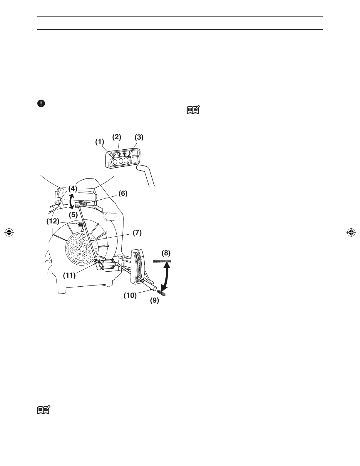
• Check if the adjust lever (outlet valve open/close
lever) is in full close position. Otherwise, large
volumes of chemicals will spout immediately
when the engine starts and are dangerous.
• Assure that there is no person in front of the
spray head (output nozzle) when starting the
engine. Remaining chemicals stuck in the spray
pipe may spout out.
PRECAUTIONS WHEN SPRAYING
• Since protective clothing generally offers
poor ventilation and thus places stress
on the body, there is a risk of contracting
heatstroke or other illness when operating for
long periods under high temperatures. Avoid
spraying on hot days, aiming instead for
early morning and late afternoon times when
temperatures are relatively cool and winds
are low.
• When starting work, pay all due consideration
to the spraying time, wind direction, etc., to
ensure that no noise disturbance or chemical
hazard is caused to nearby residents,
passers-by, farm crops, and so on.
• While spraying hold the grip rmly at all times
and be careful not to point the nozzle in the
direction of people or animals.
• While spraying be careful of the wind
direction and always stand on the upwind
side, to avoid spraying yourself with
chemicals.
• Should you begin to feel even slightly unwell
while spraying, consult a doctor immediately.
When doing so, inform the doctor of the
name of the chemical you were using, the
conditions of use, etc.
• If the sprayer is tilted the chemical may leak
out through the air holes in the cap. When
spraying always make sure you have a rm
footing and maintain your balance.
• Do not touch the spark plugs or plug cords
while the engine is running, as you may get
an electric shock.
• Do not touch the mufer, spark plugs, or
other metal parts with your bare hands while
the engine is running or immediately after
stopping the engine, as there is the risk of
burns due to high temperatures.
PRECAUTIONS AFTER SPRAYING
• Seal unused chemicals and store them out of
the reach of children.
• Do not simply discard empty chemical
containers, but dispose of them safely by
incinerating, burying, or another similar
method. In addition, take every care that the
water used to clean spraying tools does not
create any hazard.
• Fully inspect and maintain protective clothing,
masks, gloves, and other protective gear in
preparation for the next session.
• After completing the work and tidying away
chemicals and spraying tools, you should
immediately take a bath or wash your hands,
feet, face, etc. thoroughly with soap, as well
as washing your mouth out.
• You should change all clothes worn, including
underwear, and wash them thoroughly.
Clothes worn during spraying should not be
worn again the following day.
• After spraying, limit your alcohol intake and
rest thoroughly by going to bed early. If you
feel even slightly unwell, see a doctor as
soon as possible.
OTHER PRECAUTIONS
• When engaged in spraying work over a
protracted period of time, have your health
checked regularly.
• Carry out spraying in a planned fashion,
keeping a daily record of the date and time of
spraying, the chemicals used, the target pest,
contents of the work, duration of the work,
and other details.
• Keep the following points in mind when
selecting or using protective gear.
a) Protective clothing
Choose clothing that is cool to wear and
offers good ventilation and waterproong. In
addition, wear items that enable you to carry
out spraying work in total comfort and safety.
b) Spraying hood
Use a hood with a brim that is waterproof and
covers your neck and shoulders.
H1152413-26,362D28,GB.indd 7 2009-10-15 15.58

8 - English
Safety Precautions
c) Gloves
Use gloves that are difcult for chemicals to
penetrate and do not slip even if you perspire
while doing the work.
d) Rubber apron
When mixing chemicals, wear a long, thick,
and wide apron that cannot be penetrated by
chemical splashes.
e) Protective goggles, mask, etc.
Select suitable protective goggles, mask,
rubber boots, eye washer, and protective
cream, etc., paying attention to standards
and the recommendations of farm work
safety promotion organizations.
MAINTENANCE PRECAUTIONS
• In order to maintain the functions of the
product, regularly carry out the maintenance
inspections listed in this Manual. When
maintenance or parts replacement not
indicated in this Manual are required,
consult your product supplier or nearest
HUSQVARNA product dealer.
• Never keep the engine running while carrying
out inspections or maintenance.
• Do not modify the sprayer or dismantle the
engine. This could lead to breakdown and
serious accidents during operation.
• Do not touch the mufer or spark plugs with
your bare hands immediately after stopping
the engine. There is the risk of burns due to
high temperature.
• For replacement parts, use original
HUSQVARNA parts or brands designated by
HUSQVARNA.
H1152413-26,362D28,GB.indd 8 2009-10-15 15.58

English - 9
Assembly
■ CONNECTION OF EARTH CHAIN
WARNING
Spray of chemicals in dry air may generate
high static electricity due to the friction. To
avoid electric shocks, an earth chain shall be
attached.
(1) Flexible hose
(2) Clamp(Large)
(3) Elbow
(4) Screw
(5) Earth chain
1. Slacken a screw inside of the elbow of the
blower. Insert a part of the earth chain into the
gap between the screw and the main body. Fix
with the screw.
2. Apply a clamp(large) onto the larger end of the
attached flexible hose. Insert a wire of the earth
chain into the hose. Securely fit the hose on the
elbow.
3. Fix the hose securely by tightening the clamp
screw using a screwdriver.
■ CONNECTION OF BLOWER
(1) Flexible hose
(2) Clamp
(3) Wire
(4) Joint
(5) Straight pipe
(6) Bent pipe
1. Connect the blower pipes securely
2. Connect the joint to the flexible hose and fix with
the clamp.
H1152413-26,362D28,GB.indd 9 2009-10-15 15.58

10 - English
Changing discharge rate
362D28 is equipped with an outlet volume
changer mechanism. The volume is initially
set to a “High rate” position in our factory.
Depending on your spray condition, change it to
an adequate position.
IMPORTANT
For Flow dust (FD) powder agents and 1kg-
Weed killers, set to the “Small rate” position.
(1) “Small rate” (2) “Medium rate”
(3) “High rate” (4) Full Open
(5) Full Close (6) Change arm
(7) Rod (8) Full Open
(9) Full Close (10) Adjust lever
(11) Lock Nut (12) Stopper spring
■ HOW TO CHANGE
1. Pull the rod on backrest side of the chemical tank
holder and disengage from the change arm.
2. Insert the upper end of the rod into the required
position hole.
NOTE
In case the rod length does not match with
the hole position, adjust the length in following
manner:
1. Put the adjust lever to “Full open” position
2. Push up the change arm with fingers to “Full
open” position.
3. Slacken the lock nut on the lower end of the rod
and turn the rod till the upper end of the rod
come to “High rate” position. Right turn of the
rod shortens it and left turn makes it longer.
Tighten the lock nut after the adjustment.
NOTE
• Inadequate rod length may cause the rod
disengaged or the shutter improperly operated.
• Even for an operation at “Small rate” or “Medium
rate”, adjustment of the rod length shall be made
to “High rate” position hole. Otherwise, it may
cause an excessive discharge.
Assembly
H1152413-26,362D28,GB.indd 10 2009-10-15 15.58

English - 11
Fuel
■ FUEL
WARNING
• Gasoline is very flammable. Avoid smo king
or bringing any flame or sparks near fuel.
Make sure to stop the engine and allow it
cool before refueling the unit. Select outdoor
bare ground for fueling and move at least 3
m (10 ft) away from the fueling point before
starting the engine.
• The engines are lubricated by oil specially
formulated for air-cooled 2-cycle gasoline
engine use. If Husqvarna oil is not available,
use an anti-oxidant added quality oil expressly
labeled for air-cooled 2-cycle engine use (JASO
FC GRADE OIL or ISO EGC GRADE).
• Do not use BIA or TCW (2-stroke water-cooling
type) mixed oil.
■ RECOMMENDED MIXING RATIO
GASOLINE 50 : OIL 1
• Exhaust emission are controlled by the
funda mental engine parameters and
components (eq., carburation, ignition timing
and port timing) without addition of any
major hardware or the introduction of an
inert material during com bustion.
• These engines are certied to operate on
unleaded gasoline.
• Make sure to use gasoline with a minimum
octane number of 89RON (USA/Canada: 87AL).
• If you use a gasoline of a lower octane
value than prescribed, there is a danger that
the engine temperature may rise and an
engine problem such as piston seizing may
consequently occur.
• Unleaded gasoline is recommended to reduce
the contamination of the air for the sake of your
health and the environment.
• Poor quality gasolines or oils may damage
sealing rings, fuel lines or fuel tank of the
engine.
■ HOW TO MIX FUEL
WARNING
• Pay attention to agitation.
1. Measure out the quantities of gasoline and oil to
be mixed.
2. Put some of the gasoline into a clean, approved
fuel container.
3. Pour in all of the oil and agitate well.
4. Pour in the rest of gasoline and agitate again
for at least one minute. As some oils may be
difcult to agitate depending on oil ingredients,
sufcient agitation is necessary for the engine
to last long. Be careful that, if the agitation is
insufcient, there is an increased danger of early
piston seizing due to abnormally lean mixture.
5. Put a clear indication on the outside of the
container to avoid mixing up with gasoline or
other containers.
6. Indicate the contents on outside of container for
easy identication.
■ FUELING THE UNIT
1. Untwist and remove the fuel cap. Rest the cap
on a dustless place.
2. Put fuel into the fuel tank to 80% of the full
capacity.
3. Fasten the fuel cap securely and wipe up any
fuel spillage around the unit.
WARNING
1. Select bare ground for fueling.
2. Move at least 3 meters (10 feet ) away from
the fueling point before starting the engine.
3. Stop the engine before refueling the unit. At
that time, be sure to sufficiently agitate the
mixed gasoline in the container.
4. Do not smoke or place hot objects near fuel.
■ FOR YOUR ENGINE LIFE, AVOID:
1. FUEL WITH NO OIL (RAW GASOLINE) – It will
cause severe damage to the internal engine
parts very quickly.
2. GASOHOL – It can cause deterioration of rubber
and/or plastic parts and disruption of engine
lubrication.
3. OIL FOR 4-CYCLE ENGINE USE – It can
cause spark plug fouling, exhaust port blocking,
or piston ring sticking.
4. Mixed fuels which have been left unused for
a period of one month or more may clog the
carbu retor and result in the engine failing to
operate properly.
5. In the case of storing the product for a long
period of time, clean the fuel tank after rendering
it empty. Next, activate the engine and empty
the carburetor of the composite fuel.
6. In the case of scrapping the used mixed
oil container, scrap it only at an authorized
repository site.
H1152413-26,362D28,GB.indd 11 2009-10-15 15.58

12 - English
■ STARTING ENGINE
1. Fill the fuel tank with fuel, and turn the cap to the
tank to make sure that it is fixed on tightly.
(1) More than 5mm height space
(2) Fuel tank
IMPORTANT
When refueling the tank, remain more than
5mm height space inside the tank.
2. Push the primer pump several times until over-
flown fuel flows out in the clear tube.
3. Move the choke lever to the closed position.
(1) Choke lever
(2) Primer pump
(3) Close
(4) Open
NOTE
When restarting immediately after stopping the
engine, move the choke lever to the opened
position.
Operation
4. Set the throttle lever to the "START" position.
(1) Full
(2) Start
(3) Idle
(4) Throttle lever
5. To start, hold the top of the duster firmly with your
left hand. Pull the starter knob slowly until you
feel it engage and then give it a vigorous strong
pull.
• Avoid pulling the starter rope out to its full
extension. Do not allow the starter rope to
snap back. Rewind the rope slowly. This will
prevent premature damage to the starter.
6. Once the engine is running, gradually open the
choke if it was set closed, and let the engine run
at idle speed for a minute to warm it up.
NOTE
When the engine failed to start after Several
attempts due to overchoking, open the choke
and repeat pulling the rope.
■ “DECOMP” VALVE
The engine on 362D28 is equipped with a
“Decomp” valve (decompression valve) to
lighten rope tension for starting the engine.
Air leakage noise can be heard by pulling the
rope for starting the engine. This is not an
irregular status; as the engine starts, the valve is
automatically closed and the engine works same
as other engines.
H1152413-26,362D28,GB.indd 12 2009-10-15 15.58

English - 13
■ STOPPING ENGINE
1. Move the regulator lever to the bottom position.
(1) Stop switch
(2) Throttle lever
2. After checking that the powder/granule stops,
move the throttle lever to the idle position.
3. Press the stop switch until the engine stops
completely.
■ CHARGING CHEMICALS (FERTILIZERS/
AGRICHEMICALS)
WARNING
• To charge chemicals into the sprayer tank,
stop the engine and fully down the adjust
lever. In case the adjust lever is in upper
position (the shutter is opened), it is
dangerous as chemicals will be sprayed
simultaneously when the engine starts.
• Tighten the tank cap securely after filling
chemicals. Loose cap may cause danger of
chemicals spout of the tank during use.
IMPORTANT
• Leaving chemicals in the tank for long time may
cause insufficient output volume or incorrect
shutter action due to moisture. Remaining
chemicals shall be separately put into a storage
container within the same day.
• To carry the sprayer by vehicles, empty the
chemical tank. Otherwise, chemicals may be
tamped down by vibration and cause insufficient
output failure.
[Clear button]
After usages, the valve may be locked with
contamination in the engine that makes the rope
heavy.
In such a case, push the Clear button 1 or 2
times with your nger before starting the engine.
The valve will return to a normal position and the
function is recovered.
(1) Clear button
■ IDLE SPEED ADJUSTMENT
In case the engine stalls or runs at too high speed
when the throttle lever is fully down, use the idle
speed adjust screw for readjustment of the idle
speed.
1. Start the engine and set the engine run at middle
speed for a few minute to worm up.
2. Return the throttle to the idle position and adjust
the idle screw.
(1) Idle adjust screw
(2) Rotation increase
(3) Rotation decrease
Operation
H1152413-26,362D28,GB.indd 13 2009-10-15 15.58

14 - English
WARNING
1. Always work from the windward side.
2. Be alert to bystanders or fragile things in the
blowing direction.
1. Put material into the tank with the regulator lever
kept at the bottom position. lf the regulator is
opened, the material will blow out concurrently
with the start of the engine.
(1) Regulator lever
(2) Tank
2. Tighten the tank cap securely.
3. Start the engine and carry the unit on your back.
■ SETTING THROTTLE LEVER
Set the throttle lever to the full throttle position at
the time of spraying work.
(1) Full throttle
(2) Throttle lever
■ SETTING ADJUST LEVER STOPPER)
To maintain shutter opening at the same level for
a spray operation, set the regulator lever stopper
on the required position.
1. Slide the stopper while pulling the knob.
(1) Stopper
(2) Notch
(3) Regulator Lever
2. Release the knob when the stopper is on one
notch above the required opening.
Operation
H1152413-26,362D28,GB.indd 14 2009-10-15 15.58

English - 15
Fig.F13 – F15 show relation between the adjust
lever opening and the Discharge rate for each
type of chemicals.
By referring those Figures based on your applied
chemicals and operation conditions (i.e. spray
area, spray equipment, walking speed, etc.), set
the adjust lever at an adequate position.
■
ADJUSTMENT OF DISCHARGE RATE
IMPORTANT
• Discharge rate can be varied according to grade
and dryness of chemicals
• As granular agents are uneasy to distinguish,
care should be taken not to spray excess
volumes.
• To avoid uneven sprays, try to keep constant
walking speed during the operation.
Operation
H1152413-26,362D28,GB.indd 15 2009-10-15 15.58

16 - English
WARNING
Make sure that the engine has stopped and
is cool before performing any service to the
blower. Contact with rotating blower fan or
hot muffler may result in a personal injury.
■ AIR FILTER
Check the air lter every 25 hours of use or more
frequently if used under dusty conditions. A
clogged air filter may increase fuel consumption
while cutting down the engine power. Never
operate the machine without the air filter or with
a deformed filter element because unfiltered
dusty air may quickly ruin the engine.
CLEANING AIR FILTER:
1. Remove the air lter cover and take out the lter.
Wash it clean in warm, soapy water. Ensure that
the lter is dry before retting it.
2. Use neutral detergent and warm water to clean
the lter element. After cleaning, air dry the
element completely and moisten with a small
amount of 2 cycle motor oil.
■ FUEL FILTER
• A clogged fuel lter may cause poor acceleration
of the engine. Check periodically to see if the
lter is clogged with dirt. The lter can be taken
out of the fueling port using a small wire hook.
Disconnect the lter assembly from the fuel pipe
and unhook the retainer to disassemble it. Clean
the components with gasoline.
■ Spark plug
• After every 50 hours of operation, detach the
spark plug and remove dirt from the electrodes
with a wire brush or similar.
• The correct electrode gap is 0.6 to 0.7mm.
•
When replacing plugs, use designated items.
IMPORTANT
• If too much fuel is absorbed or poor quality oil
is used, the spark plug electrodes become dirty,
making the engine harder to start.
• Note that using any spark plug other than those
designated may result in the engine failing to
operate properly or in the engine becoming
overheated and damaged.
• To install the spark plug, rst turn the plug until it
is nger tight, then tighten it a quarter turn more
with a socket wrench.
■ MUFFLER
WARNING
• Inspect periodically, the muffler for loose
fasteners, any damage or corrosion. If any
sign of exhaust leakage is found, stop
using the machine and have it repaired
immediately.
IMPORTANT
• Before starting operation, always make sure
to check if the mufer is properly held by three
bolts to the cylinder. (Fastening Torque : 8~12
N·m)
PROCEDURES TO BE PERFORMED AFTER
EVERY 100 HOURS OF USE
Maintenance
(1) Screen (2) Element
(3) Holder (4) Retainer
0.6~0.7 mm
H1152413-26,362D28,GB.indd 16 2009-10-15 15.58

English - 17
1. Remove the mufer, insert a screwdriver into the
vent, and wipe away any carbon buildup. Wipe
away any carbon buildup on the mufer exhaust
vent and cylinder exhaust port at the same time.
2. Tighten all screws, bolts, and ttings.
3. Check to see if any oil or grease has worked its
way in between the clutch lining and drum, and
if it has, wipe it away using oil-free, lead-free
gasoline.
■ AIR INLET NET
IMPORTANT
• Blowing air is taken in from the air inlet net.
When air ow has dropped down during
operation, stop the engine and inspect the air
inlet net for blocking by obstacles.
• Note that failure to remove any such obstacles
may result in the engine becoming overheated
and damaged.
WARNING
Never use the blower without the net of the
machine. Before each use, check that the
net is attached in place and is free from any
damage.
■ SHOULDER STRAP
• If the shoulder strap is damaged it may break
during use, thus causing the product to fall
and resulting in personal injury. Follow the
instructions below to replace the shoulder strap
with new one.
1. Pass the upper end of the strap through the
hanger, making the FLAPPED SIDE OUTSIDE.
2. Put the end of the strap through the ring on the
strap, and then push the ring toward the hanger
as close as possible.
Maintenance
(1)Ring
(2)Flapped side
WARNING
The flap on the end of the strap works as
a stopper. Never install the strap with the
flapped side inside, or the unit may fall from
the operation, which could result in injury to
the operator and/or damage to the unit.
■ SPRAY DEVICE
IMPORTANT
• As fertilizers are easy to absorb moisture, left
behind fertilizers will cause error for the
shutter operation. After spraying fertilizers,
clean the spray device carefully.
• Correct length of the chemical tank locking
hooks is 45-46mm. Shorter hooks than this
cause excess fixing forces and may end up
with deformation or breakage of related
components. Longer hooks cause insufficient
contact of the tank and chemicals may leak.
• For long time storage of the sprayer, leave the
chemical tank cap loose. Otherwise, a cap
gasket may be deformed.
(1)Air inlet net
H1152413-26,362D28,GB.indd 17 2009-10-15 15.58

18 - English
WARNING
• When draining fuel, be careful not to spill it. If
fuel is spilt, wipe off thoroughly. In addition,
be sure to close the storage container cap
tightly.
IMPORTANT
• If fuel is left in the engine for protracted periods,
the inside of the carburetor may become
clogged and cause engine malfunction (faulty
starting and insufcient output).
• During storage, slightly loosen the cap of the
chemical uid tank. If screwed too tightly, the
gasket may become distorted.
On completion of all work procedures, when not
planning to use again for a protracted period carry
out the following pre-storage care, to prevent
trouble caused by time-lapse changes.
Storage
Disposal
When disposing your machine, fuel or oil for the
machine, be sure to allow your local regulations.
1. Clean the chemical uid tank and nozzle (see
page 11).
2. Remove dirt from the sprayer, inspect it for any
damage or looseness, and, if any abnormality is
found, correct it thoroughly in preparation for the
next time you use the unit.
3. Drain the fuel tank.
4. Start the engine, and leave it in idling condition
until all the fuel inside the carburetor is spent
and the engine comes to a natural stop.
5. Remove the spark plug and put a few drops (1
to 2 cc) of 2-cycle oil inside the engine. After
pulling the starter rope 2 or 3 times, return the
spark plugs to their original position and stop in
compressed position.
6. After oiling the throttle lever and other metal
parts with anti-corrosive oil, cover the sprayer
and store indoors in a low-humidity location.
Maintenance
(1) Pin (2) Hook
(3) Lever (4) Gasket
(5) Pin (6) Clamp
(7) Shutter case
• When the tank becomes empty, increase the
engine speed, and up and down the adjust lever
several times to blow away adhered chemicals
from the shutter, inside of the blower, spray head,
etc.
• Periodically detach the chemical tank and
remove chemicals adhered to the shutter case.
How to Detach the Chemical Tank
1. Disengage the adjust rod from the change arm.
2. Push up tank fixing levers on both sides of the
blower top, and remove hooks.
H1152413-26,362D28,GB.indd 18 2009-10-15 15.58

English - 19
The solution ow is changed by shifting the
number on the top of the valve at the mist
nozzle. The gure shows 4 lit/min. position.
The spray range is changed by shifting the bell
position after loosening the lock ring.
(A) Pulled out position: Long distance, narrow angle
spray
(B) Pushed In position: Short distance, wide angle
spray
3. Start the engine and carry the unit on your back.
4. While holding the swivel joint in your right hand,
move the throttle lever upward and turn the
intermediate valve to the open position.
5. After spraying work has nished, close the
intermediate valve and stop the engine.
WARNING
• Before the solution spraying work, supply
water into the tank and operate the mister to
make sure that there is any leakage or any
mechanical failure.
• Repair it if there is any leakage or failure
before the solution spraying work.
Discharge rate
Valve travel (lit/min.)
1 1
2 2
3 3
4 4
Max. Longitudinal coverage
Horizontal direction : 12 m
Vertical direction : 12 m
■ COMPONENTS
(A) Tank
(B) Intermediate valve
(C) Mist nozzle
■ ASSEMBLY
Connect the blow pipes and route the solution tube
from the material tank to the mist nozzle.
(1) Clamp A (6) Bent pipe
(2) Flexible hose (7) Mist nozzle
(3) Clamp B (8) Intermediate valve (xed
with Clamp B)
(4) Solution tube (9) Clip
(5) Swivel joint (10) Clamp C
■HOW TO USE
1. Pour the solution into the tank with the
intermediate valve closed.
2. Adjust the solution ow and the spray range
according to work conditions.
Mist kit (Available as accessory)
H1152413-26,362D28,GB.indd 19 2009-10-15 15.58

H1152413-26,362D28,GB.indd 20 2009-10-15 15.58
Table of contents
Other Husqvarna Paint Sprayer manuals

Husqvarna
Husqvarna HDE4P Owner's manual

Husqvarna
Husqvarna HS2 Owner's manual

Husqvarna
Husqvarna 325S25 User manual

Husqvarna
Husqvarna HS2 Owner's manual

Husqvarna
Husqvarna BP4P User manual

Husqvarna
Husqvarna BP5 Owner's manual

Husqvarna
Husqvarna 323S15 User manual

Husqvarna
Husqvarna HDE4E Owner's manual

Husqvarna
Husqvarna BP4E Owner's manual

Husqvarna
Husqvarna 321SP User manual
Popular Paint Sprayer manuals by other brands

Mesto
Mesto 3275M Instructions for use

OHAUS
OHAUS SHLD0415AL instruction manual

Cima
Cima PLUS Operation and maintenance instructions

WALTHER PILOT
WALTHER PILOT wa200 operating instructions

Thermo Scientific
Thermo Scientific MaxQ 2000 CO2 Plus user manual

Carlisle
Carlisle Ransburg RansFlex RFXi Series Service manual