Binks Signature Series User manual

Binks Model 95
SPRAY GUN
6121-XXXX-X
Mo el 95 Signature Series
Spray Gun
This handheld gun is the premier spray
gun in the Binks line. A combination
of the three best industrial spray guns,
odel 95 sets a new standard.
The odel 95 is a high production
gun with stainless steel fluid passages
which may be used with most coat-
ings. This new gun replaces odels
18, 62 and BBR spray guns, incorpo-
rating the best features of all three:
drop-forged anodized alumninum
body, stainless steel fluid passages,
adjustable floating needle valve, stain-
less steel or tungsten carbide fluid
nozzle, plated drop-forged brass self-
centering air nozzle, brass air valve
cartridge, adjustable spray pattern,
3/8" NPS(m) fluid inlet, 1/4" NPS(m)
air inlet. Weight 1 lb., 11 oz.
Illustration Key
1. Air Nozzle Assembly
2. Gun Body
3. Side Port Controls
4. Fluid Control Knob
5. Air Connection 1/4" NPS(m)
6. Fluid Connection 3/8" NPS(m)
1
3
2
4
5
6
Replaces
Part Sheet
77-2625R-8
Part
Sheet
77-2625R-9
PRESSURE FEED TANK HOOKUP
For medium production spraying (sin -
gle regulator).
Air pressure for atomi zation is regulated
at extractor, fluid pressure at tank regulator
(see figure 3).
PRESSURE FEED TANK HOOKUP
For portable painting operations
(double regulator).
Air pressure for atomization and fluid
supply is regulated by two individual air
regulators on tank (see figure 4).
TYPES OF INSTALLATION
SIPHON FEED CUP HOOKUP
Air pressure for atomization is regulated at
extractor. The amount of fluid is adjusted by
fluid control screw on gun, viscosity of paint,
and air pressure (see figure 1).
PRESSURE FEED CUP HOOKUP
For fine finishing with limited spraying.
Air pressure for atomization is regulated at
extractor; fluid pressure at cup regulator. For
heavy fluids and internal mix nozzle spray-
ing, fluid adjusted by control screw on gun.
Pressure cup also available less regulator
(see figure 2).
Extractor
Figure 1
Air
Siphon Cup
Extractor
Figure 5
Air
Flui
Flui
Regulator
Flui
Figure 4
Air
Supply
Air Supply
Extractor
Air
Inlet
Figure 3
Air
Flui
Outlet
Pressure
Tank
Pressure
Tank
Flui
Oil & Water
Extractor
Cup
Regulator
Figure 2
Air
Flui
Pressure Cup
PRESSURE FEED CIRCULATING
HOOKUP
For heavy production spraying.
Air pressure atomization regulated at
extractor. Fluid pressure regulated at fluid
regulator (see figure 5).

2
WARNING
!
In this part sheet, the words WARNING, CAUTION and NOTE are used to emphasize important safety information as follows:
CAUTION
Hazar s or unsafe practices which coul
result in minor personal injury, pro uct
or property amage.
!
WARNING
Hazar s or unsafe practices which coul
result in severe personal injury, eath or
substantial property amage.
!
NOTE
Important installation, operation or
maintenance information.
Rea the following warnings before using this equipment.
READ THE MANUAL
Before operating finishing equipment read and
understand all safety operation and maintenance
information provided in the operation manual.
AUTOMATIC EQUIPMENT
Automatic equipment may start suddenly without
warning.
INSPECT THE EQUIPMENT DAILY
Inspect the equipment for worn or broken parts
on a daily basis. Do not operate the equipment
if you are uncertain about its condition.
NEVER MODIFY THE EQUIPMENT
Do not modify the equipment unless the
manufacturer provides written approval.
KNOW WHERE AND HOW TO SHUT OFF THE
EQUIPMENT IN CASE OF AN EMERGENCY
PRESSURE RELIEF PROCEDURE
Always follow the pressure relief procedure in the
equipment instruction manual.
NOISE HAZARD
You may be injured by loud noise. Hearing
protection may be required when using this
equipment.
STATIC CHARGE
Fluid may develop a static charge that must be
dissipated through proper grounding of the
equipment objects to be sprayed and all other
electrically conductive objects in the dispensing
area. Improper grounding or sparks can cause a
hazardous condition and result in fire explosion
or electric shock and other serious injury.
FIRE AND EXPLOSION HAZARD
Never use 1 1 1-trichloroethane methylene
chloride other halogenated hydrocarbon solvents
or fluids containing such solvents in equipment
with aluminum wetted parts. Such use could
result in a serious chemical reaction with the
possibility of explosion. Consult your fluid
suppliers to ensure that the fluids being used are
compatible with aluminum parts.
WEAR SAFETY GLASSES
Failure to wear safety glasses with side shields
could result in serious eye injury or blindness.
OPERATOR TRAINING
All personnel must be trained before operating
finishing equipment.
EQUIPMENT MISUSE HAZARD
Equipment misuse can cause the equip ment to
rupture malfunction or start unexpectedly and
result in serious injury.
KEEP EQUIPMENT GUARDS IN PLACE
Do not operate the equipment if the safety
devices have been removed.
PROJECTILE HAZARD
You may be injured by venting liquids or gases
that are released under pressure or flying debris.
PINCH POINT HAZARD
Moving parts can crush and cut. Pinch points are
basically any areas where there are moving parts.
DE-ENERGIZE, DEPRESSURIZE, DISCONNECT
AND LOCK OUT ALL POWER SOURCES DURING
MAINTENANCE
Failure to De-energize disconnect and lock out
all power supplies before performing equipment
maintenance could cause serious injury or death.
TOXIC FLUID & FUMES
Hazardous fluid or toxic fumes can cause serious
injury or death if splashed in the eyes or on the skin
inhaled injected or swallowed. LEARN and KNOW
the specific hazards of the fluids you are using.
WEAR RESPIRATOR
Toxic fumes can cause serious injury or death if
inhaled. Wear a respirator as recommended by
the fluid and solvent manufacturer’s Material
Safety Data Sheet.
PROP 65 WARNING
WARNING: This product contains chemicals known
to the State of California to cause cancer and
birth defects or other reproductive harm.
CA PROP
65
IT IS THE RESPONSIBILITY OF THE EMPLOYER TO PROVIDE THIS INFORMATION TO
THE OPERATOR OF THE EQUIPMENT.
FOR FURTHER SAFETY INFORMATION REGARDING BINKS AND DEVILBISS EQUIPMENT,
SEE THE GENERAL EQUIPMENT SAFETY BOOKLET (77-5300).

3
The first requirement for a good resultant finish is
the proper handling of the gun. The gun should be
held perpendicular to the surface being covered and
moved parallel with it. The stroke should be started
before the trigger is pulled and the trigger should
be released before the stroke is ended. This gives
accurate control of the gun and material.
The distance between gun and surface should be 6
to 12 inches depending on material and atomizing
pressure. The material deposited should always be
even and wet. Lap each stroke over the preceding
stroke to obtain a uniform finish.
NOTE
To re uce overspray an obtain maximum efficiency, always
spray with the lowest possible atomizing air pressure.
Coating shoul be even
an wet when spraying
Coating will
be light at
this point
Coating will
be heavy
at this point
Start
stroke
Pull
trigger
Release
trigger
En of
stroke
RIGHT
WRONG
TRAVEL OF GUN
6 to 12 inches
AIR PRESSURE
GUN HANDLING
BINKS OIL AND WATER EXTRACTOR IS IMPORTANT
5/16” 1/4”
Only 34 PSI at gun inlet
25 feet of 1/4” I.D. ho e cau e a drop of
26 PSI between the air upply and the gun.
(NOT RECOMMENDED)
48 PSI at gun inlet
25 feet of 5/16” I.D. ho e cau e a drop of
12 PSI between the air upply and the gun.
For thi rea on Bink recommend the u e
of 5/16” ho e.
(RECOMMENDED)
With 60 psi applie at air supply
Atomizing pressure must be set properly to allow for the drop
in air pressure between the regulator and the spray gun.
Achieving a fine spray finish without the use of a
good oil and water extractor is virtually impossible.
A Binks regulator / extractor serves a double pur-
pose. It eliminates blistering and spotting by keep-
ing air free of oil and water, and it gives precise air
pressure control at the gun.
Binks recommends using odel HFRL-508 Oil and
Water Extractor / Regulator. See your local distributor
for other models.
Cro ection view
howing compari on of in ide
ho e diameter (actual ize).
60 lb . regulated pre ure
It is extremely poor practice to mount the oil and
water extractor on or even near the compressor unit.
The temperature of the air is greatly increased as it
passes through the compressor and this compressed
air must be cooled before the moisture in it will con-
dense. If the air from the compressor is still warm
when it passes through the oil and water extractor,
moisture will not be effectively removed, but will
remain in suspension. Then, when the air cools in
the hose beyond the extractor, the moisture will
condense into drops of water and cause trouble.
Air lines must be properly raine
Pitch all air lines back towards the compressor so
that condensed moisture will flow back into the air
receiver where it can be removed by opening a
drain. Every low point on an air line acts as a water
trap. Such points should be fitted with an easily
accessible drain. See diagram.
AIR SUPPLY

4
In normal operation the wings on
the nozzle are horizontal as illus-
trated here. This provides
a vertical fan shaped pattern which
gives maxi-
mum coverage
as the gun is
moved back
and forth par-
allel to the
surface being
finished.
Spray width adjustment: Turn clock-
wise for round, counterclockwise for fan.
Fluid control screw: Turn clockwise to
decrease flow, counterclockwise to
increase flow.
As width of spray is increased, more
material must be allowed to pass through
the gun to obtain the same coverage on
the increased area.
SIPHON SPRAYING
Set atomization pressure at approximate-
ly 50 PSI for lacquer and 60 PSI for
enamel. Test spray. If the spray is too
fine, reduce the air pressure or open fluid
control screw. If the spray is too coarse,
close the fluid control screw. Adjust the
pattern width and repeat adjustment of
spray if necessary.
PRESSURE SPRAYING
After selecting correct size fluid orifice,
set fluid pressure for desired flow. Open
atomization air and test spray. If spray is
too fine, reduce air pressure. If spray is
too coarse, raise air pressure. Adjust pat-
tern width and repeat adjustment of spray.
Keeping fluid control screw in open posi-
tion will reduce fluid needle wear.
The spray pattern of
the Binks gun is variable
from round to flat with
all patterns in between.
Spray width
adjustment
Fluid
control
screw
FAULTY PATTERNS AND HOW TO CORRECT THEM
PATTERN CAUSE CORRECTION
Dried material around the
outside of the fluid nozzle tip
at position “C” restricts the
passage of atomizing air at
one point through the center
opening of air nozzle and
results in pattern shown.
This pattern can also be caused
by a loose air nozzle.
Dried material in side-port
“A” restricts passage of air.
Greater flow of air from
cleaner side-port “B” forces
fan pattern in direction of
clogged side.
Dissolve material in side-ports with thinner
then blow gun clean. Do not poke into
openings with metal instruments.
Remove air nozzle and wipe off fluid tip
using rag wet with thinner. Tighten air
nozzle.
A split spray or one that is heavy on each
end of a fan pattern and weak in the mid-
dle is usually caused by:
(1) Too high an atomization air pressure
(2) Attempting to get too wide a spray pat-
tern with thin material.
Reducing air pressure will correct cause (1).
To correct cause (2) open material control
to full position by turning to left. At the
same time turn spray width adjustment to
right. This will reduce width of spray but
will correct split spray pattern.
(1) Dried out packing around material nee-
dle valve permits air to get into fluid
passageway. This results in spitting.
(2) Dirt between fluid nozzle seat and
body or loosely installed fluid nozzle
will make gun spit.
(3) A loose or defective swivel nut on
siphon cup or material hose can cause
spitting.
To correct cause (1) back
up knurled nut (E) place
two drops of machine oil
on packing replace nut
and tighten with fingers
only. In aggravated cases
replace packing.
To correct cause (2) remove fluid nozzle (F)
clean back of nozzle and nozzle seat in gun
body using rag wet with thinner replace
nozzle and draw up tightly against body.
To correct cause (3) tighten or replace
swivel nut.
E
FG

5
SPRAY GUN CLEANING INSTRUCTIONS
MAINTENANCE
In certain states it is now against the law
to spray solvents containing Volatile
Organic Compounds (VOC)’s into the
atmosphere when cleaning a spray gun. In
order to comply with these air quality
laws Binks recommends one of the fol-
lowing two methods to clean your spray
finishing equipment:
1. Spray solvent through the gun into a
closed system. An enclosed unit or
spray gun cleaning station condenses
solvent vapors back into liquid form
which prevents escape of VOC’s into
the atmosphere.
2. Place spray gun in a washer type
cleaner. This system must totally
enclose the spray gun, cups, nozzles
and other parts during washing, rins-
ing and draining cycles. This type of
unit must be able to flush solvent
through the gun without releasing any
VOC vapors into the atmosphere.
Additionally, open containers for storage
or disposal of solvent or solvent-contain-
ing cloth or paper used for surface prepa-
ration and clean-up may not be used.
Containers shall be nonabsorbent.
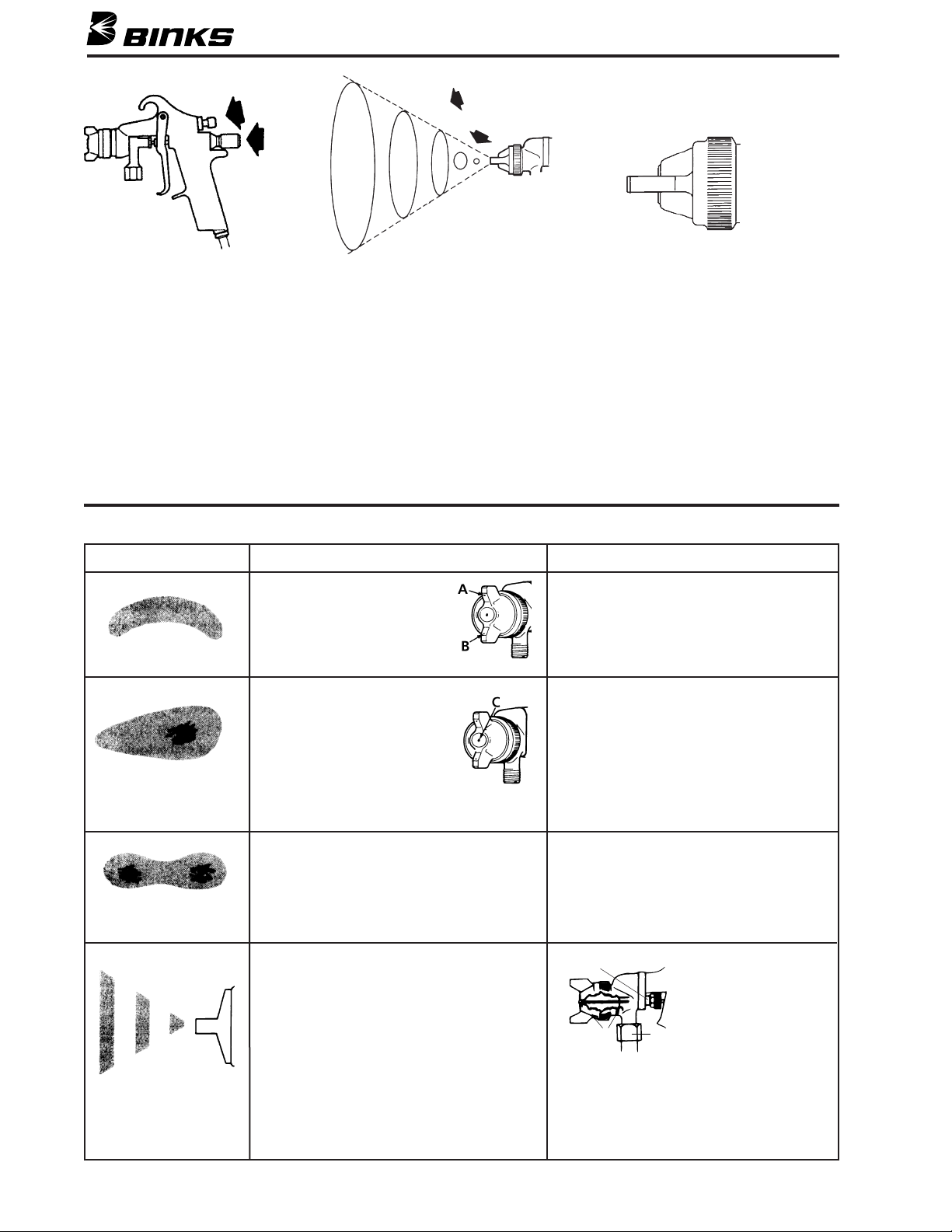
AIR AND FLUID NOZZLE
CLEANING
A faulty spray pattern is often caused by
improper cleaning resulting in dried
materials around the material nozzle tip
or in the air nozzle. Soak these parts in
thinners to soften the dried material and
remove with a brush or cloth.
If either the air nozzle or fluid nozzle are
damaged, these parts must be replaced
before perfect spray can be obtained.
CLEANING GUN USED WITH
1 QUART CUP
Relieve pressure in the cup. Then,
unscrew, empty and carefully rinse cup
out with thinners. Place clean thinners in
the cup and spray this through the gun
until it is clean. Blow air through gun to
dry it.
CLEANING GUN USED WITH
PRESSURE CONTAINER
Hold a piece of cloth wadded in the hand
over the gun nozzle and pull the trigger.
The air will back up through the material
nozzle and force the material out of the
hose into the container. Empty container.
Put enough thinners into the container to
wash the hose and gun thoroughly and
spray this through the gun until it is clean.
Then blow out the material hose to dry it
and remove all traces of material by
attaching it to the air line.
CLEANING GUN USED WITH
PAINT CIRCULATING SYSTEM
Shut off material supply and remove
material hose from gun. Clean gun as
used with siphon cup or pressure contain-
er or connect quick release on paint line
solvent line. To ensure clean air to spray
gun, use Binks oil and water extractor.
See your Binks distributor for the correct
model.
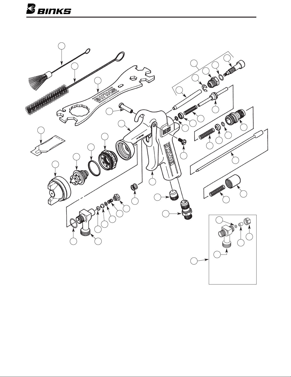
TO REPLACE AIR VALVE AND
SPINDLE ASSEMBLY
Remove material valve control knob (21),
spring (18), and needle assembly (20).
Unscrew housing (19), and remove spin-
dle assembly (17) with springs (16 & 18),
housings (15), and o-rings (14). Lubricate
new o-rings with Gunners ate.
Assemble components using material
needle. Place this assembly along with
housing (19) into gun body and screw
into position. Remove material needle
(20) and tighten housing (19).
TO REPLACE NEEDLE SEAL
AND GLAND ADAPTER IN
FLUID INLET
Remove material valve control knob (21)
and spring (18) and pull out fluid
needle (20). Unscrew packing nut (30)
and remove spring (29) and seal backup
(28). Using a no. 10 x 1-1/4" coarse-
thread wood screw (Binks Part No. 20-
6536) or small sheet metal screw, remove
the needle seal (27) and gland adapter
(26). Replace gland adapter (26) and nee-
dle seal (27). Re-insert seal backup (28)
spring (29) and screw on packing nut (30)
a couple of turns so it fits loosely by
hand. Reassemble fluid needle (20),
spring (18) and material valve control
knob (21). Finally, tighten packing
nut (30) until it bottoms out on fluid
inlet (25).
LUBRICATION
Lubricate daily, all moving parts includ-
ing trigger pivot point and air valve spin-
dle and with Binks Gunners ate (44).
WARNING
Injection of material from the gun
into the skin may result in serious
personal injury. Shut off the air
supply to the container an release
the pressure on the container before
attempting to clean the gun.
!
CAUTION
Never use metal instruments to
clean the air or material nozzles.
These parts are carefully machine
an any amage to them will cause
faulty spray.
!

6
43
46
42
44
1
2
3
4
5
6
7
14
15
16
17
18
15
14
19
20
21
18
9
10
11
12
13
8
24
23
22
31
30
29
28
27
26
2545
Binks Mo el 95 SPRAY GUN
47
48
49
50
Optional for vitreous
applications,
or er Flui Inlet
Assembly Kit 54-4511.
51

ITEM PART
NO. NO. DESCRIPTION QTY.
1* AIR CAP ASSEMBLY .............................. 1
2* FLUID NOZZLE (Stainless Only) ............... 1
3 54-918•^ SEALING RING ....................................... 1
4 54-4215 HEAD INSERT......................................... 1
5— 95 SERIES GUN HANDLE....................... 1
6 54-3580 TRIGGER STUD ...................................... 1
7 54-3581 TRIGGER SCREW ................................... 1
8 54-4216 SIDE PORT CONTROL ASSEMBLY ......... 1
9 54-4219 CONTROL STEM .................................... –
10 54-3511RETAINING RING ................................... –
11 54-4218 CONTROL BODY ................................... –
12 20-6160 O-RING................................................... –
13 54-4217 CONTROL SCREW.................................. –
14 20-4615^ O-RING................................................... 2
15 54-3515 HOUSING ............................................... 2
16 54-3520 SPRING (Yellow)...................................... 1
17 54-3512SPINDLE ASSEMBLY .............................. 1
18 54-3518 SPRING (Blue – 6 lbs. 8 oz.) ..................... 2
19 54-3541 HOUSING ............................................... 1
20 * FLUID NEEDLE (Stainless Only)................ 1
21 54-3606 MATERIAL VALVE CONTROL KNOB ..... 1
22 54-768 AIR CONNECTION ................................. 1
ITEM PART
NO. NO. DESCRIPTION QTY.
23 54-3504 PLUG...................................................... 1
24 54-3578 TRIGGER ................................................ 1
25 54-4210 FLUID INLET........................................... 1
26 54-4264•GLAND ADAPTER.................................. –
27 54-4265•NEEDLE SEAL......................................... –
28 54-4266•SEAL BACKUP........................................ –
29 54-4267•SPRING................................................... –
30 54-4263•PACKING NUT ....................................... –
31 54-3513 VALVE SPINDLE CAP ............................. 1
43 82-469 GUN BRUSH........................................... 1
44 — GUNNERS MATE (3cc) ............................ 1
45 54-3592•COPPER GASKET ................................... 1
OPTIONAL ACCESSORIES (Please or er separately)
42 54-4213 WRENCH (Optional)................................ 1
46 OMX-88 GUN BRUSH (Optional)........................... 1
— 6-429 GUNNERS MATE (20 ea. 2 oz. bottles) ..... 1
OPTIONAL SPRINGS (Please or er separately)
18 54-4427 HEAVY DUTY SPRING (29 lbs.)............... 1
PARTS LIST
(When ordering please specify Part No.)
FOR VITREOUS APPLICATIONS – PLEASE ORDER SEPARATELY
SEE PAGE 8 FOR OPTIONAL NOZZLE SETUPS
ITEM PART
NO. NO. DESCRIPTION QTY.
49 54-4531▲•PACKING SPACER.................................. 1
50 54-4542▲NUT ASSEMBLY ..................................... 1
51 54-4511▲FLUID INLET ASSEMBLY (VITREOUS).... 1
* See Air Cap Fluid Nozzle and Needle Selection Chart page 8.
Part of Repair Kit 54-3577 (Fluid Inlet and Air Valve Kit). Available only as a part of its assembly.
•Part of Repair Kit 54-4225 (Fluid Inlet Packing Kit).
Part of Repair Kit 54-4226 (Air Valve Spindle Kit).
^ Part available separately in package of 5 (add -5 to part number).
ITEM PART
NO. NO. DESCRIPTION QTY.
47 54-4568▲FLUID INLET........................................... 1
48 20-2227▲•O-RING................................................... 1
▲Part of Fluid Inlet Assembly Kit 54-4511 (optional for vitreous applications). •Part of Repair Kit 54-4225 (Fluid Inlet Packing Kit).
Part of Repair Kit 54-3577 (Fluid Inlet and Air Valve Kit). Available only as a part of its assembly.

8
Nozzle No. 59ASS 59BSS 59CSS 63SS 63ASS 63BSS 63CSS 65SS 66SS 67SS 68SS
Orifice Size .171 .218 .281 .028 .040 .046 .052 .059 .070 .086 .110
NOZZLE an NEEDLE SELECTION CHARTS
VERY THIN 63ss x 63P PE 4.5 7.5 10.0 5 663
14-16 secs. Zahn 2 Cup 63Bss x 63PB PE 9.0 14.3 20.0 14 663A
Wash primers dyes 66ss x 66SD SE 7.9 12.1 — 10.5 665
stains solvents 66ss x 66SK SE 11.0 15.2 19.5 13 665
water inks 63Bss x 200 PI 3.1 5.2 6.4 12 663A
THIN 63Ass x 63P PE 5.1 8.37 12.2 11 663A
16-20 secs. Zahn 2 Cup 63Bss x 63PE PE 9.5 15.0 20.0 13 663A
Sealer lacquers primers 66ss x 66SK SE 11.0 15.2 19.5 13 665
inks lubricants 63Bss x 200 PI 3.1 5.2 6.4 12 663A
zinc chromates acrylics
MEDIUM 63Bss x 63PB PE 9.0 14.3 20.0 14 663A
19-30 secs. Zahn 2 Cup 63Css x 63PE PE 9.5 15.0 20.0 13 663A
Synthetic enamels varnishes 66ss x 66SD SE 7.9 12.1 — 11 665
shellacs fillers primers 66ss x 66SK SE 11.0 15.2 19.5 13 665
epoxies urethanes lubricants
63Css x 200 PI 3.1 5.2 6.4 12 663A
wax emulsions enamels
HEAVY 67ss x 67PB PE 9.5 14.9 19.5 12 667
(Cream-like) 68ss x 68PB PE 9.5 14.1 19.1 12 668
Over 28 secs. No. 4 Ford Cup 67ss x 206 PI 6.0 9.5 13.0 15 667
VERY HEAVY 68ss x 68PB PE 9.5 14.1 19.1 12 668
Texture coatings 68ss x 206 PI 6.2 9.8 13.2 15 668
Road marking paint 59Ass x 244 PI 7.8 11.5 15.2 12 659
59Ass x 245 PI 7.8 11.5 15.2 6 659
59Bss x 251 PI 7.8 11.5 15.2 12 659
59Bss x 252 PI 7.8 11.5 15.2 6 659
59Css x 262 PI 7.3 11.0 14.7 6 659
68ss x 206 PI 6.2 9.8 13.2 15 668
ADHESIVES 63Bss x 66SD-3 PE 7.9 12.1 16.2 4 663
Waterbase white vinyl glues 67ss x 67PB PE 9.5 14.1 19.1 12 667
Solvent base neoprenes 66ss x 66SD-3 PE 7.9 12.1 16.2 10 665
(contact cement) 66ss x 66SDJG PE 10.4 ——8-9 665
66ss x 66R PE/SE — 4.2 — RD 665
L6SS x 66SD-3 PE 9.5 14.2 19.0 10 665
L3BSS x 66SD-3 PE 9.5 14.2 19.0 10 663A
CERAMICS 67VT x 67PD PE 10.0 15.0 20.0 15 667VT
Similar abrasive materials 68VT x 68PB PE 9.5 14.1 19.1 12 668VT
glazes engobes
porcelain enamel
BUFFING COMPOUNDS 64VT x 64PA PE 12.1 15.0 21.0 13 664VT
67VT x 67PD PE 10.0 15.0 20.0 15 667VT
CONCRETE CURING 66ss x 200 PI 3.1 5.2 6.4 15 665
COMPOUNDS 67ss x 206 PI 6.0 9.5 13.0 18 667
68ss x 206 PI 6.2 9.8 13.2 20 668
MULTICOLOR PAINTS 66ss x 200 PI 3.1 5.2 — 12 665
67ss x 206 PI 6.0 9.5 — 15 667
66ss x R3 PI — 4.2 — FAN 665
66ss x R8 PI — 4.2 — FAN 665
TEFLONS 63Ass x 63PB PE 9.0 14.3 20.1 10 663A
66ss x 66SD PE 7.9 12.1 —7 665
HAMMERS 63ss X 63PB PE 9.0 14.3 — 14 663A
66ss X 63PB PE 9.0 14.3 — 14 665
66ss X 66SD PE 7.9 12.1 —7 665
WRINKLE ENAMELS 63Css x 63PB PE 9.0 14.3 20.0 10 663A
66ss x 63PB PE 9.0 14.3 20.0 10 665
ZINC RICH COATINGS 66ss x 67PD PE 12.0 18.0 24.0 15 665N
67VT x 67PB PE 9.5 14.1 19.1 12 667VT
Note: PE - Pressure External SP - Siphon External PI - Pressure Internal
TYPE OF FLUID FLUID NOZZLE CFM AT MAX FLUID NEEDLE NOS.
TO BE SPRAYED X AIR TYPE 30 50 70 PATTERN FOR SPRAY GUN
NOZZLES PSI PSI PSI AT 8" MODEL 95

SPECIAL NOZZLES – INTERNAL MIX HEAVY MATERIAL
SEE CHART AIR & FLUID NOZLES
SPECIAL NOZZLE – CLEANING
FLUID
NOZZLE
AIR NOZZLE
#54-2065
RING
#54-1583
BASE
#659 NEEDLE
ASSEMBLY
GUIDE
#54-1584 RING
(USED WITH 200 SERIES
TIPS ONLY
NOZZLE TIP:
200 SERIES,
NITRALLOY
SCREW
#54-928 10" CLEANING ATTACHMENT
(REQUIRED FOR DEGREASING AND LUBRICATING
9

10

11

U.S.A./Canada Customer Service
ITW Finishing Equipment Americas
195 Internationale Blvd.
Glendale Heights, IL 60139
630-237-5000
Toll Free Customer Service
and Technical Support
800-992-4657
Toll Free Fax
888-246-5732
Binks Sales and Service: www.binks.com
WARRANTY
This product is covered by Binks’ 1 Year Limited Warranty.
3/11 ©2011 ITW Finishing Equipment Americas All rights reserved. Printed in U.S.A.
77-2625R-9 Revisions: (P7) Updated Parts List;
(P9) Deleted Multi-color Conversion Kit;
(P12) Updated contact information.
This manual suits for next models
1
Table of contents
Other Binks Paint Sprayer manuals

Binks
Binks TROPHY SERIES User manual

Binks
Binks AA4000 User manual

Binks
Binks HP 6/60 User manual

Binks
Binks Mag II User manual

Binks
Binks Mach 1A HVLP User manual

Binks
Binks AA4400A User manual

Binks
Binks 44-6000 Troubleshooting guide

Binks
Binks 202-755 User manual

Binks
Binks AA4400M User manual

Binks
Binks 230 User manual

Binks
Binks 400-HF0000 HVLP AA10 AIR CAP User manual

Binks
Binks 550 User manual

Binks
Binks 460 User manual

Binks
Binks 2100 SERIES User manual

Binks
Binks HP 4/32 User manual

Binks
Binks 7N User manual

Binks
Binks MACH 1AR HVLP User manual

Binks
Binks TROPHY AA 4400 User manual

Binks
Binks 2001 User manual

Binks
Binks 2100 SERIES User manual