Casotti AQUILOTTO FC8-2 Guide

2 SIDES
code FC8-2
Version 2/2018
Instruction for the installation and the adjustment
CASOTTI DEVICE TO INTERRUPT FLUID SPILLS BETWEEN TREES
Made in Italy since 1966
Quello che mancava

2 3
AQUILOTTO 2 SIDES is an electronic device designed and
engineered to cut the liquid flow in-between two subsequent trees.
It can be mounted very easily to any type of sprayers: air blast
sprayers, equipments with DUPIGET OLIVO or 2 ELECTROGET
OLIVO.
AQUILOTTO 2 SIDES consists of 3 parts:
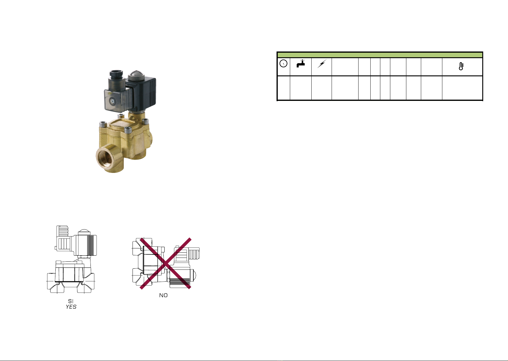
Control unit with double timer and 2 optical readers with solenoid
valve.
The function of the optical reader is to find the presence of the
trunk or leaves and give the impulse for the fluid opening.
The Control unit allows accurately controlling all functions of
AQUILOTTO 2 SIDES.
WHAT IS AQUILOTTO 2 SIDES
• Electronic control unit
• 2 optical readers with solenoid valve and installation bracket
• Electrical connection cables
• Hydraulic pipes and connections
• Frame to install the optical reader
WHAT IS INCLUDED
WHAT IS NOT INCLUDED
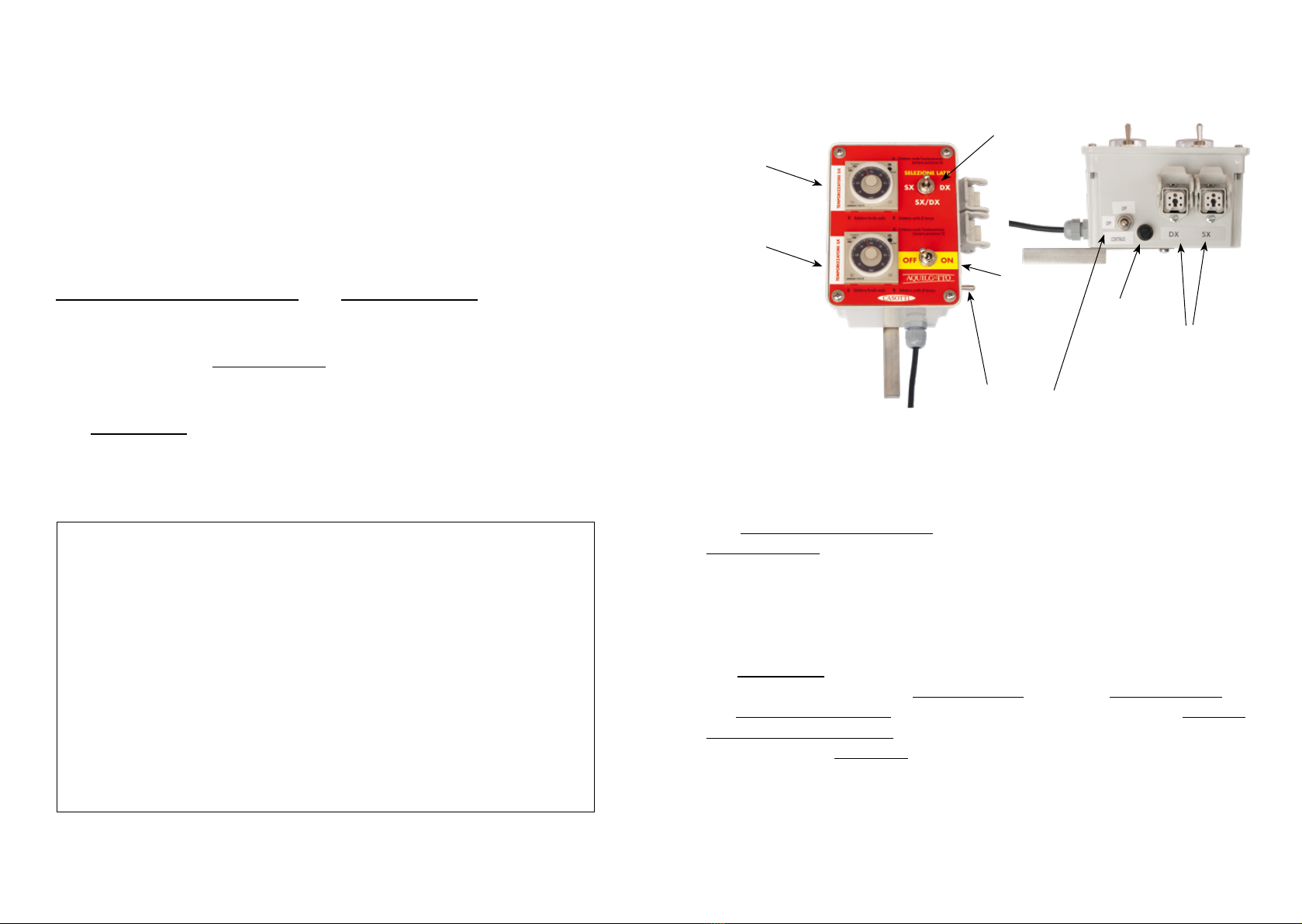
Continuous
operation switch
Working
side selector
Fuse
Main
switch
ON/OFF
5-pole sockets
to connect
the OPTICAL
READERS
Right timer
Left timer
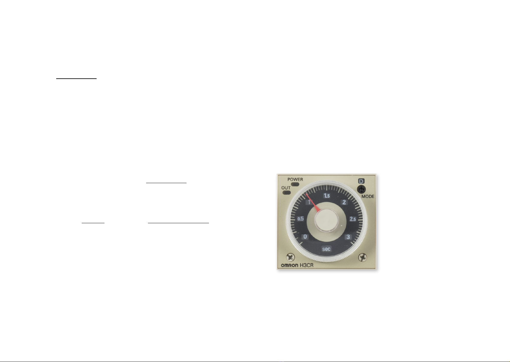
The control unit with 2 timers is used to adjust the closing time of the
solenoid valves (energisation delay), allowing the fluid to be discharged
accurately.
A magnet is installed on the back of the control unit, in order to place it
comfortably in the cab.
AQUILOTTO 2 SIDES is supplied power by connecting the control unit
plug to the 12V power outlet of the tractor.
The main switch turns the entire device on and off; in OFF position, it also
cut off power supply to the optical readers and to the solenoid valves.
The continuous operation switch in ON position is used to keep the solenoid
valve of the selected side always open, effectively bypassing the impulse
coming from the Photocells and discharging the fluid continuously.
CONTROL UNIT WITH 2 TIMERS

4 5
EXAMPLES OF FRAME FOR THE APPLICATION
OF THE OPTICAL READER
The frame shall be constructed considering dimensions of Aquilotto
to avoid projection from the outline of the tank
AQUILOTTO movement axis
1
150 cm about
frame to be applied
to the tank
AQUILOTTO movement axis
2
150 cm about
frame to be applied
to the tank
The function of the optical reader is to find the presence of the trunk or
leaves and give the impulse for the fluid opening.
The optical reader must be positioned approximately one meter before
the sprayer nozzles or the oscillating nozzles.
It must be installed so that its distance from the nozzles can be changed
in order to open the fluid discharge earlier when needed.
The maximum reading distance of the photocell is 400 cm.
The maximum reading can change according to the weather and the
position of the sun.
The metal case containing the photocell has two functions: to prevent the
interference of solar rays as much as possible and to protect the optical
reader from accidental impacts.
The photocell works at night as well.
OPTICAL READER WITH SOLENOID VALVE
Solenoid valve
Photocell protected
by a metal case
Cable with 5-pole plug
to connect the OPTICAL
READER to the control
unit

6 7
HOW TO ADJUST AQUILOTTO
AQUILOTTO 2 SIDES requires some simple adjustments for proper
operation.
1)
Position the optical reader at approx. one meter from the nozzles in order
to discharge fluid approx. 10/15cm before the leaves.
The photocell reading system is like an invisible ray which is perfectly
straight in front of the photocell.
This ray can be oriented by moving the case, performing a reading earlier
or later.
If the optical reader is moved away from the nozzles, the reading is
performed earlier and therefore the distance between the fluid discharge
and the leaf increases.
If the optical reader is moved closer to the nozzles, the reading is
performed later and therefore the distance between the fluid discharge
and the leaf decreases.
Repeat the same adjustments installing the optical reader on the opposite
side.
2)
Turn the wheel of the 2 timers located on the control unit in the cab to delay
the solenoid valve closing.
This adjustment allows the fluid to continue flowing out for the desired time,
even if the photocell has ceased to detect leaves.
When AQUILOTTO is properly adjusted, the nozzle jet starts approx.
10/15cm before the leaves and stops approx. 10/15cm after the leaves,
ensuring that all leaves are treated with high accuracy.
WARNING:
in order to prevent damage to the timer, cut off power supply with the
relevant ON OFF main switch before operating selectors A – B – C.
Selector A (operating mode selector) must always be in D position.
Selector B (time unit selector) is normally set to seconds.
Selector C (full scale selector) is normally set between 0 and 12
(seconds).

8 9
16 6
COMANDI - COMPONENTISTICA / CONTROL UNITS - PARTS
M201
201.1915.3
12Vdc - 27w - 40 bar / 580 psi
200.1915.4
12Vdc - 10w - 20 bar / 290 psi
201.1915.3 SC
12Vdc - 27w - 40 bar / 580 psi
200.1915.4 SC
12Vdc - 10w - 20 bar / 290 psi
CARATTERISTICHE TECNICHE / TECHNICAL FEATURES - 200.1915.3 - 200.1915.3 SC - 200.1915.3 NC
bar
psi
l/min-1bar
USG pm-15psi
12Vdc
+-10%
A
B
mm
C
mm
D
mm
F
mm
G
mm
Fitro
strainer
40
580
80
21 2A G1/2F.
1/2"BSPM. 89.5 10 4 54 51. 5 12 7 30 mesh -10°C - +80°C
CARATTERISTICHE TECNICHE / TECHNICAL FEATURES - 200.1915.4 - 200.1915.4 SC - 200.1915.4.NC
20
290
80
21 0.9A
G1/2F.
1/2"BSPM. 89.5 10 4 54 51. 5 12 7 30 mesh -10°C - +80°C
New
SOLENOID VALVE - technical features
16 6
COMANDI - COMPONENTISTICA / CONTROL UNITS - PARTS
M201
201.1915.3
12Vdc - 27w - 40 bar / 580 psi
200.1915.4
12Vdc - 10w - 20 bar / 290 psi
201.1915.3 SC
12Vdc - 27w - 40 bar / 580 psi
200.1915.4 SC
12Vdc - 10w - 20 bar / 290 psi
CARATTERISTICHE TECNICHE /
TECHNICAL FEATURES - 200.1915.3 - 200.1915.3 SC - 200.1915.3 NC
bar
psi
l/min-1bar
USG pm-15psi
12Vdc
+-10%
A
B
mm
C
mm
D
mm
F
mm
G
mm
Fitro
strainer
40
580
80
21 2A G1/2F.
1/2"BSPM. 89.5 10 4 54 51. 5 12 7 30 mesh -10°C - +80°C
CARATTERISTICHE TECNICHE / TECHNICAL FEATURES - 200.1915.4 - 200.1915.4 SC - 200.1915.4.NC
20
290
80
21 0.9A
G1/2F.
1/2"BSPM. 89.5 10 4 54 51. 5 12 7 30 mesh -10°C - +80°C
New
201.1915.3 SC 27w coil - 40bar (580 psi) DIN43650 A - ISO4400
PG9 connector without cable
Max. operating pressure: 40 bar
Weight: 1.1 kg
Materials: brass - stainless steel - FKM seals - high resistance plastic
materials
Use: on airblast sprayers. Industrial applications
- normally closed (NC) 12Vdc servo operated diaphragm solenoid
valve. Instantaneous shut-off;
- low power consumption continuous duty incapsulated revolving coil
(H class 180°) with double FKM seal;
- oversized pilot and internal holes. Niploy processed stainless steel pilot
unit with FKM seal;
- single unit line use. Two inlets and two outlets.

10 11
19/10/10 12:51BRAGLIA - RICAMBI / SPARE PARTS - 201.1915.3
Pagina 1 di 1http://www.braglia.it/database/braglia/braglia.nsf/b4604a8b566…125684d00471e00/d27ab71510f802e6c1257497002d58b4!OpenDocument
Foto ad alta risoluzione
High resolution photos
Cod ricambi - spare parts cod..
201.1915.3
Scarica PDF
Download PDF
Survey on the failures of the SOLENOID VALVE
Because sometimes in agriculture highly aggressive products are used,
after various working hours the inner membranes of the solenoid valve
can get worn.
FAILURE:
The solenoid valve does not stop the fluid flow and the water comes out
continuously from the nozzles.
SOLUTION:
Replace the membrane code 200.1006.5, and the gasket code
300.601.32, that are located inside the solenoid valve body (see section
plane).
FAILURE:
The fluid never comes out from the nozzles.
SOLUTION:
Check that the solenoid valve is connected to the power supply.
Check that the solenoid valve is connected to the water supply.
Check that the mobile core code 200.620.14 is not locked inside the
fixed core.
Otherwise unlock and clean it and reinstall the solenoid valve.
At the end of the treatment, we recommend to wash thoroughly with
clean water and at the end of the season to oil the mobile core, code
200.620.14.
For any explanation relating to the STOPPER device, please apply to the
producer Casotti Irroratori.

12 13
PHOTOCELL - technical information

14 15
Instruction for the installation and the adjustment - AQUILOTTO 2 SIDES
Translation of original instructions
Version 2/2018
Information herein can be modified at any moment without notice.
Casotti is not responsible for omissions, technical or editing or translation errors contained in this document.

Casotti Irroratori
Via Cerreto, 10
i-43035 Felino (Parma)
Tel: +39 0521831311
Fax +39 0521 336892
www.casotti.it
facebook.com/CasottiIrroratori
youtube.com/IrroratoriCasotti
Made in Italy since 1966
Quello che mancava
Other Casotti Paint Sprayer manuals
Popular Paint Sprayer manuals by other brands

Croplands
Croplands Quantum Mist Smart Spray QM-420 Operator's manual

Graco
Graco Magnum TexFinish 246186 Operation

Graco
Graco magnum pro plus a30 Operation instructions

KRAUSE & BECKER
KRAUSE & BECKER 60446 Owner's manual & safety instructions

SATA
SATA Jet/K operating instructions

Raider
Raider RDP-SSGC20 SOLO user manual