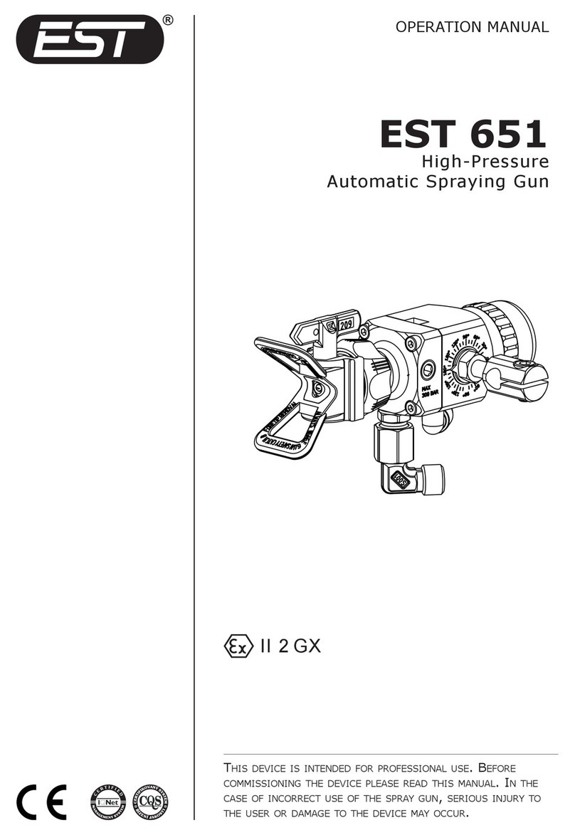
EST 246 User manual

II 2 GX
OPERATION MANUAL
EST 246
air spray gun
These spray guns have been engineered for professional
use. read and undersTand This operaTion manual before
operaTing, doing any service or mainTenance procedure.
incorrecT use may resulT in serious personal injury or
damage To The spray gun.

E01-039 GB rev: 02 2011/11
®
EST + a.s.
Podolí 1237
584 01 Ledečnad Sázavou
CZECH REPUBLIC
VAT code: CZ 25 25 37 35
EC-DECLARATION OF CONFORMITY
PRODUCT
NAME: Low pressure manual spray gun
TYPE: EST 116, EST 216, EST 246 and their
modifications
VARIANTS: —
USAGE: Liquid paint coating
COMPLIES WITH
European directives
2006/42/EC; 94/9/EC; 2003/10/EC; 2002/44/EC
STANDARDS USED
EN ISO 5349-1; EN ISO 12100; EN 13463-1; EN ISO 13732;
EN 1953+A1; EN 1127-1; EN ISO 3746
ATEX
94/9/EC
Clan:
II Category: 2 Mark: II 2G X
Notified body:
Tech. File:
NB 1026 – FTZÚ, Ostrava, CZ
A243-10
DECLARATION
We are declaring and taking the responsibility that the
properties and parameters of the equipment meet the
safety requirements and the technical requirements, and
that the equipment is safe and meets all the above stated
requirements.
Manufacturer has a certification for quality system management
according to: ČSN EN ISO 9001:2009.
APPROVED BY
Jaromír Vojíř, Technical Manager
In Ledečnad Sázavou
Date: 1 of November 2011

3
EST 246
TABLE OF CONTENTS
SAFETY REGULATIONS 5
Vibrations and noise 5
Work with sprayer 5
Protection during work 6
USE AND DESCRIPTION OF EQUIPMENT 6
Sprayer EST 246 6
Air way - materials used 7
Method of coating substance - material used 7
Advanteges of the new sprayer 7
TECHNICAL PARAMETERS 8
COMMISSIONING 9
Use the hose for the supply of the compressed air: 9
Options for selecting the supply of painting substances 9
Direct connection of fast couplings for the air on the sprayer 9
SPRAYER ADJUSTMENT 9
Adjustment of lead time 9
SERVICING 10
Regulation of the volume of coating substance 10
Regulation of the form of the spraying 10
Regulation of the air supply into the sprayer 11
Repracement of the nozzle system 11
Replacement of the needle seal 11
Replacement of tightening the air valve 11
MAINTENANCE AND CLEANING 13
Principles for maintenance and cleaning 13
Important principles for high-ouality function 13
Versions of felxible supply 14
Other optional accessories 14
SAFETY OF OPERATION 14
TESTING OF PRODUCTS 15
PACKING OF PRODUCTS 15
DISPOSAL 15
WARRANTY TERMS 15
No warranty is provided 15
COMBINATION OF NOZZLE SETS 16

4
EST 246
DEFECTS AND REMOVAL 17
PARTS SPECIFICATION 18
Display of parts 19
Accessories supplied with the equipment 20
Needle sealing set - paint(ident. no. 906 765) 21
Needle sealing set - enamel (ident. no. 906 766) 21
Air valve set - identication number 906 552 22

5
EST 246
SAFETY REGULATIONS
For spraying and manipulation with ammable liquids, the
respective standards are valid. Premises and rooms in which work
with coating substances is performed must be marked and modied
with respect to the class of inammability pursuant to valid standards
and regulations.
If sprayers are used and operated in other countries, local
standards and regulations are valid.
Due to the ow of air and liquids, under certain circumstances
an electrostatic change (electricity) may occur. This may result in
sparks or ames.
To prevent this, it is necessary, particularly for coating substances
with an inammation point under 21°C (nitra, acetone painting
substances, etc. ) and some coating substances of the 2nd class of
inammability heated for higher temperature, to use hoses with
guaranteed electrostatic leakage – it is required to ensure certied
hoses with this indication.
Vibrations and noise
The value of vibrations transferred to the hands does not exceed
the maximum permitted value according to Government Directive
No. 272/2011 Coll.
The level of noise depends on the size of the jet system and the
value of the input pressure which varies within the range 80 – 90dB(A).
The permitted level of noise is according to the Collection of Laws
No. 272/2011 is 85dB(A) and, therefore it is necessary to use
protective work aids for the protection of ears.
Work With sprayer
The sprayer works with a pressure of 6 bars. Never direct the
sprayer towards yourself, other persons or animals. Solvents and
diluents may cause chemical burns. During assembly or disassembly
of the jet or during cleaning or interruption of work, be very careful
and ensure that the sprayer is always secured against any activation.
This will prevent any consequent injury. Before the execution of any
repair work, the sprayer must be disconnected from the compressed
air.
ATTENTION
Do not use the basic construction of sprayers fro solvents from the group of
chlorinated hydrocarbons, e.g. 1.1.1. trichlorethane and methyl chloride may
call chemical reaction with aluminium and also with galvanic or galvanized
parts and to create detonating mixture which may lead to the explosion.
ATTENTION
All workers performing service and maintenance of the device must be
familiarized in a proven manner with safety regulations and with the Service
and Maintenance Manual.

6
EST 246
protection during Work
When spraying and manipulating application materials and when
cleaning the equipment, follow the instructions of the producers of
these materials. To protect the skin and eyes, use protective work
aids (clothes, gloves, respirators, protective masks, breathing
devices, protective glasses, protective creams, etc.).
USE AND DESCRIPTION OF EQUIPMENT
Air sprayer EST 246 is a sprayer with a lower pressure supply of
material. The sprayer has a complete stainless route for the applied
material.
The system for spraying with decreased pressure of the spraying
air to the mouth of the nozzle of the sprayer, similar to PR system,
is designed for the application of a wide range of applied materials
by air spraying in the industry, car varnishing workshops, plastic
industry, wood processing, ceramic industry, particularly for the
application of base paints, enamels and glazing where an increased
output of the sprayer is necessary.
This sprayer is characterized by excellent holding and balancing
in the hand, as well as easy and less tiring manipulation. Assembly
threads 6, 7 and 23 are sealed by a suitable sealing binder (LOCTITE
542).
Using the sprayer, it is possible to apply all types of coating
substances which are designated for the application of spraying and
their chemical composition does not intervene into the parts of the
sprayer. The recommended distance from the mouth of the jet from
the sprayed area (spraying distance) depends on the size of the jet
set and the type of coating substance, which is 150-190 mm.
The semi-automatic seal on the needle ensures the
maximum time of maintenance-free and reliable activity
of the seal. Mechanical tightening of the seal enables the
prolongation of the time between vertical repairs. The system
connects the advantages of the automatic and mechanical
solution for tightening the seal on the needle.
sprayer est 246
Using this type of the sprayer, it is possible to process the following
coating substances can be processed:
solvent-borne – synthetic, nitro, acetone, urethane, epoxy and
acrylic, base, llers and upper varnishes
water-borne – acrylic, silicate, silicone and urethane substances
and other application materials with similar properties.
Working environment IE 72 according to ČSN – EN 60721-3-7.

7
EST 246
air Way - materials used
Body of the sprayer alloy Al with surface treatment Ni
Sealing elements POM, PE, PTFE
Parts stainless, brass
method of coating substance - material used
Body of the sprayer tiled with stainless material AISI 304
Sealing elements PTFE (for NH); graphite (for abrasive ma-
terials)
Parts stainless AISI 304
adVanteges of the neW sprayer
»progressive design and ergonomic body form ensuring excellent
holding
»extremely light sprayer with the standard weight of only 468 grams
»high transfer efciency exceeding the legislative requirements in
terms of the environment
»new system for spraying with a decreased spraying output pressure
on the mouth of the nozzle, high ne spraying and quality of the
allocation in the beam
»new series of modernised nozzle systems
»new ergonomic control elements of regulation and the overall new
construction
»standard delivered jet sets characterized by perfect tightness
»special surface treatment of the body of the sprayer ensures
perfect cleaning
»the system for sealing the sprayer from highly resistant materials
ensures resistance when washing in washing machines
»new sealing elements from PTFE
»semi-automatic sealing which prolongs the service life
»high resistance to solvents
»high level of inspection of each product

8
EST 246
TECHNICAL PARAMETERS
Maximum permitted input overpressure of air............ 6 bars
Working pressure of air – recommended* .......... 2,5-3,5 bar
Maximum pressure of applied material .......................6 bar
Consumption of air .................................300-420 Nl.min-1
Range of the output of sprayed coating substance* .............
.............................................................. 400-680 g.min-1
Spraying distance * .......................................150-190 mm
Quality of air:
– max. dew point ....................................................+3°C
– max. content of oil........................................... 1 mg/m3
– max. size of solid particles .....................................5 μm
– max. temperature...............................................+40°C
Weight of the gun (standard) ...................................468 g
Connecting dimensions
– air supply ..........................................................G 1/4“
– supply of coating substance ........................... M 14 x 1,5
Classication of environments
* depends on the size of the jet set and the type of coating
substance
II 2 GX

9
EST 246
COMMISSIONING
Before commissioning it is necessary to clean the sprayer from
preservation substances using a suitable degreasing agent – ush
the sprayer with solvent for coating substances which will be applied.
Each sprayer is adjusted and tested in the production plant
(quality test).
use the hose for the supply of the compressed air:
»within 10 metres with the clearance of 8 mm
»over 10 metres with the nominal clearance of 9.5 mm
options for selecting the supply of painting substances
The construction of the EST 246 A sprayer has the option to select
the supply:
»lower xed supply – stainless tube with connecting threading
M 14 x 1.5
»exible lower supply – calibrated hose, e.g. Pa, Pu 8/6 and 6/4
»lower supply, standard version - threading M 14 x 1,5
direct connection of fast couplings for the air on the
sprayer
The construction of the sprayer enables to connect air fast
couplings to the sprayer. The fast coupling drift from RECTUS, type
26 SFIW 13, can be attached onto the supply threading.
The producer recommends using branded fast couplings with low
pressure loss and long service life.
For the air supply, it is possible to use a fast coupling only
during the application of water-borne coating substances
which do not require electrostatic leakage.
SPRAYER ADJUSTMENT
While complying with the basic requirements for maintenance, the
sprayer does not need any adjustment. Each sprayer is adjusted and
tested in the production plant. During dismantling and assembling
due to replacing the jet set or worn parts, it is necessary to check
the adjustment of the following parts:

10
EST 246
adjustment of lead time
»activation of air before opening the outow of the
coating substance
Reproduction of the quality of EST parts ensures that
during standard replacement of the jet system, the lead is
permanently set, it is not necessary to be adjusted.
»seal on the needle is semi-automatically tightened with the
option of manual tightening.
SERVICING
Suitable maintenance is an important precondition for high-
quality functioning. The construction of the sprayer is designed so
that these requirements are easily kept.
The jet systems are produced from stainless AISI 304 and are
delivered as spare parts in the set nozzle with needle. To achieve
high quality spraying, it is necessary to ensure the cleanliness of the
jet system, prevent damage to the neck of the nozzle, cleanliness
and integrity of the highly precise holes in the air hose. During
replacement or cleaning of the nozzle, it is necessary to tighten the
nozzle so it tightens well. The recommended tightening moment on
the nozzle is 10 Nm.
The sprayer is adjusted and tested in the production plant - quality
test.
regulation of the Volume of coating substance
This regulation restricts the lift of the
needle which causes throttling of the ow of
the substance in the nozzle. Turning the stop
bolt (20) changes the lift of the needle and the
volume of the applied material. We recommend
using this method only temporarily. A more
suitable method is to select the jet set or to
decrease the pressure of the sprayed air (in
the case that this will not decrease the quality of the spraying). In the
case of full tightening of the stop bolt, this will
prevent the lift of the needle and unwanted
spraying during manipulation.
regulation of the form of the spraying
Air ows through the holes in the wings
of the air hose which spreads the form of the
beam. The volume is regulated by turning the

11
EST 246
regulation wheel. By turning to the left, the supplied volume of air
is increased and the beam is spread.
regulation of the air supply into the sprayer
This regulation (17) is located in the upper
axis of the sprayer and enables throttling of the
supplied volume of air into the sprayer by which
the operator may decrease the volume of air for
spraying without the necessity to change on the
air regulator in the distribution system.
repracement of the nozzle system
After dismantling the stop bolt (20) remove the spring for the
needle (18) with the bearing (19) and the needle (2). For easier
manipulation, press the lever which pushes out the needle from
the rear part of the sprayer. Remove the nozzle (1) from the front
part by unscrewing. Dismantle the nozzle from the sprayer by the
attached wrench (41). Before assembly of a new nozzle system,
it is recommended to clean the assembly areas. Attach the new
nozzle and fully tighten. The recommended tightening moment on
the nozzle is 10 Nm. On the rear part, insert the needle with the
spring and attach the stop bolt with the nozzle.
replacement of the needle seal
In the case of leaks, it is necessary to
tighten the seal (29) using the bolt on the
seal (32) turn the bolt in a clockwise direction
into the position where the seal tightens
again. In the case that it is not possible to
turn the bolt on the seal and the seal does
not tighten, it is necessary to replace the seal
with new. Unscrew the bolt on the seal (32)
and remove the set of the old seal. Before
the insertion of a new seal, clean the area
for the seal. Insert a new seal (29), guiding
of the spring (30) and spring of the seal (31) from the set of the
needle sealing. Tighten the bolt of the seal so that the seal reliably
tightens. The seal on the enamel is replaced similarly.
replacement of tightening the air ValVe
»demontáž: (g a) Dismantle the stop bolt (20) with the spring
(18) and the needle (2). Using the wrench (41) dismantle the
air regulation (17) with the spring (16) from the sprayer. Insert
by pressing the level of the cone (15) into the sprayer, insert
the assembly drift (36) from the air valve set, insert the needle
and push out sealing U1 (13) from the sprayer by pressing the
lever. The sealing will remain on the code which you consequently
29 30 31 32

12
EST 246
remove from the sprayer. (g b) Using the assembly drift press
sealing U1 (13) from the dismantled air regulation. Insert into the
regulation the drift (36) and by screwing the stop bolt (20) push
out the sealing (13) from the regulation.
g. a) g. b)
»assembly: Insert new sealing U1 (13) from the valve set into
the assembly wrench (42) and insert it into the body of the
sprayer. Similarly insert sealing U1 into the dismantled air
regulation.
»Insert the new cone (15) from the set into the body, screw the
spring with air regulation into the body, insert the needle and
screw the stop bolt with the spring.
We recommend ordering repairs from an authorized service,
see the service manual.
13 36 20
151336
42
13

13
EST 246
MAINTENANCE AND CLEANING
principles for maintenance and cleaning
»Do not leave dried substances in the sprayer or on the surface.
Removing is difcult (if it is dried) and there can be damage to the
smooth area.
»Clean holes in the jet system with great care because this is the
most important part representing the quality of the spraying.
»If necessary, lubricate after cleaning the lever case (27), the
functional part of the regulation bolt (21) and the threads on the
regulation bolts with suitable grease (MOLYKOTE Cu 7439).
»The sprayer is washed in the respective solvent corresponding
to the type of sprayed coating substance. It is possible to clean
the sprayer in a washing machine for sprayers. Never dip into
the solvent or do not leave the sprayer for a long time in an
environment with solvent vapours.
important principles for high-ouality function
»Correctly selected jet set according to the type of the coating
substance and the size of the item (for special requirements
we recommend to contact the technical sales service at the
manufacturer).
»Correctly treated air for spraying (without dirt, water and oil –
perfectly ltered).
»Filtered painting substances with the correct viscosity and without
dirt (comply with and follow the instructions of the manufacturers
of the painting substances).
»Well prepared (cleaned and maintained) painting sprayer.
»Keep to the recommended pressures of air for spraying.
ATTENTION
Do not use metal pieces for cleaning!!!
Connect
pressured air
Blow through
12

14
EST 246
Versions of felxible supply
type order no. note
hose set 8/6 (Fig. 1) 906 876 the hose is not included in the
delivery
hose set 6/4 (Fig. 2) 906 883 the hose is not included in the
delivery
Fig. 1 Fig. 2
other optional accessories
»Pressure regulator with the separator
»Separator of dirt from the air
»Fast couplings of hoses
»Hoses
»Compressor
»Protective means for the painter
SAFETY OF OPERATION
The product fulls regulations and standards related to products
of this type.
All employees authorized to perform service and
maintenance must be familiarized in a proven manner with
safety and health regulations for work in paint shops, with
the user and maintenance manual for the sprayer.
The operator must train the operators and equip employees with
the stated personal protective aids. The training or provision of
information can be requested from the supplier of the equipment.
RELATED STANDARDS
ČSN EN ISO 12100, ČSN EN ISO 13732-1, ČSN EN 894, ČSN EN ISO 4414,
ČSN EN 1037+A1, ČSN EN 1070, ČSN EN 1127-1, ČSN EN 13463-1,
ČSN EN 60079-0, ČSN EN 60721-3-7/A1, ČSN EN ISO 11204, ČSN 33 2030

15
EST 246
TESTING OF PRODUCTS
»Functional and pressure tests are performed for each product in
the manufacturing plant.
PACKING OF PRODUCTS
»According to individual parts for delivery.
DISPOSAL
»After termination of the service life of the parts or the sprayer,
after cleaning the sprayer can be put into sorted waste.
»Packaging materials for the product (Catalogue number 200101,
see Regulation of the Ministry of the Environment No. 381/2001
Coll.) are liquidated as mixed communal waste. Put the used paper
package into a separate waste collection.
WARRANTY TERMS
»See Service Manual
noWarranty is proVided
»In the case of mechanical damage or incorrect handling of the
product.
»In the case of damage, wearing or failure caused by incorrect
or inadequate maintenance, abrasion, corrosion or the use of
unstable parts or materials.
»In the case of unpermitted and unprofessional intervention into
the device.
»The warranty is not applicable for parts of a consumer nature, for
example, sealing elements, springs, jet with needle, stop valve
and the jet for which wearing depends on the abrasive properties
of the applied substance, pressure and other circumstances.

16
EST 246
COMBINATION OF NOZZLE SETS
air nozzle nozzle set
type identification number type identification number
UL 906 590
10U 906 567
12U 906 568
14U 906 570
PC 906 646
10U 906 567
12U 906 568
14U 906 570
16U 906 571
18U 906 572
22U 906 574
PS 906 603
14U 906 570
16U 906 571
18U 906 572
22U 906 574
14UT 906 842
18UT 906 844
22UT 906 846
EL 907 213 28U 906 852
GL 907 200 40U 906 853
The nozzle set consists of a nozzle with a ring and needle.
Nozzle set with „T“ - with prolonged nozzle service life - the
enamels.

17
EST 246
DEFECTS AND REMOVAL
defects raeson remoVing
The sprayer does
not spray or spray is
interrupted
air floWs from nozzle
»empty pressure vessel on the
painting substance
»doplnit nátěrovou hmotu
»untightened nozzle on the
body of the sprayer
»correctly tighten nozzle
»damaged seal in the body of
the nozzle
»replace the seal
»blocked hole in the nozzle »clean
»closed regulation of the
volume of the coating
substance
»set regulation
air does not floW from the nozzle
»closed air supply closed
»regulation of air supply
»open the supply
»open air regulation on the
sprayer
Resulting spraying is
bent or club-shaped
»dirt in semi-rings on the
nozzle and jet
»clean the dirt, do not
damage semi-rings
»damaged hole in the nozzle or
neck of the jet
»replace with new
»dirt in wings or auxiliary holes »clean, do not damage holes
»loosely tightened nozzle »correctly tighten the nozzle
Resulting spraying
has less paint in the
centre
»too high volume of air in wings »set the correct volume of
the regulation of the width
of spraying
»high pressure of air for
spraying
»decrease air pressure
»low viscosity of the painting
substance
»modify the viscosity
according to regulation of
the producer
The resulting
spraying is less at
»less air in the wings »set the higher volume by
the regulation of the width
of spraying
»low pressure of air for
spraying
»increase the pressure
»high viscosity »correctly modify and
measure with viscosity
meter

18
EST 246
PARTS SPECIFICATION
position name identification number Quantity
1 Air cap Specication
according to the table
“Combination of nozzle
sets“
1
2 Nozzle set 1
3 Body EST 246 Not delivered —
4“O“ ring 33,3 x 1,6 105 081 1
5 Lever 806 510 1
6 Air threads 806 687 1
7 Holder 806 884 1
8 Pin 3 x 8 119 027 1
9 Bolt M 4 x 8 114 137 1
10 Fixed supply 906 868 1
11 Flexible supply see page 14 1
13 Sealing U1 135 016 2
14 Piston seat 135 017 1
15 Cone 906 561 1
16 Cone spring 124 082 1
17 Air regulation 906 454 1
18 Needle spring 124 066 1
19 Spring bearing 806 553 1
20 Stop bolt 806 457 1
21 Regulating bolt 806 694 1
22 Sealing 804 424 1
23 Regulation case 804 426 1
24 Regulation wheel 806 464 1
25 Set of rings 906 439 1
26 Bolt 114 247 1
27 Lever case 804 530 1
28 Lever bolt 802 011 1
29 Seal 70° 806 674 1
30 Spring guiding 806 675 1
31 Seal spring 804 290 1
32 Sealing bolt 806 466 1
•33 Washer of the seal 804 866 2
•34 Seal 800 470 1
•35 Sealing bolt ST 806 693 1
• sealing set for enamel and materials of a similar character

19
EST 246
display of parts
26
25
24
23
22
21 2
18
19
20
1
5
29 30 31 32
34
33
33 35
27
28
6
8
9
7
2
4
3
13
14
15
16
13
17
10
11

20
EST 246
accessories supplied With the eQuipment
posotion name identification number Quantity
40 Hex key, size 7 152 019 1
41 Universal wrench 806 697 1
42 Assembly wrench 906 699 1
43 Brush for cleaning 139 100 1
44 Sprayer hook 904 599 1
25 Set of rings 906 439 1
46 Insert 128 670 1
25 46 42 40 43 41 44
Table of contents
Other EST Paint Sprayer manuals
Popular Paint Sprayer manuals by other brands

Kobalt
Kobalt SGY-AIR160TZ operating instructions

Graco
Graco Contractor II instructions

Graco
Graco 255963 Instructions-parts list

Campbell Hausfeld
Campbell Hausfeld DH5700 operating instructions

Graco
Graco field lazer s100 Operation manual

Central Pneumatic
Central Pneumatic 60314 Owner's manual & safety instructions