EST iO64 User manual

Page 1 of 10 DATA SHEET 85005-0131
Not to be used for installation purposes. Issue 7
EST Catalog u Small Building Fire Alarm Solutions
06-27-13
Overview
The Edwards EST iO64 intelligent life safety system offers the
power of high-end intelligent processing in a configuration that
delivers an uncomplicated solution for small to mid-sized applica-
tions. With intelligent detection, electronic addressing, automatic
device mapping, optional Ethernet® connectivity, and a full line of
easily-configured option cards and modules, this flexible system
offers advanced features that benefit building owners and contrac-
tors alike.
The iO64 provides one Class B analog device loop that supports
up to 64 device addresses, and two Class B Notification Appli-
ance Circuits (NACs). Optional Class A device wiring is available
with the use of a module.
This life safety system features an attractive design that fits with
any decor. Its distinctive doorfront offers a contemporary look
that’s available with red or silver finishes. All LED indicators and its
large backlit display remain easy to see at all times.
The iO64 supports a wide range of accessories and related equip-
ment, including:
• Signature Series intelligent modules, detectors, and bases
• R-Series remote annunciators
• option cards that expand system capacity and extend system
capabilities
• fully integrated CO detection using Signature Series 2 detec-
tors with or w/o audible signaling.
Features
• Comes standard with one loop that supports up to 64
intelligent devices of any type and two Class B NACs.
• Supports Signature Series modules and detectors
• Combines the Signature intelligent releasing module with
Signature multisensor detectors for reliable suppression
• Form C for Alarm and Trouble, Form A for Supervisory
• Electronic addressing with automatic device mapping
• Optional Ethernet port for diagnostics, programming and
variety of system reports
• Two programmable switches with LEDs and custom labeling
• Supports Genesis horn silence over two wires and UL
1971-compliant strobe synchronization
• Supports up to eight serial annunciators, (LCD, LED-only, and
graphic interface).
• Can use existing wiring for most retrofit applications
• Upload/download remotely or locally
• Two-level maintenance alert reporting
• Pre-alarm and alarm verification by point
• Adjustable detector sensitivity
• 4 x 20 character backlit LCD display
• Optional earthquake hardening: seismic Importance Factor 1.5
iO64 Intelligent
Life Safety System
7165-1657:
0244
S3000
COA 6020

Page 2 of 10 DATA SHEET 85005-0131
Not to be used for installation purposes. Issue 7
Operation
The front panel provides an
easy-to-use operator’s inter-
face, as well as all the neces-
sary controls for front panel
programming. A large back-lit
80-character LCD displays
system status, event details,
and programming prompts.
Large tactile control buttons
are easy to see in low light
conditions, and bright multi-
color LEDs offer at-a-glance
status indication.
Control buttons
Button Description
System Reset Initiates a system reset.
ACK/Panel
Silence
Silences the panel and remote annunciators during
an active trouble, supervisory, or alarm event and
acknowledges new event activations.
Signal Silence Alarm mode: Silences active notification appliances.
Pressing Signal Silence a second time turns NACs back
on.
Drill Initiates a drill confirmation. Pressing drill a second time
turns off the drill function.
Remote
Disconnect
Dialer: Disables or enables dialer.
Dialer set to modem only: Disables or enables the
common alarm relay.
Left arrow Display mode: Moves the cursor to the left.
Menu mode: Toggles between programming
selections.
Right arrow Display mode: Moves the cursor to the right.
Menu mode: Retrieves a programming option’s sub
menu and toggles between a programming option’s
selections.
Up arrow Display mode: Advances to the previous event.
Menu mode: Moves the cursor up.
Down arrow Display mode: Advances to the next event.
Menu mode: Moves the cursor down.
Enter Display mode: Displays selected event details.
Menu mode: Retrieves a programming option’s sub
menu or jumps to the Save function in the menu.
Entry mode: Enters the selected data into the system.
Cancel Display mode: Exits the detailed information display.
Menu mode: Exits the current menu level.
Entry mode: Clears the current entry.
Menu Display mode: Enters the menu mode
Menu mode: Exits menu mode
Space Enters a space, such as a space between words.
Alphanumeric
keypad
Entry mode: Pressing a button once enters the number
on the button. Pressing the button twice enters the
secondary value.
Programmable
buttons
These buttons can be programmed to control outputs,
disable devices or unlatch system outputs.
Application
The iO64 life safety system is a powerful intelligent solution for small
to mid-sized buildings. Advanced analog technology delivers the
benefits of flexible system installation, while a clean and easy-to-
operatate user interface makes panel operation and system mainte-
nance quick and intuitive.
The smart choice
Signature Series electronic addressing eliminates the tedium of
setting dipswitches, and automatic device mapping ensures that
each device resides on the system at its correct location. Mean-
while, innovative programming features allow the system designer
to customize powerful built-in features to precisely suit the needs
of the building owner.
Flexibility built right in
Two fully-programmable front panel switch/LED combinations pro-
vide an added measure of flexibility. Their slide-in labels take the
mystery out of custom applications, and present a clean finished
appearance.
Perfect for retrofits
The iO64 is particularly well-suited to retrofit applications. All
connections are made over standard wiring – no shielded cable
required. This means that in most situations existing wiring can be
used to upgrade a legacy control panel to iO-Series technology
without the expense or disruption of rewiring the entire building.
Signals with a difference
iO64 NACs are configurable to fully support the advanced signal-
ing technology of Edwards Genesis and Enhanced Integrity notifi-
cation appliances. These devices offer precision synchronization of
strobes to UL 1971 standards. For Genesis devices, enabling this
feature allows connected horns to be silenced while strobes on
the same two-wire circuit continue to flash until the panel is reset.
Clear-cut remote annunciation
Remote annunciation is a strong suit of the iO64. Up to eight an-
nunciators can be installed on a single system. Compatible annun-
ciators include a range of LED and LCD models that provide zone
or point annunciation, as well as common control capabilities.
The iO64 also supports graphic annunciation with optional graphic
annunicator interface modules. Each interface provides common
control, indicators, and LED drivers. Consult the Ordering Informa-
tion section for details.
A complete line of accessories
The iO64 life safety system is supported by a complete line of
intelligent detectors, modules and related equipment. Consult the
Ordering Information section for details.

Page 3 of 10 DATA SHEET 85005-0131
Not to be used for installation purposes. Issue 7
Panel Operation Options
Language English or French
Marketplace U.S. or Canada
AC fail delay Off: Off-premise notification of an AC power failure
is immediate.
1 to 15 hours: Delays the off-premise notification of
an AC power failure by the time period selected.
Zone resound On: NACs resound each time a device in the zone
goes into alarm even if they were silenced
Off: Inhibits the NACs from turning on again (after
they were silenced) when a second device in the
zone goes into alarm.
Reset inhibit after
NACs turn on
Off: Panel reset is operational immediately.
1 minute: Panel reset is inhibited for one minute.
Auto signal
silence
Off: Allows immediate silencing of signals from an
off-normal condition using the Signal Silence button
5 to 30 minutes: Delays the silencing of signals
from an off-normal condition by disabling the Signal
Silence button for the time period selected.
Day start Start time for daytime sensitivity
Night start Start time for nighttime sensitivity
Date U.S.: MM/DD/YYYY, Canada: DD/MM/YYYY
Sounder Base Six configuration settings
Mapping Disabled: Device mapping is not available
Enabled: Device mapping is available
LCD banner Banner text for line one and line two. Each line is
capable of up to 20 characters.
Event notification Zone: When a device is a member of a zone, only
the zone information is sent to the LCD display,
LEDs, printer, and dialer.
Zone/device: Zone information is sent to the LCD
display and LEDs. Device information is sent to the
printer and dialer.
Device: Only device information is reported.
System LEDs
LED Description
Alarm Red LED. Flashes when there is an active alarm
event on any loop. On steady once acknowledged.
Trouble Yellow LED. Flashes when there’s a fault with a
monitored circuit or system component or when a
circuit is disabled. On steady once acknowledged.
Sup Yellow LED. Flashes when there is an active super-
visory event on any loop. On steady once acknowl-
edged.
Ac Power Green LED. On when the panel has AC power.
Disable Yellow LED. Double-flashes when there is a dis-
abled circuit, alarm relay, or remote annunciator.
Ground
Fault
Yellow LED. On steady during an active ground
fault.
Test Yellow LED. Flashes when performing an audible
walk test. Steady indicates a silent test.
Monitor Yellow LED. Flashes when there is an active monitor
event on any loop. On steady once acknowledged.
Service
Detector
Yellow LED. Indicates that detector needs servicing.
Signal
Silence
Yellow LED. On steady indicates that NAC circuits
are turned off but the panel is still in alarm.
Remote
Discon-
nect
Yellow LED. On steady indicates that the dialer is
disabled or that the alarm relay is enabled or dis-
abled when the dialer is set to modem only.
Drill Yellow LED. Indicates that the panel is in drill.
Reset Yellow LED. Indicates that the panel is resetting.
Panel
Silence
Yellow LED. Indicates that the panel has been
silenced during an active trouble, supervisory, or
alarm event and indicates that new event activa-
tions have been acknowledged.
User Keys Yellow LED. Indicates the programmed key function is active.
Dimensions
D1
D2 D3
D4
D5
D6
Surface mounting holes
Semi-flush mounting holes
Surface mounting holes
Panel dimensions, in (cm)
Model D1* D2 D3 D4 D5* D6
iO64 21.50
(54.6)
3.85
(9.8)
7.5
(19.0)
15.5
(39.4)
14.25
(36.2)
10.25
(26.0)
* Add 1-1/2 in. (3.81 cm) to D1 and D5 dimensions for trim kit.
Programming
iO-Series life safety systems are simple to set up, yet also offer ad-
vanced programming features that put these small building panels
into a class of their own. The auto programming feature quickly
gets the panel operational using factory default settings. Basic
zone and point settings can be programmed easily through the
front panel interface, so the system is up and running in no time.
For more advanced system configuration and correlation groups
programming, iO-Series systems interface to a PC running com-
patible iO-CU software. This option offers full system configuration
in the familiar Windows® operating environment. Connection is
typically made to a laptop through the panel’s optional RS-232
communications port, which can also be used to connect a sys-
tem printer.
Among the many advanced features of iO-Series control panels
is the optional network card. This module provides a standard
10/100 Base T Ethernet® network connection that permits access
to the control panel from any remote location with the correct
communications protocols. The connection can be used to
download to the panel from the iO-CU, or upload and view system
reports using the iO-CU.
Available system reports include:
• Correlation groups • Device details
• Device maintenance • History
• Internal status • System configuration
• System status • Walk test
• Dialer • CO runtime

Page 4 of 10 DATA SHEET 85005-0131
Not to be used for installation purposes. Issue 7
Wiring & Configuration
Notification appliance circuits (TB2)
The iO64 comes equipped with two notification appliance circuits.
Each circuit can be individually configured for continuous, tempo-
ral, synchronized, latching, and coded output.
Circuit Specifications
Circuit Type 2 Class B, Class A optional when Class A card is
installed.
Each circuit is 2.5 amps.
Voltage 24 VFWR
Current 3.75A total (115/230 60hz)
3.0A total (230v 50hz)
2.5 A max per circuit
Impedance 26 Ω total, 0.35 µF max
EOLR 15 K Ω, ½ W
+
NAC1 -
NAC2+
NAC2 -
NAC1+
EOLR
TB2
+
+ +
Class B wiring
Class B wiring
TB2
TB6
EOLR
NAC3 -
NAC4+
NAC4 -
NAC3+
EOLR
NAC1 -
NAC2+
NAC2 -
NAC1+
+ +
+ +
+ +
+ +
Class A wiring
TB2
TB6
NAC1 -
NAC2+
NAC2 -
NAC1+
+ +
+ +
+
+
- -
- -
- -
- -
- -
- -
- -
- -
-
-
Signature Device loop
The system provides one device loop circuit that can be used
with any mix of Signature Series detectors and modules. The loop
circuit is supervised for opens, shorts, and grounds.
The Signature Loop Controller uses broadcast polling and ad-
vanced communications formats to regularly check the entire
device circuit for anomalies. If a change of state is detected at the
circuit level, the Loop Controller then uses a direct address search
to find the reporting device. This two-staged technique ensures
that only new information is transmitted, thus allowing for a re-
duced baud rate while still achieving nearly instant device reporting.
Circuit Specifications
Device loops 1 loop Class B, Class A optional when Class A card
is installed. Supporting up to 64 device addresses.
Communication
line voltage
Maximum 20 V peak-to-peak
Circuit current 0.5 A max
Circuit
impedance
66Ω total, 0.7 µF, max
Isolators 64 maximum
Loop 1 SEC
Loop card
+
Loop 1 PRI
+
++
Loop
device
Loop
device
Data Line
Class B wiring
Class A wiring
Loop 1 SEC +
Loop 1 PRI
+
++
Loop
device
Loop
device
Loop card Data Line
-
-
- -
-
-
- -
Loop 1 SEC
Loop card
+
Loop 1 PRI
+
++
Loop
device
Loop
device
Data Line
Class B wiring
Class A wiring
Loop 1 SEC +
Loop 1 PRI
+
++
Loop
device
Loop
device
Loop card Data Line
-
-
- -
-
-
- -
Class B Wiring Class A Wiring
Marking indicates output signal polarity when the circuit is active.
Polarity reverses when the circuit is not active. Wire notification
appliances accordingly. Notification appliance polarity shown in
active state.
Annunciator loop (TB4)
The control panel provides a connection for up to eight serially
driven and supervised remote annunciators.
Circuit specifications
Device loops Class B (Style Y) or Class A (Style Z)
Circuit voltage 2.55 V
Circuit current 30 mA max
Circuit
impedance
Up to 8 annunciators or 4000 feet
+
–
TB4
+
–
Channel 1 Channel 2
CH1 (+) IN
CH1 ( ) IN
–
CH2 (+) IN
CH2 ( ) IN
–
Annunciator
+
–
TB4
+
–
C
hannel 1
C
hannel 2
CH1 (+) IN
CH1 ( ) IN
–
CH2 (+) IN
CH2 ( ) IN
–
Annunciator
Terminal wiring location
+
–
TB4
+
–
Channel 1 Channel 2
CH1 (+) IN
CH1 ( ) IN
–
CH2 (+) IN
CH2 ( ) IN
–
Annunciator
+
–
TB4
+
–
C
hannel 1
C
hannel 2
CH1 (+) IN
CH1 ( ) IN
–
CH2 (+) IN
CH2 ( ) IN
–
Annunciator
Terminal wiring location
Class B Class A
Alarm, trouble, and supervisory relay (TB3)
The trouble relay is normally-open, held closed, and opens on any
trouble event or when the panel is de-energized. The supervisory
relay is normally-open, and closes on any supervisory event. The
alarm relay changes over on any alarm event.
Relay specifications
Alarm Trouble Supervisory
Type Form C Form A
Voltage 24 VDC at 1 A resistive 24 VDC at 1 A resistive
Relay circuits can only be connected to power-limited sources.
Auxiliary & Smoke power outputs (TB3)
The control panel provides two auxiliary power outputs which can
be used for powering ancillary equipment such as remote an-
nunciators and two wire smoke detectors. Aux 2 can be software
selected to operate continuous. The circuit is supervised for shorts
and grounds.
Note: For a complete list of devices that can be connected to this
circuit, refer to the iO Series compatibility list (p/n 3101064).
Circuit specifications
Circuit voltage range 21.9 to 28.3 V
Resettable circuit
(Aux power 2)
24 VDC nominal at 500 mA
Continuous circuit
(Aux power 1)
24 VDC nominal at 500 mA. Use this circuit for
powering two-wire smoke detectors.
Note: Any current above 0.5 amp connected to both Aux 1 and 2 will reduce the total
available NAC power by that amount.

Page 5 of 10 DATA SHEET 85005-0131
Not to be used for installation purposes. Issue 7
SA-232 RS-232 interface
The SA-232 card provides an RS-232
interface with iO-Series panels. It can be
used for connecting a printer to the control
panel to print system events. The card also
can be used for connecting a computer to
download a configuration program from
the iO-CU to the control panel.
The RS-232 card is installed on the plastic assembly and con-
nects to the main circuit board via a ribbon cable.
SA-232 specifications
Operating voltage Standard EIA-232
Terminal rating 12 to18 AWG (0.75 to 2.5 sq mm)
Operating environment
Temperature
Humidity
32 to 120°F (0 to 49°C)
0 to 93% RH, noncondensing at 90°F (32°C)
SA-ETH Ethernet Interface Card
Network cable
Ethernet card
To network
connection
SA-ETH wiring
The SA-ETH card provides a
standard 10/100 Base T Ethernet
network connection for connect-
ing to an intranet, a local net-
work, or the Internet. The card
can be used to download
configuration programming from
the iO-CU to the panel over the
network.
The Ethernet card is installed on
the plastic assembly and con-
nects to the main circuit board
via a ribbon cable.
SA-ETH specifications
Ethernet 10/100 Base T
Operating environment
Temperature
Humidity
32 to 120°F (0 to 49°C)
0 to 93% RH, noncondensing at 90°F
(32°C)
Option Cards
iO-Series panels are supported by a complete line of modules and
related equipment that enhance performance and extend system
capabilities. Option cards are easy to install and set up. They
simply plug directly into the control panel main circuit board or are
connected to it with a ribbon cable. After installation, terminals
remain easily accessible for quick connection of field wiring. The
cabinet provides ample room for wire routing, keeping wiring neat
and easy to service at all times.
GND (black wire)
TXD (white wire)
RXD (red wire)
SA-232 wiring
SA-CLA Class A Module
The SA-CLA card
provides Class A
capability for NAC,
loop, and an-
nunciator wiring.
Its terminal block
provides the wiring
connection for NAC
return wiring. The
card is required for
loop and annuncia-
tor Class A wiring
even though this wiring does not return to the SA-CLA card. The
SA-CLA is compatible with iO64 control panels only. iO500 panels
are Class A ready. The SA-CLA is installed directly to the control
panel circuit board using its plastic standoffs and plug connection.
SA-CLA specifications
Operating voltage 24 VFWR
Operating current 2.5 A/circuit, 3.75A total (115/230 60hz)
3.0A total (230v 50hz)
Circuit impedance 26 Ω, 0.35 µF, max
Terminal rating 12 to18 AWG (0.75 to 2.5 sq mm)
Operating environment
Temperature
Humidity
32 to 120°F (0 to 49°C)
0 to 93% RH, noncondensing at 90°F
(32°C)
SA-CLA wiring
Class A card installed
on main circuit board
NAC1
NAC2+
NAC2
NAC1+
+ +
+ +
+
+
TB2 on main
circuit board
1
1
1
2
2
2
3
3
3
4
4
4
5
5
5
6
6
6
7
7
7
8
8
8
11
11
12
12
16
16
15
15
14
14 13
13 9
9
10
10
3 2 1
3 2 1
+
_
24 VDC
auxilliary
power
(not resettable)
++
+
+
+
+
+
Power in
Power out
SMK
JP1
JP1
Data in
Data out
Terminate
or to next
UM
Two-wire smoke
detectors
Two-wire smoke
detectors
SMK Smoke Power Converter
The SMK Smoke Power
Converter Module provides a
regulated power source for two-
wire smoke circuits connected
to a Signature data circuit. The
SMK monitors the operating
power from the power supply.
When power begins to degrade,
the SMK provides the necessary
operating voltage to the two-
wire smoke detection circuits.
SMK specifications
Input voltage 21.9 to 28.3 VDC (not resettable)
Output voltage 24 VDC nom. at 200 mA, max., special
applications
Ground fault
impedance
10 k ohm
Operating environment
Temperature
Humidity
32 to 120°F (0 to 49°C)
0 to 93% RH, noncondensing at 90°F (32°C)
Storage temperature –4 to 140°F (–20 to 60°C)
Compatible electrical
boxes
North American 4 inch square x 2-1/2 in.
(64 mm) deep 2 gang box or Standard 4 in.
square box 1-1/2 in. (38 mm) deep
Wire size 14, 16, or 18 AWG wire (1.5, 1.0, or 0.75 sq.
mm) (Sizes 16 and 18 AWG are preferred)

Page 6 of 10 DATA SHEET 85005-0131
Not to be used for installation purposes. Issue 7
SA-DACT Dialer
The SA-DACT provides communications between the control
panel and the central station over a telephone line system. It
transmits system status changes (events) to a compatible digital
alarm communicator receiver over the public switched telephone
network. The dialer is capable of single, dual, or split reporting
of events to two different account and telephone numbers. The
modem feature of the SA-DACT can also be used for uploading
and downloading panel configuration, history, and current status
to a PC running the iO-CU.
Phone line 1
Phone line 2
To wall
phone jack
Phone cables
(supplied) RJ31 jacks
SA-DACT
wiring
The dialer phone lines connect
to connectors on the dialer’s
main circuit board. Phone line 1
connects to connector J4 and
phone line 2 connects to
connector J1.
The SA-DACT queues messages and transmits them based on
priority (alarm, supervisory, trouble, and monitor). Activations are
transmitted before restorations.
The SA-DACT is installed on the plastic assembly and connects to
the main circuit board via a ribbon cable.
SA-DACT specifications
Phone line type One or two loop-start lines on a public,
switched network
Phone line connector RJ-31/38X (C31/38X)
Communication formats Contact ID (SIA DC-05)
Operating environment
Temperature
Humidity
32 to 120°F (0 to 49°C)
0 to 93% RH, noncondensing at 90°F
(32°C)
Compatible DACRs
Receiver Models Formats
Ademco 685 Contact ID
FBII CP220 Contact ID
Osborne-Hoffman OH 2000 Contact ID
Radionics D6600 Contact ID
Silent Knight 9800 Contact ID
Sur-Gard SG-MLR1, MLR2 Contact ID
SIGA-REL Releasing Module
The SIGA-REL is an analog addressable module that communi-
cates directly with the fire alarm panel Signature loop controller. The
SIGA-REL controls sprinkler, pre-action and deluge systems, and
may also be used to release extinguishing agents such as CO2,
Halon, or foam. The module is easily configured in the field and of-
fers a wide range of options that ensure dependable service, while
preventing the unnecessary release of extinguishing agent.
SIGA-REL specifications
Power riser
Input voltage
Supervisory current
Riser input current
Alarm
24 Vdc (power limited)
25 mA, max.
4 amps maximum
170 mA min.; 4 A max.
Release
circuits
Output rating
Valves per circuit
Max. supervisory current
Nominal supervisory current
Supervisory voltage
End of line device
2 A @ 24 Vdc (per circuit)
4 valves, max.
0.4 mA (short circuit)
0.18 mA
26 Vdc, max. (open circuit)
47k Ohm EOL
Pre-release
alarm circuits
Output rating
Max. supervisory current
Nominal supervisory current
Supervisory voltage
End of line device
2 A @ 24 Vdc (for each
circuit)
0.4 mA (short circuit)
0.18 mA
26 Vdc, max. (open circuit)
47k Ohm resistor
Manual
release input
circuit
Max. supervisory current
Nominal supervisory current
Supervisory voltage
End of line device
Circuit type
Circuit capacitance
0.4 mA (short circuit)
0.18 mA
26 Vdc, max. (open circuit)
47k Ohm resistor
Class B N.O. latching
0.1 µF, max
Abort circuit
Max. supervisory current
Nominal supervisory current
Supervisory voltage
End of line device
Circuit type
Circuit capacitance
0.4 mA (short circuit)
0.18 mA
26 Vdc, max. (open circuit)
47k Ohm resistor
Class B N.O. non- latching
0.1 µF, max
First alarm
output relay Contact rating 3 A @ 24 Vdc
(0.6 power factor) Form C
Signature
Data line
Operating voltage
Supervisory current
Alarm current
5.2 to 19.95 Vdc
1000 µA
1000 µA
Note: Output circuits are power-limited when the riser circuit is power-limited.
For detailed specification and ordering information on the SIGA-REL, refer
to Data Sheet 85001-0531 -- Releasing Module.
Loop Controller
MR
A
M
Release Circuit2
RELA-EOL Release Circuit1
SD
RELA-EOL
SD
M
SD
A
MR
Signature Series smoke detectors
Signature Series modules
Horn circuit
Strobe circuit
Service Disconnect Station
Manual Abort Station
Manual Release Station
First Alarm Output Relay
Auxiliary
Power Supply
M
Fire Alarm Control Panel
iO64 Control Panel
Releasing Module
(SIGA-REL)

Page 7 of 10 DATA SHEET 85005-0131
Not to be used for installation purposes. Issue 7
Specifications
Device loops 1 loop Class B, Class A optional, supporting
up to 64 device addresses
Notification appliance
circuits
2 Class B, Class A optional, 2.5 amps each
Power supply 3.75 A FWR total at 120/230 VAC 60 Hz
3.0 A FWR total at 230 VAC 50 Hz
0.5 amps aux power
NAC Operating voltage 24 VDC. NAC minimum voltage: 19.5 VDC @
20.4 V battery voltage
Loop operating voltage 20 V peak-to-peak
Primary power 120 VAC, 60 Hz, 230 VAC 50-60 Hz
Aux Power 1
(Continuous circuit)
24 VDC nominal at 500 mA. A SMK module is
required when using the SIGA-UM module to
support two-wire smoke detectors.
Aux Power 2
(Resettable circuit)
24 VDC nominal at 500 mA.
Auxiliary output 19 to 25.7 VDC
Base panel current draw Standby: 155 mA Alarm: 204 mA
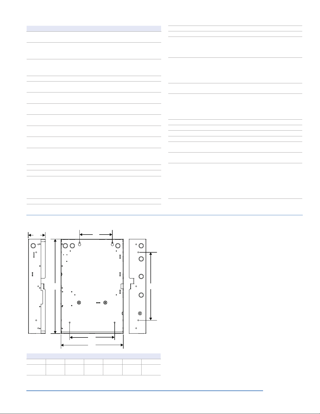
Battery placement iO64 cabinets accommodate up to 10 A/H
batteries. Use an external cabinet for larger
battery sizes.
Batteries Batteries must be sealed lead acid type only.
Maximum charging capacity = 26 Ah.
Loop circuit Maximum loop resistance: 66 Ω. Maximum
loop capacitance: 0.7 µF. Style 4, 6, and 7
wiring. 64 isolators maximum
Loop circuit max detector
standby current
1.5 mA (see the UL and ULC compatibility list
for your panel for the maximum quantity of
detectors per circuit)
Compatibility ID 100
Alarm contact Form C 24 VDC @ 1 A (resistive load)
Trouble contact Form C 24 VDC @ 1 A (resistive load)
Supervisory contact Form A 24 VDC @ 1 A (resistive load)
Environmental Temperature: 0 to 49°C (32 to 120°F).
Humidity: 0 to 93% RH, noncondensing
Terminal rating All terminals rated for 12 to 18 AWG (0.75 to
2.5 sq mm)
Serial communications Voltage: 2.55 V. Current: 30 mA max
Remote annunciator 8 drops max, RS-485 Class B, Class A
Input zones 16 max.
Agency Listing UL864, UL2017, CSFM, ULC and NYFD
COE#6020
Ordering Information
Part Description
iO64 Intelligent Single Loop Analog Systems
iO64G 1 Loop System, 64 point capacity, 2 Class B NACs, gray
door, surface mount enclosure, 115 Vac, English.
iO64GD 1 Loop System, 64 point capacity, 2 Class B NACs, 2
Line Dialer, gray door, surface mount enclosure, 115 Vac,
English.
iO64R 1 Loop System, 64 point capacity, 2 Class B NACs, Red
Door, surface mount enclosure, 115 Vac, English.
iO64RD 1 Loop System, 64 point capacity, 2 Class B NACs, 2
Line Dialer, Red Door, surface mount enclosure, 115 Vac,
English.
iO64G-2
(Note 2)
1 Loop System, 64 point capacity, 2 Class B NACs, gray
door, surface mount enclosure, 230 Vac, English.
iO64R-2
(Note 2)
1 Loop System, 64 point capacity, 2 Class B NACs, Red
door, surface mount enclosure, 230 Vacr, English.
iO64G-SP
(Note 2)
1 Loop System, 64 point capacity, 2 NACs, gray door.
surface mount enclosure, 115 Vac, Spanish.
iO64G-2-SP
(Note 2)
1 Loop System, 64 point capacity, 2 NACs, gray door.
surface mount enclosure, 230 Vac, Spanish.
iO64G-PG
(Note 2)
1 Loop System, 64 point capacity, 2 NACs, gray door.
surface mount enclosure, 115 Vac, Portuguese.
iO64G-2-PG
(Note 2)
1 Loop System, 64 point capacity, 2 NACs, gray door.
surface mount enclosure, 230 Vac, Portuguese.
iO64GL
(Note 1)
1 Loop System, 64 point capacity, 2 Class B NACs, 16-
zone LED display, gray door, surface mount enclosure,
115 Vac, English.
iO64GL-F
(Note 1)
1 Loop System, 64 point capacity, 2 Class B NACs, 16-
zone LED display, gray door, surface mount enclosure,
115 Vac, French.
SA-TRIM1 Flush mount trim, black
Replacement Electronics
64elec-iO Replacement electronics kit, complete motherboard and
user interface, English
64elec-iO-SP
(Note 2)
Replacement electronics kit, complete motherboard and
user interface, Spanish
64elec-iO-PG
(Note 2)
Replacement electronics kit, complete motherboard and
user interface, Portuguese
64elec-iO-FR
(Note 1)
Replacement electronics kit, complete motherboard and
user interface, French
Option Cards
SA-DACT Dual Line Dialer/Modem, supports 4/2 and Contact ID,
mounts in cabinet on base plate.
SA-232 Serial Port (RS-232), for connection to printers &
computers, mounts in cabinet to base plate
SA-ETH Ethernet Port, Slave, mounts in cabinet on base plate.
SA-CLA Class A adapter module. Provides Class A capacity on
NACs. Mounts in cabinet on main board.
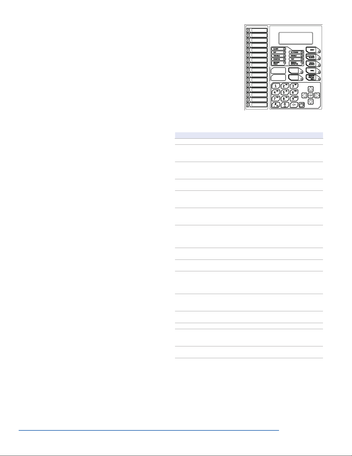
D16L-iO-1 LED Annunciator module, 16 X 2-LED zones (4 max
programmable for sup). Mounts in cabinet to left of LCD
display for zones 1-16.
D8RY-iO-1
(Note 1)
LED Annunciator module, 16 X 2-LED zones (4 alarm
only, 8 supervisory only, 4 alarm or supervisory). Mounts
in cabinet to left of LCD display for zones 1-16.
Remote Annunciators (refer to Data Sheet 85005-0128)
LCD Remote Annunciators (mount to standard 4” square box)
RLCD Remote Annunciator, 4X20 LCD & Common Indicators
for displaying system status. White housing.
RLCD-R Remote Annunciator, 4X20 LCD & Common Indicators
for displaying system status. Red housing.
RLCD-C Remote Annunciator, 4X20 LCD. Common controls and
status indicators. White housing.
RLCD-CR Remote Annunciator, 4X20 LCD. Common controls and
status indicators. Red housing.
RLCDF
(Note 1)
Remote Annunciator, 4X20 LCD & Common Indicators
for displaying system status. White housing, French
RLCD-CF
(Note 1)
Remote Annunciator, 4X20 LCD. Common controls and
status indicators. White housing, French
RLCD-SP
(Note 2)
Remote Annunciator, 4X20 LCD. Common system status
indicators. White housing. Spanish.
RLCD-PG
(Note 2)
Remote Annunciator, 4X20 LCD. Common system status
indicators. White housing. Portuguese.
RLCD-C-SP
(Note 2)
Remote Annunciator, 4X20 LCD. Common controls and
status indicators. White housing. Spanish.
RLCD-C-PG
( Note 2)
Remote Annunciator, 4X20 LCD. Common controls and
status indicators. White housing. Portuguese.
GCI Graphic Annunciator Driver Master for R-Series
annunciators. Outputs for 32 LEDs, connection to
common control switches and LEDs.
GCIX Graphic Annunciator Driver Expander for use with GCI
Masters. Outputs for 48 LEDs, 24 switch inputs.

Page 8 of 10 DATA SHEET 85005-0131
Not to be used for installation purposes. Issue 7
Model Description Ship wt.
Intelligent Detectors & Bases
SIGA2-PHCOS Intelligent Multisensor Photoelectric/Heat
Detector with carbon monoxide sensor
0.4 (0.16)
SIGA2-PHS Intelligent Multisensor Photoelectric/Heat
Detector
SIGA2-PHSB Intelligent 4D Multisensor Detector (Black) -
UL/ULC Listed
SIGA2-PCOS Intelligent Photoelectric Detector with carbon
monoxide sensor
SIGA2-PS Intelligent Photoelectric Detector
SIGA2-HRS Intelligent combination fixed temperature/
rate-of-rise heat detector
SIGA2-HFS Intelligent fixed temperature heat detector
SIGA2-HCOS Intelligent fixed temperature heat detector
with CO sensor
SIGA2-COS Intelligent Carbon Monoxide Detector
SIGA-HFS Intelligent Fixed Temperature Heat Detector -
UL/ULC Listed
0.5 (0.23)
SIGA-HRS Intelligent Fixed Temperature/Rate-of-Rise
Heat Detector - UL/ULC Listed
SIGA-IPHS Intelligent 4D Multisensor Detector - UL/ULC
Listed
SIGA-IPHSB Intelligent 4D Multisensor Detector (Black) -
UL/ULC Listed
SIGA-PHS Intelligent 3D Multisensor Detector - UL/ULC
Listed
SIGA-PS Intelligent Photoelectric Detector - UL/ULC
Listed
SIGA-SD Intelligent SuperDuct Detector 2.4 (1.1)
SIGA-SB Detector Mounting Base
0.2 (0.09)
SIGA-SB4 4-inch Detector Mounting Base c/w SIGA-TS
Trim Skirt
SIGA-RB Detector Mounting Base w/Relay
SIGA-RB4 4-inch Detector Mounting Base /w Relay c/w
SIGA-TS Trim Skirt
SIGA-IB Detector Mounting Base w/Fault Isolator
SIGA-IB4 4-inch Detector Mounting Base w/ Fault
Isolator c/w SIGA-TS Trim Skirt
SIGA-LED Remote Alarm LED
Model Description Ship wt.
SIGA-AB4G Audible (Sounder) Base 0.3 (0.15)
SIGA-TS4 Trim Skirt (supplied with 4-inch bases) 0.1 (.04)
SIGA-AB4GT Audible (Sounder) Base for CO and Fire
Detectors 0.3 (0.15)
SIGA-TCDR Temporal Pattern Generator 0.3 (0.15)
Modules
SIGA-CC1 Single Input Signal Module (Standard Mount) 0.5 (0.23)
SIGA-MCC1 Single Input Signal Module (UIO Mount) 0.18 (0.08)
SIGA-CC1S Synchronization Output Module (Standard
Mount) 0.5 (0.23)
SIGA-MCC1S Synchronization Output Module (UIO Mount) 0.18 (0.08)
SIGA-CC2 Dual Input Signal Module (Standard Mount) 0.5 (0.23)
SIGA-MCC2 Dual Input Signal Module (UIO Mount) 0.18 (0.08)
SIGA-CR Control Relay Module (Standard Mount) 0.4 (0.15)
SIGA-MCR Control Relay Module (UIO Mount) 0.18 (0.08)
SIGA-CRR Polarity Reversal Relay Module (Standard
Mount) 0.4 (0.15)
SIGA-MCRR Polarity Reversal Relay Module (UIO Mount) 0.18 (0.08)
SIGA-RM1 Riser Monitor Module (Standard Mount) 0.5 (0.23)
SIGA-MRM1 Riser Monitor Module (Plug-in) 0.18 (0.08)
SIGA-IO Input/Output Module (Standard Mount) 0.34 (0.15)
SIGA-MIO Input/Output Module (Plug-in) 0.22 (0.10)
SIGA-MAB Universal Class A/B Module (Plug-in) 0.18 (0.08)
SIGA-CT1 Single Input Module 0.4 (0.15)
SIGA-CT2 Dual Input Module 0.4 (0.15)
SIGA-MCT2 Dual Input Plug-in (UIO) Module 0.1 (0.05)
SIGA-IM Fault Isolator Module .5 (.23)
SIGA-MM1 Monitor Module 0.4 (.15)
SIGA-WTM Waterflow/Tamper Module 0.4 (.15)
SMK Smoke Power Converter Module 0.4 (0.15)
SIGA-REL Analog addressable releasing module 0.52 (0.23)
276A-REL
Manual releasing station (single-action).
English markings, black text on yellow
polycarbonate body.
1.0 (0.45)
Analog Addressable Devices & Accessories
LED Remote Annunciators & Expander (mount to standard 4”
square electrical box)
RLED-C Remote Annunciator. Common controls and status
indicators with 16 X 2-LED groups for zone display. White
housing.
RLED-CR Remote Annunciator. Common controls and status
indicators with 16 X 2-LED groups for zone display. Red
housing.
RLED-CF
(Note 1)
Remote Annunciator. Common controls and status
indicators with 16 X 2-LED groups for zone display. White
housing, French.
RLED-C-SP
(Note 2)
Remote Annunciator, common controls and status
indicators. 16 groups w/2 LEDs each for zone display.
White housing. Spanish.
RLED-C-PG
(Note 2)
Remote Annunciator, common controls and status
indicators. 16 groups w/2 LEDs each for zone display. White
housing. Portuguese.
RLED24 Remote Annunciator Zone expander. 24 X 2-LED groups
with custom label areas for display of alarm and trouble.
White housing.
RLED24R Remote Annunciator Zone expander. 24 X 2-LED groups
with custom label areas for display of alarm and trouble.
Red housing.
Remote Annunciator Cabinets & Accessories
RA-ENC1 Remote Annunciator Enclosure, key locked with
plexiglass window for one RLCD(C) or RLED(C).
RA-ENC2 Remote Annunciator Enclosure, key locked with
plexiglass window with space for 2 of either RLCDx,
RLEDx or RLED24.
RA-ENC3 Remote Annunciator Enclosure, key locked with
plexiglass window with space for 3 of either RLCDx,
RLEDx or RLED24.
RKEY Keyswitch, single gang, provides key operated enable or
disable of common controls on RLCD or RLED units.
LSRA-SB Surface Mount Box - for R Series single units.
Programming Tools
iO-CU EST Series configuration and diagnostics utility.
260097 RS232 cable, 4 conductor, DB9 PC interface
Note 1— Available in Canada only. Note 2— Available in International
markets.

Page 9 of 10 DATA SHEET 85005-0131
Not to be used for installation purposes. Issue 7
Note:
For earthquake anchorage, including detailed mounting weights and
center of gravity detail, please refer to Seismic Application Guide 3101676-
EN. Approval of panel anchorage to site structure may require local AHJ,
structural, or civil engineer review.
Standby batteries must be mounted externally from fire panel in separately
mounted BC-1 enclosure. Order BC-1 aand BC-1EQ separately.
Model Description Ship wt.
278A-REL
Manual releasing station (double-action).
English markings, black text on yellow
polycarbonate body.
1.0 (0.45)
RELA-ABT Manual Abort Station. English markings,
black text on yellow polycarbonate body. 1.0 (0.45)
RELA-SRV-1
Service Disconnect Switch. One n/c contact
and one n/o contact. English markings, white
text on blue polycarbonate body.
1.0 (0.45)
RELA-EOL Polarized end-of-line relay. English markings
on stainless steel cover. 0.2 (0.1)
SIGA-UIO2R Universal Module Board w/Riser Inputs - Two
Module Positions 0.32 (0.15)
SIGA-UIO6R Universal Module Board w/Riser Inputs - Six
Module Positions 0.62 (0.28)
SIGA-UIO6 Universal Module Board - Six Module
Positions 0.56 (0.25)
Accessories
GCI Graphic Annunciator Driver, provides outputs
for common indicators and 32 alarm/supv
zones as well as inputs for common switches.
Provided with a snap track for mounting in
custom graphic enclosures.
CTM City Tie Module. Provides connection to a
local energy fire alarm box. 0.6 (0.3)
RPM Reverse Polarity Module 3.0 (1.36)
BC-1 Battery Cabinet. 14.0" x 18.25" x 7.25". Holds
2 12V24A batteries. 50.0 (22.7)
BC-1R Battery Cabinet - Red. 14.0" x 18.25" x 7.25".
Holds 2 12V24A batteries. 50.0 (22.7)
MFC-A Multifunction Fire Cabinet, 8" x 14" x 3.5" -
RED. 20.6 (9.4)
PT-1S System Printer - Desktop style. 36.6 (16.6)
BC-1EQ Seismic hardening Kit for iO series panels.
Includes battery hardening for BC-1 enclosure
and components to harden panel internal
components. See note.

Page 10 of 10 DATA SHEET 85005-0131
Not to be used for installation purposes. Issue 7
06-27-13
Contact us...
Email: edwards.fir[email protected]
Web: www.est-fire.com
EST is an EDWARDS brand.
1016 Corporate Park Drive
Mebane, NC 27302
In Canada, contact Chubb Edwards...
Email: [email protected]
Web: www.chubbedwards.com
© 2013 UTC Fire & Security Americas
Corporation, Inc. All rights reserved.
Specifications subject to change
without notice. Edwards is part of UTC
Climate, Controls & Security, a unit of
United Technologies Corporation.
Table of contents
Popular Safety Equipment manuals by other brands

MSA
MSA Latchways SRL instructions

Dynello
Dynello Spaceball RS0402 instruction manual

Guardian
Guardian 10870 instruction manual

AES Corporation
AES Corporation 7740 Installation and operation manual

Klein Tools
Klein Tools PoleMaster FPD-5295 instructions

SKYLOTEC
SKYLOTEC MOBILFIX Assembly and operating instructions