Estarmodels PZL-104 WILGA User manual
PZL-104 WILGA
INSTRUCTIONS
www.estarmodels.com
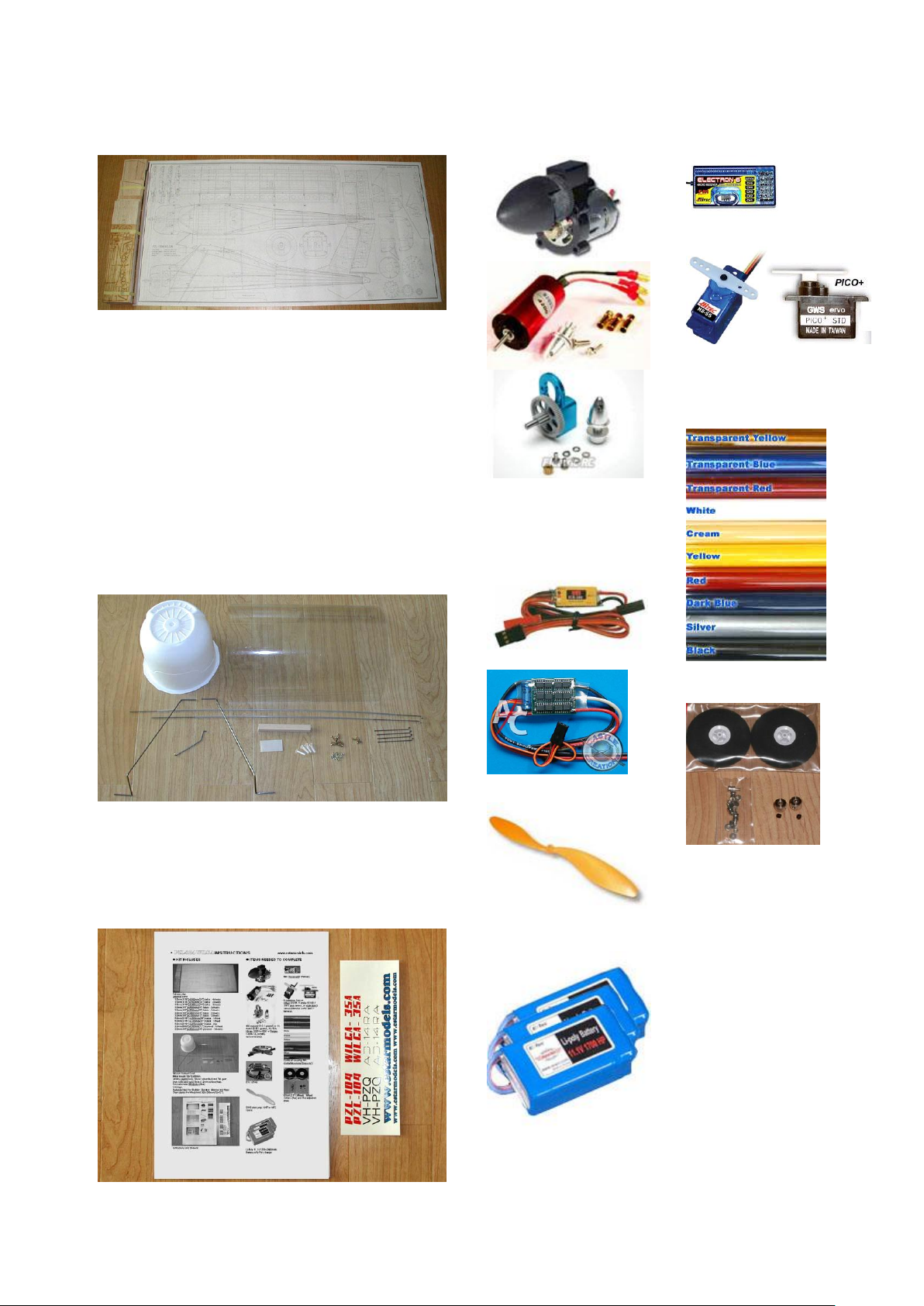
KIT INCLUDES
ITEMS NEEDED TO COMPLETE
Full size plan.
Lasercut parts.
1.5mm(1/16”)xL600mm(24”) balsa : 2sheets
1.5mm(1/16”)xL560mm(22.4”) balsa : 2sheets
1.5mm(1/16”)xL500mm(20”) balsa : 1sheet
1.5mm(1/16”)xL480mm(19.2”) balsa : 1sheet
1.5mm(1/16”)xL450mm(18”) balsa : 1sheet
1.5mm(1/16”)xL430mm(17.2”) balsa : 1sheet
1.5mm(1/16”)xL370mm(14.8”) balsa : 2sheets
1.5mm(1/16”)xL330mm(13.2”) balsa : 2sheets
3.0mm(1/8”)xL600mm(24”) balsa : 2sheets
3.0mm(1/8”)xL500mm(20”) balsa : 2sheets
3.0mm(1/8”)xL430mm(17.2”) balsa : 2sheets
3.0mm(1/8”)xL330mm(13.2”) balsa : 2sheets
5.0mm(3/16”) xL600mm(24”) balsa : 1sheet
5.0mm(3/16”) xL330mm(13.2”) balsa : 1sheet
5.0mm(3/16”) xL553mm(22”) balsa : 2ea
1.8mm(5/64”)xL300mm(12”) plywood : 1sheet
3.0mm(1/8”)xL600mm(24”) plywood : 3sheets
Vacuum formed Cowl.
Motor mount 10x10x90mm.
Landing gears(2ea), Silicon tubes(4ea) and Tail gear.
2mm bolts and nuts(10sets), 2mm screws(4ea).
Wingbolts (4ea).
CA hinge.
Pushrods(4ea) for Rudder, Elevator, Ailerons and flaps.
Clear plastic for Windshield 300x300mm(12x12”).
Instructions and Stickers.
480 motor(2.5~3:1 geared) or BL
motor (5~6:1 geared, 12~15A :
Himax 2025 kv4200 or Feigao
13084-13L kv4462
recommended).
ESC (25A).
GWS slow prop 1047 orAPC
10x5E.
Li-Poly 11.1V 1700~2400mAh
Battery w/Li-Poly charger.
Mini Receiver(6 channel).
6 submicro Servos
(Hitec HS-55 / Futaba S3108 /
GWS pico servos, or equivalant)
Servo extension cords and Y-
harness.
3 rolls of covering film.
(Solite/Monokote/Oracover)
63mm(2.5”) Wheels, Wheel
Collars (4ea) and Rod adjusters
(6ea).
Download full color
instructions from
http://www.estarmodels.com
[Download] menu.
Page 1
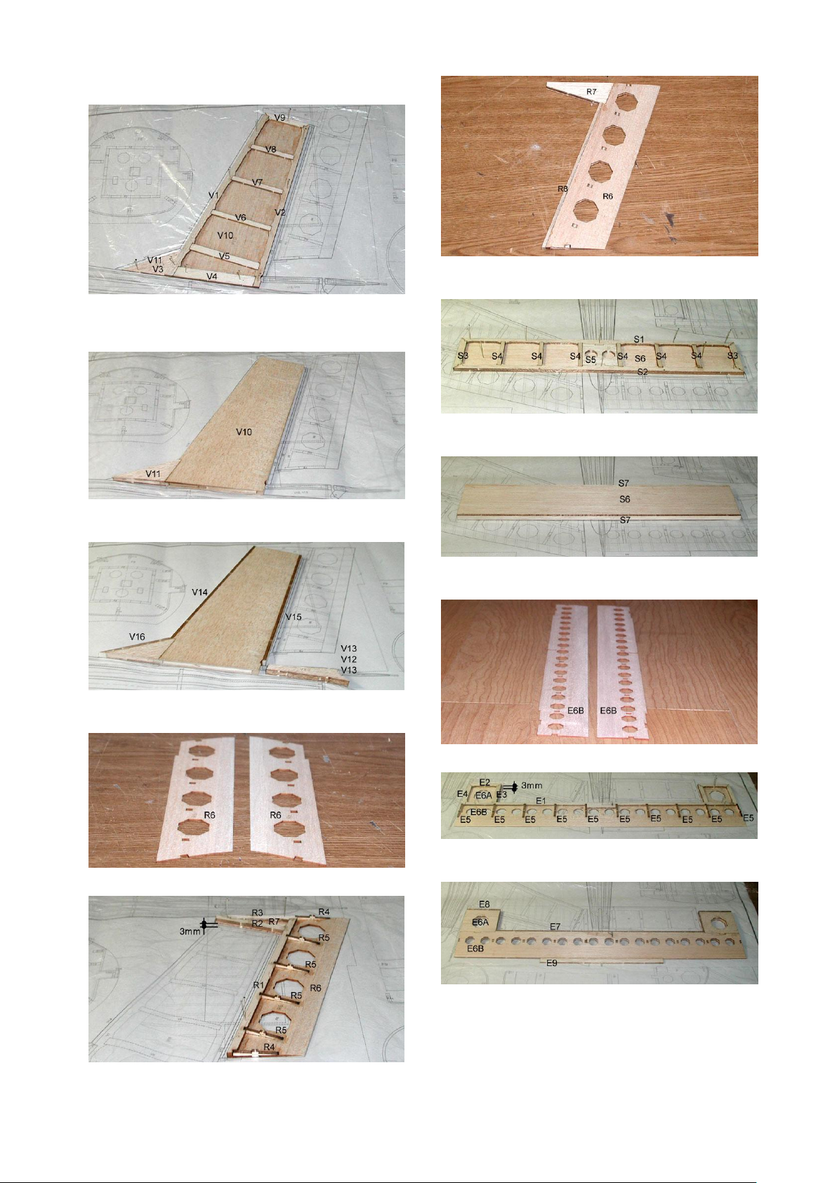
TAIL CONSTRUCTION
6. Glue the sheets(R6,R7) and leading edge(R8) with thick
CA.
7. Pin the stabilizer sheet(S6) and frames(S1-S5).
Glue them with thin CA.
8. Glue the sheet(S6), leading and trailing edges(S7) with
thick CA.
9. Prepare elevator sheets(E6B) and sand trailing edges.
10. Pin the sheets(E6A, E6B) on the plan and glue frames
(E1-E5).
11. Glue the sheets(E6A, E6B), leading edge(E7, E8) and trim
tab(E9) with thick CA.
1. Lay the waxed paper or PVC film over the plan.
Pin the vertical fin sheets(V10-V11) and frames(V1-V9).
Glue them with thin CA.
2. Remove pins and glue the sheets(V10, V11) with thick
CA.
3. Glue the leading and trailing edges(V14-V16) with thick
CA. Glue stabilizer bed(V12, V13) together.
4. Prepare rudder sheets(R6) and sand trailing edges.
5. Pin the sheet(R6) on the plan and glue frames(R1-
R5,R7).
Page 2
12. carefully sand all surfaces.
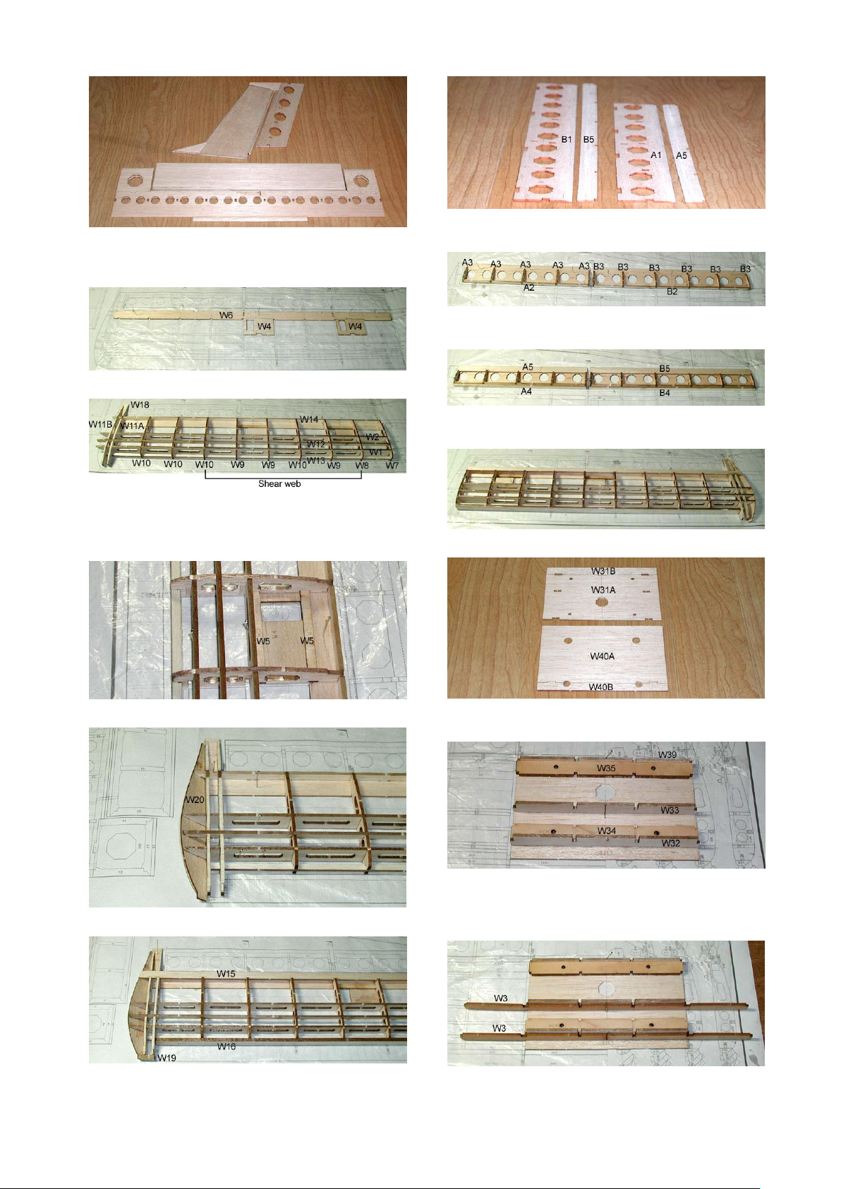
6. Prepare aileron and flap parts(A1, A5, B1, B5) and sand
trailing edges.
7. Assemble sub leading edge(A2, B2) and ribs(A3, B3) and
then, glue them.
8. Glue leading edge(A4, B4) and trailing upper sheet(A5,
B5).
9. Assemble the other side wing.
10. Glue lower sheets(W31A, W31B) together.
Glue upper sheets(W40A, W40B) together.
11. Pin the lower sheet(W31A, W31B) and temporary
assemble spars, trailing edge(W32, W33, W39) and
balsa(below) and plywood(above) wingbolt mounts(W34’s,
W35’s).
12. Temporary install wing joiners(W3).
WING CONSTRUCTION
1. Pin the parts(W4, W6) and glue together with thin CA.
2. Assemble ribs(W7-W11B), main spars(W1, W2), sub
leading edge(W13), sub spar(W12), trailing edge(W14) and
wingtip part(W18) on the plan.And then glue together with
thin CA. Glue Shear webs to the main spars.
3. Glue plywood servo trays(W5) with thin CA.
4. Glue wingtip (W20) with thin CA.
5. Glue leading edge(W16, W19) and trailing upper
sheet(W15).
Page 3
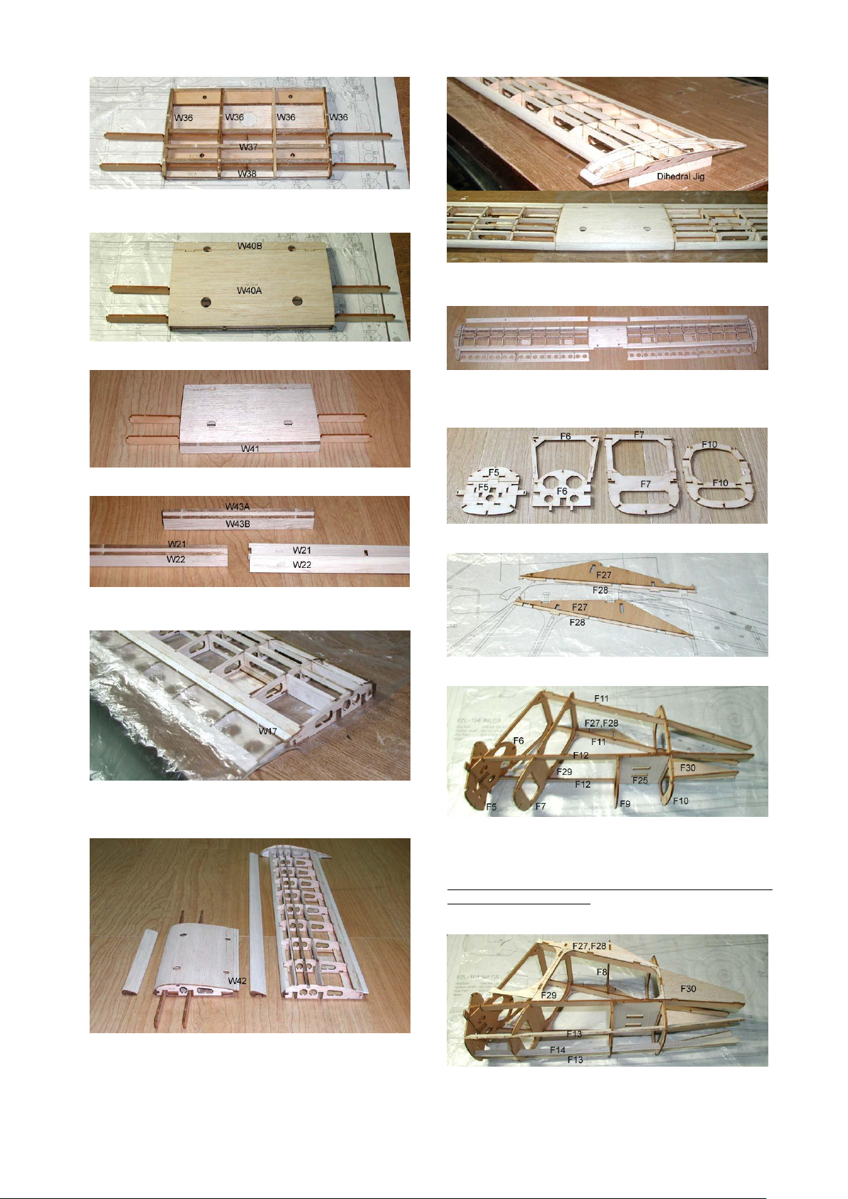
13. Assemble ribs(W36), spar(W37), sub leading edge(W38)
and then, glue them.
14. Glue the upper sheet(W40A, W40B) with thick CA.
15. Sand and glue leading edge (W41) with thick CA.
16. Glue the slat parts together (W21-W22, W43A-W43B)
with thick CA.
17. Glue trailing edge(W17) with thick CA.
Refer to the wing section on the drawing and use cardboard
to make a gap.
18. Glue center trailing edge(W17) with thick CA. Apply
thick CA glue at each joints for reinforcing. And then,
carefully sand surfaces.
19. Glue right and left wings together. Use dihedral jig for
dihedral setting..
20. Wings are ready to cover.
FUSELAGE CONSTRUCTION
1. Glue Bulkheads(F5, F6, F7, F8) together
2. Glue the parts(F27, F28) together
3. Lay right side parts(F27, F28, F29, F30) on the plan and
temporary assemble right longerons(F11, F12), bulkheads(F5,
F6, F7, F9, F10) and servo bed(F25). And then, install left
longerons(F11, F12).
Make sure to pay attention to all bulkheads, the numbers
should be facing forward.
Pins and glues are not required in this step.
4. Install bulkhead(F8), left side parts(F27, F28, F29, F30)
and lower longerons(F13, F14).
Pins and glues are not required in this step.
Page 4
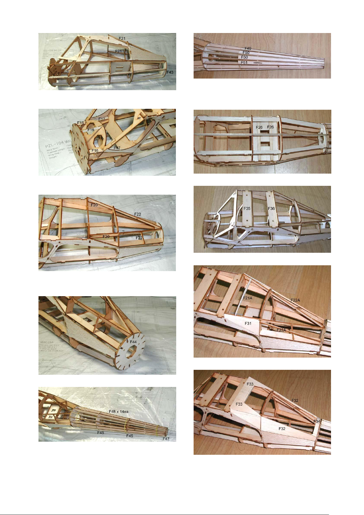
5. Install the part(F21) and bulkhead(F43).
Pins and glues are not required in this step.
6. Install turtle deck frames(F15-F17).
Pins and glues are not required in this step.
7. Install rear cockpit frames(F20, F22).
Now glue all the parts together with thin CA. And then, Apply
thick CA glue at each joints for reinforcing.
8. Glue the bulkhead(F44).
9. Temporary assemble rear fuselage bulkheads(F45, F46,
F47) and longerons(F48).
After sight check down the fuselage to insure against twist,
then apply thin CA.
10. Install panels for pushrod exit(F49-F51).
Apply thick CA glue at each joints for reinforcing.
Insert and glue plastic pipes for elevator and rudder
pushrods.
11. Glue plywood servo rails(F26).
12. Glue plywood wing mounts(F35, F36).
13. Glue rear window frames(F21A, F22A).
14. Glue rear cockpit panels(F32, F33, F34)
Page 5
15. Glue fore cockpit frames(F18, F19), turtle decks(F38)
and fore side panels(F37).
16. Glue landing gear mounts(F23).
17. Glue fuselage side panels(F39, F40).
18. Glue fuselage lower panels(F41, F42).
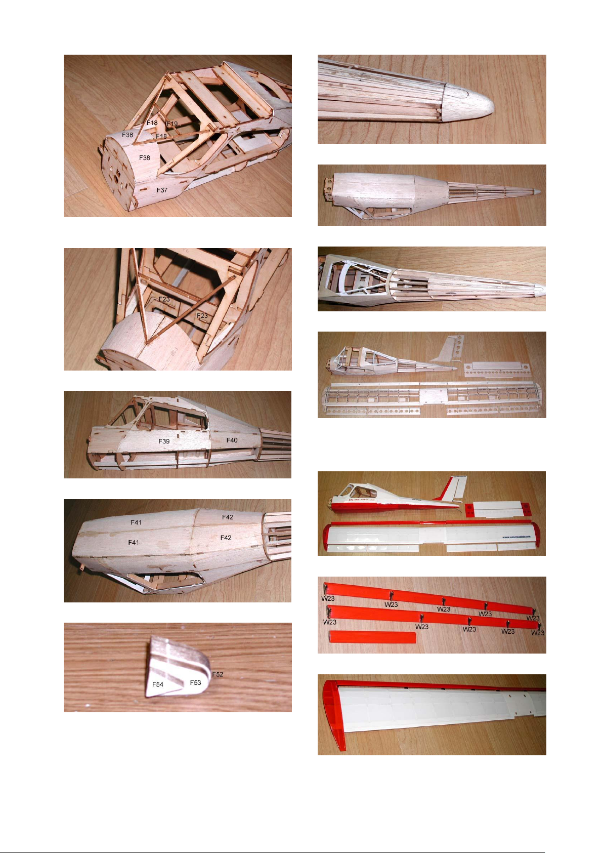
19. Glue tail cone parts together.
20. Temporarily glue and sand tail cone
.
21. Carefully sand fuselage surfaces.
22. Paint cockpit area. Install tail gear and glue tail cone.
23. All the airframes are ready to cover.
COVERING AND EQUIPMENT
INSTALLATION
1. Cover Wilga with your trim choice.
2. Insert and glue plywood slat supports(W23).
3. Glue slats.
Page 6
4. Cut CA hinges as shown above.
5. Make hinge slots and pre-install hinges. (Do not glue
hinges in this step.)
6. Glue stabilizer and vertical fin to the fuselage with thick
CA. (Horizontal tail must be paralleled with wing and
vertical fin must be at right angle to horizontal tail.
Wings must be installed temporarily to align them.)
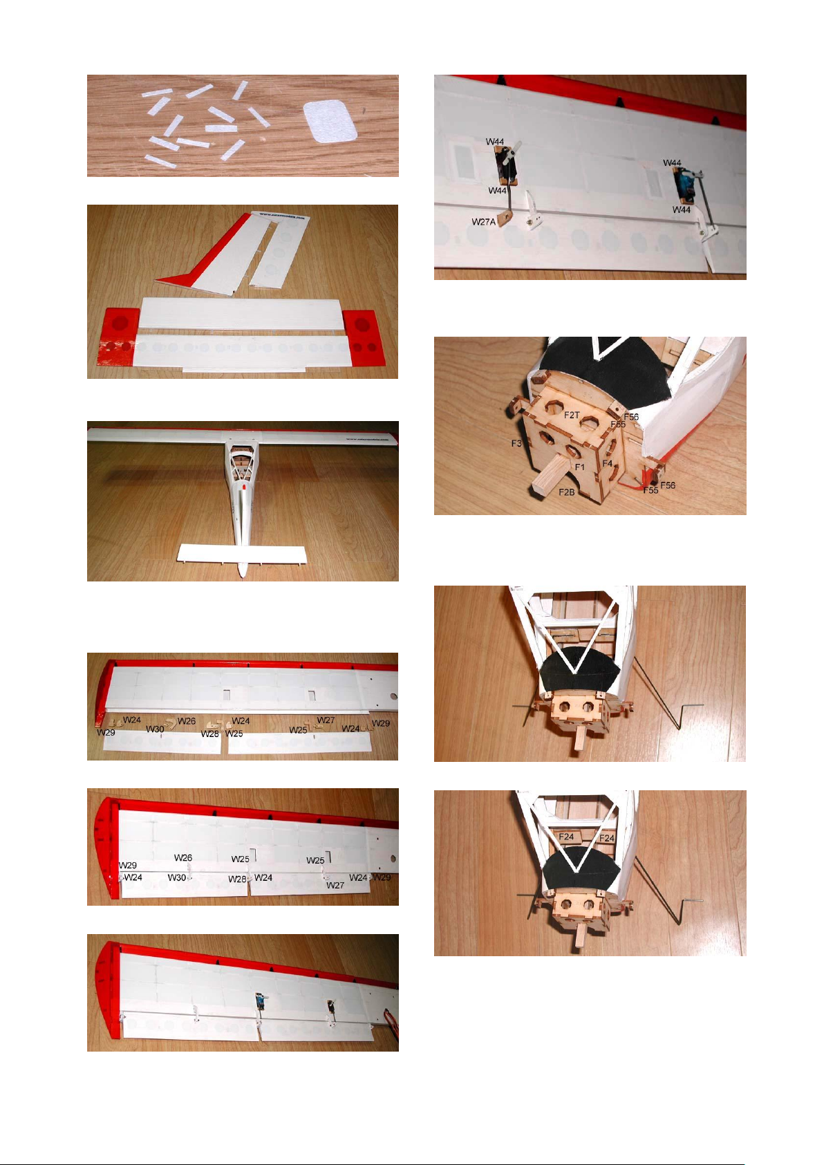
7. Prepare aileron and flap hinges and horns(W24-W30).
8. Insert hinges and horns. Glue them after throwing check.
9. Install aileron and flap servos and connect pushrods.
10. If required, glue optional plywood servo beds(W44).
You may use a servo reverser when you connect flap servos
with Y-harness, if not, install optional flap horn(W27A).
11. Assemble plywood motor mount box(F2-F4) and cowl
mounts(F55, F56).
Make sure to pay attention to bulkhead F1 the numbers
should be facing forward.
12. Insert landing gear.
13. Glue landing gear retainer(F24).
Page 7

14. Assemble dummy landing gear with silicon tubes,
holders(H1) and landing gear struts.
15. Install motor and gearbox.
16. Install and glue elevator and rudder plywood horns.
Apply thin CA to the horns for reinforcing.
17. Insert rudder pushrod to the horn and then glue hinges
with small amount of thin CA.
18. Insert elevator pushrod to the horn and then glue hinges
with small amount of thin CA.
19. Install elevator and rudder servos.
20. Install wheels to the landing gear.
21. Install tail wheel.
22. Glue battery tray(BT).
Page 8

23. Cut clear plastic fore windshield, fold and glue.(refer to
template on the drawing).
24. Cut clear plastic rear windshield and glue.
25. Cut clear plastic right side windshield and glue.
26. Cut clear plastic left side windshield, attach with clear
tape. (This window should be a hatch for battery and your
maintenance.)
27. Tapping with 4mm tap to fit wingbolts.
28. Paint and assemble cowl with 2mm screws and fix
propeller.
29. Assemble wing and fix with wingbolts.
30. Congratulations! Enjoy flying.
Control Throws
The following control throws are recommended starting points.After
you are familiar with this plane, you may increase, or decrease.
- Ailerons : 17mm(2/3”) up, 12mm(1/2”) down.
- Elevator : 25mm(1”) up and down.
- Rudder : 25mm(1”) right and left.
- Flaps : takeoff-20degrees, landing-45degrees
- Flap-Elevator mix : 4mm(5/32”) down for full flap.
Caution
Balancing is very important to fly this model. Balance weight
should be installed in the nose. (Refer to the drawing for the
CG location.)
Page 9

Table of contents
Other Estarmodels Toy manuals


Popular Toy manuals by other brands


FMS
FMS 80mm Dassault Rafale instruction manual

Tiger Electronics
Tiger Electronics Bob's Learning Workshop instructions

Infantino
Infantino The Right Angle owner's manual

Tamiya
Tamiya TRF417X Assembly instruction

Marklin Digital
Marklin Digital 60883 manual

THE WORLD MODELS
THE WORLD MODELS Pilatus PC-6 Porter 40 instruction manual

Simplay3
Simplay3 216060 quick start guide

THUNDER TIGER
THUNDER TIGER TITAN X50 - instruction manual

Steren
Steren CCR-100 quick start guide

Mega Bloks
Mega Bloks Super Tech Heroes Spider-Man 3 manual

FUTABA
FUTABA GY501 instruction manual

Mega
Mega MEGA BLOCKS HALO MAGNETIC SPARTAN Green Spartan Red Team... manual